Home
>
Library - projects, parts, arts, docs, and policy
>
Let's design something! (I've got an idea ...)
>
Topic
Photo-lithography Projector
Posted by Katratszi
|
Photo-lithography Projector August 07, 2014 11:51PM |
Registered: 9 years ago Posts: 3 |
Hey guys, I want to etch some tiny features in to aluminum. And by tiny, I mean somewhere between 1-10 microns.
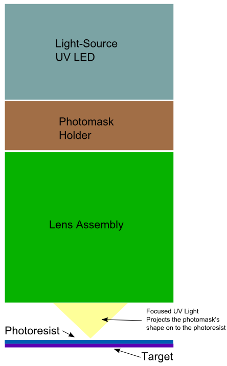
I want to take a stab at an opensource, 3d printable, photo-lithography jig. For those who haven't heard of this process before, it involves projecting a pattern through a photo-mask on to a surface treated with a photoresistive chemical. When thephotoresist is exposed to the light (usually in the UV spectrum, 195nm - 425nm) it hardens. The excess photoresist is then cleaned off the surface leaving a hardened layer. Next the surface is etched, usually with chemicals, to erode the surface of the material. The material with the hardened photoresist, resists this etching process and is left unscathed. The now etched material is removed from the etching bath and cleaned leaving a surface that now bears the pattern left in it by the projected photo-mask.
This process is exceedingly common and even used by some to manufacturer printed circuit boards at home (though not at feature sizes as small as I want). LEDs in the proper light spectrum, and photo-resists are all commonly available online. Etching can be achieved in a variety of ways, in my case I'm going to use electroetching. This type of etching is very simple and involves applying current to a conductive part while it sits submerged in an electrolyte -- basic salt water works just fine. I've done it a couple times with great results.
But there's one small hitch. If you look at the attached basic overview image you'll see what I'm proposing is 4 basic parts. A light source, photo mask holder, lens assembly, and a target platform. The light source will just be one, or many UV LEDs in the proper spectrum (most likely at 400nm). The photo-mask itself is basically just printed clear plastic, so the holder doesn't really need to be much more than a tray. The target platform, is well, just a tray to hold the target material. That leaves the lens-assembly. See, for this to work properly the photo-mask has to be projected and magnified on to the target surface.
And this is the part where I need help. I have absolutely no experience with lenses nor even where to begin on selecting lenses to create the compound lens necessary to project the photo-mask.
What I do know is that even the cheapest home desktop printers can print at 600 DPI. Theoretically that could mean printed features as small as 43 microns. Using that as a starting point, to get down in to the 1 micron range, the lens-assembly would have to provide roughly 50x magnification, and to get down in to the 10 micron range, just 5x magnification.
Is this even feasible?
|
Re: Photo-lithography Projector August 08, 2014 04:18PM |
Admin Registered: 16 years ago Posts: 13,886 |
... down to 10 microns this sort of micro-UV-curing was successfully done with UV-modified DLP-beamers and added reducing lens.
For finer details you'll need better optics or prefabbed micro- or nanoscale masks, directly touching the surface, as blocking structure ... then any passably parallel UV-lightsource would be good ...
Viktor
--------
Aufruf zum Projekt "Müll-freie Meere" - [reprap.org] -- Deutsche Facebook-Gruppe - [www.facebook.com]
Call for the project "garbage-free seas" - [reprap.org]
|
Re: Photo-lithography Projector August 09, 2014 09:35PM |
Registered: 10 years ago Posts: 1,381 |
|
Re: Photo-lithography Projector October 27, 2014 09:41PM |
Registered: 10 years ago Posts: 13 |
How are you coming regarding accomplishing this?
Doing this would likely allow etching an absolute encoder sequence directly onto axis shafts. Two advantages I can think of are: 1) position can be read closer to the actual workspace end-point, and 2) the absolute position knowledge tells you exactly where you are as you restart after a case of power or other failure.
An idea I've toyed with is this:
Etch the tiny dots along the shaft in rows and columns of four-by-four, or so, dots that would be read as a window of 4 columns, 4 rows, totaling 16 bits by an Avago-type optical mouse reader.
As movement occurs, each new column in the window of 16 bits presents a sort of gray-code that is off by exactly one bit (to allow easy calculation and error-correcting in case of oil dirt or dust) from the position it just left. The code must ensure that the bit sequence in each window is unique.
Direction awa position can be determined from the readout.
At say, 4800 DPI (4 bit column, space, 4 bit column, space, etc.), resolution would be 0.0002" (0.005mm). At 4800 DPI and 4x4 window you'd hit a non-unique number after 13.65" of travel (~345mm).
For dirty environments, more identical etch rows could be created, giving redundancy. Or a quick & easy CRC could also be used to verify at each move.
For longer travel requirements, increase the window size (4x5, or 4x6).
|
Re: Photo-lithography Projector October 29, 2014 09:07AM |
Admin Registered: 16 years ago Posts: 13,886 |
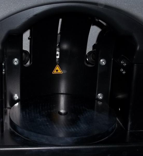
... from some salvaged dental-scanners I've got their 'positioning plate', what's essential a glass-plate with arrays of white dots on a black coating.
This is the raster-plate:
... and this is, what the encoding camera gets:
With this sort of grid-array they calculate the XY-displacement and angular orinatation with an accuracy down to 5 microns and similar angular accuracy ...
Viktor
--------
Aufruf zum Projekt "Müll-freie Meere" - [reprap.org] -- Deutsche Facebook-Gruppe - [www.facebook.com]
Call for the project "garbage-free seas" - [reprap.org]
This is the raster-plate:

... and this is, what the encoding camera gets:

With this sort of grid-array they calculate the XY-displacement and angular orinatation with an accuracy down to 5 microns and similar angular accuracy ...
Viktor
--------
Aufruf zum Projekt "Müll-freie Meere" - [reprap.org] -- Deutsche Facebook-Gruppe - [www.facebook.com]
Call for the project "garbage-free seas" - [reprap.org]
|
Re: Photo-lithography Projector October 29, 2014 10:18PM |
Registered: 10 years ago Posts: 13 |
Hi Victor,
At 5 microns, you're down to semiconductor feature size of a few years ago. Quite amazing for a hobby maker.
The large dots you show clearly form a staggered array. The small ones seem semi-random. The image being looked at?
I was suggesting a simpler, more mundane idea. Just a track of columns of four bits along each axis in four long rows the length of the axis, embedded as tiny dots on the lead shaft of each axis.
Maybe you're suggesting an all-in-one solution for 3D location? Dots on the build platen? Maybe with dots on the underside of a glass platen registered to those above?
Kent
|
Re: Photo-lithography Projector October 30, 2014 03:34AM |
Admin Registered: 16 years ago Posts: 13,886 |
Hi Kent,
this grid-plates are a bit 'overdefined', as they are meant for encoding 3 dimensions, so they designed a tri-/hexagonal grid with the small dots as binary identification.
The camera is positioned below centre of the working area, pointing upwards - the plate is on the underside of the tool-holder and is positioned/aligned manually on the turning table ... see the attached images.
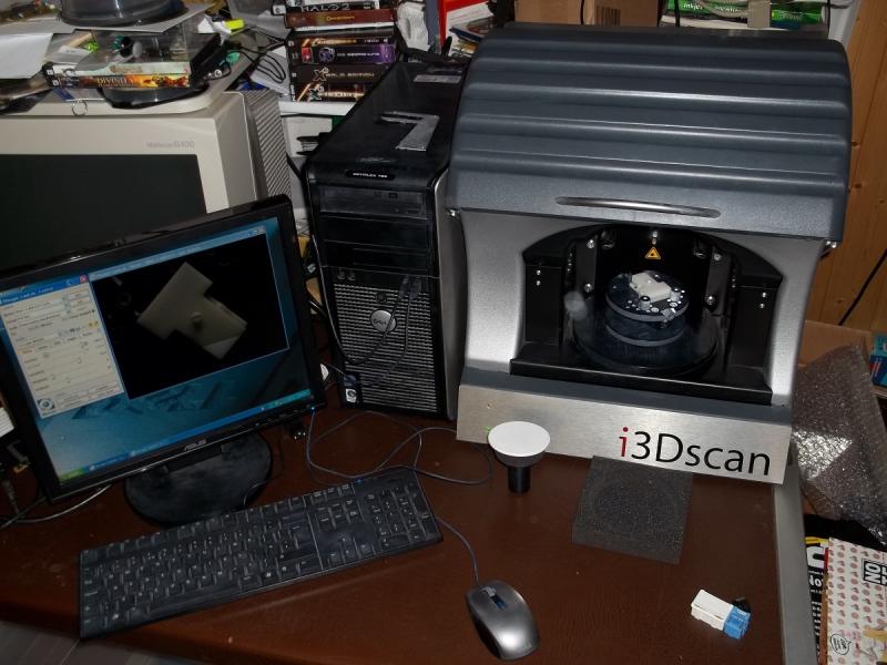
I'm converting one of the 3D-scanners to a sort of mini SLS system with a galvo-scanner and a high-power laser ... but this will take a while ...
This positioning encoding with etched+painted glass can too be done in only one dimension (or two for XY) with a then simpler identification raster (e.g. with the 4x4 grid) ... but the methode would be basically the same ...
Viktor
--------
Aufruf zum Projekt "Müll-freie Meere" - [reprap.org] -- Deutsche Facebook-Gruppe - [www.facebook.com]
Call for the project "garbage-free seas" - [reprap.org]
this grid-plates are a bit 'overdefined', as they are meant for encoding 3 dimensions, so they designed a tri-/hexagonal grid with the small dots as binary identification.
The camera is positioned below centre of the working area, pointing upwards - the plate is on the underside of the tool-holder and is positioned/aligned manually on the turning table ... see the attached images.
I'm converting one of the 3D-scanners to a sort of mini SLS system with a galvo-scanner and a high-power laser ... but this will take a while ...
This positioning encoding with etched+painted glass can too be done in only one dimension (or two for XY) with a then simpler identification raster (e.g. with the 4x4 grid) ... but the methode would be basically the same ...
Viktor
--------
Aufruf zum Projekt "Müll-freie Meere" - [reprap.org] -- Deutsche Facebook-Gruppe - [www.facebook.com]
Call for the project "garbage-free seas" - [reprap.org]
|
Re: Photo-lithography Projector October 30, 2014 09:15PM |
Registered: 10 years ago Posts: 13 |
|
Re: Photo-lithography Projector October 31, 2014 03:54AM |
Admin Registered: 16 years ago Posts: 13,886 |
Quote
kentmcn
Hi Viktor,
I'm trying to get a grip on the system you showed. I have no context with this sort of gear (or application).
Are the three hex patterns in the device located on different physical levels?
Is the camera stereoscopic?
... no, it's a simple plane grid-raster with unique position infos - local positioning and tilting info is calculated with the big dots, the global position (and absolute angular orientation) is extracted from the 'semi-random' distribution of the smal dots.
While the mentioned 4x4 grid is a simple XY encoding version with orthogonal displacement, in this hexagonal raster the smallest area is a triangle, so the small dots are arranged in a triangular grid, defining the base for orientation (see the single small dot right-above every big dot) and then a unique binary raster for the global identification.
An adoption for the RepRaps could be a camera on the printhead, pointing upwards and a raster-plate as 'roof' above, covering the complete building area ...
Viktor
--------
Aufruf zum Projekt "Müll-freie Meere" - [reprap.org] -- Deutsche Facebook-Gruppe - [www.facebook.com]
Call for the project "garbage-free seas" - [reprap.org]
|
Re: Photo-lithography Projector December 09, 2014 12:40AM |
Registered: 9 years ago Posts: 2 |
Sorry, only registered users may post in this forum.