BOLTS, a standard parts library for OpenSCAD and FreeCAD
Posted by jreinhardt
|
BOLTS, a standard parts library for OpenSCAD and FreeCAD November 08, 2013 10:32AM |
Registered: 12 years ago Posts: 50 |
Hi everybody,
in the last few months I worked on a standard parts library for open source CAD tools. The idea is that much of the data you need to create a standard part are things like dimension tables and standard names. The idea of BOLTS is to collect this information in a human and machine readable format and reuse it to easily create standard part libraries for different CAD tools with. You can learn more about it on its webpage:
[jreinhardt.github.io]
In the current version (0.2) BOLTS has support for OpenSCAD and FreeCAD, and contains parts following over 135 different standards (although many of these are for washers, because I used this as a test case during development). A browsable reference about all the parts provided by BOLTS is generated automatically:
[jreinhardt.github.io]
BOLTS is still in the early stages of development. There are many ways in which you can contribute to BOLTS, by adding data, creating geometries or generating drawings:
[jreinhardt.github.io]
If you try it, I would like to hear about your experiences, suggestions and ideas for improvements
|
Re: BOLTS, a standard parts library for OpenSCAD and FreeCAD November 08, 2013 05:20PM |
Registered: 13 years ago Posts: 485 |
|
Re: BOLTS, a standard parts library for OpenSCAD and FreeCAD November 09, 2013 01:40PM |
Registered: 12 years ago Posts: 50 |
The data (dimension tables, ...) is stored in YAML files, so I see no problems that would prevent one to write a interface to your CAD application in the language of your choice. The particular geometries of the parts however are not specified, so it would be necessary to add parametric representations of the parts to the mix in a form that the CAD application understands.
BOM functionality is definitely on my list of things I want BOLTS to do, and some of the information required for that is already provided. However, the particular way to realise a BOM mechanism is highly specific to the CAD system.
Edited 1 time(s). Last edit at 11/09/2013 01:43PM by jreinhardt.
BOM functionality is definitely on my list of things I want BOLTS to do, and some of the information required for that is already provided. However, the particular way to realise a BOM mechanism is highly specific to the CAD system.
Edited 1 time(s). Last edit at 11/09/2013 01:43PM by jreinhardt.
|
Re: BOLTS, a standard parts library for OpenSCAD and FreeCAD November 10, 2013 11:02PM |
Registered: 13 years ago Posts: 485 |
YAML files... learn something new every day.
I'm not sure about other systems, but for SolidWorks it might be easiest (and most useful) to import the data into spreadsheets which SolidWorks can use to generate multiple configurations of a part that has been modeled. That's my tool of choice, so I'll see what I can do with it.
I'm not sure about other systems, but for SolidWorks it might be easiest (and most useful) to import the data into spreadsheets which SolidWorks can use to generate multiple configurations of a part that has been modeled. That's my tool of choice, so I'll see what I can do with it.
|
Re: BOLTS, a standard parts library for OpenSCAD and FreeCAD November 11, 2013 05:28AM |
Registered: 12 years ago Posts: 50 |
I do not know SolidWorks, so I do not know how BOLTS could be best integrated. But is there no standard parts library in SolidWorks? I thought the commercial packages usually have that.
One possibility (that would also benefit other CAD packages) is to create STEP files for all parts. This results in a huge number of files as e.g. a simple bolt has a length and a diameter, and one would need to cover all combinations. Apparently STEP can also represent parametric dimensions which would reduce this problem, but FreeCAD can not do that yet.
So in summary, I am interested in supporting other CAD packages, but SolidWorks or STEP export is not high priority for me right now. However if you want to work on SolidWorks support, I am happy to support you.
|
Re: BOLTS, a standard parts library for OpenSCAD and FreeCAD November 11, 2013 04:38PM |
Registered: 13 years ago Posts: 485 |
SolidWorks does offer a standard hardware library, but it costs extra. Back when we started with SolidWorks (2000), it was a 3rd party add-on that we didn't think was worth what it cost at the time. We developed our own library. Since that was all done for work, I shouldn't use it for hobby projects or distribute it. So, I like the idea of developing a FOSS library for SolidWorks. I considered STEP files for each possible size, but as you point out, that's a lot of files. I did some experimentation in SolidWorks years ago, and I didn't like working with individual files for each size. Instead, what SolidWorks calls configurations are better to work with. Basically, imagine a parametric part containing every variation. For this task, the configurations would be driven by a spreadsheet of parameters saved internally to the file. From there, it's easy to modify the metadata to work with a user's BOM (not standardized by SolidWorks). A macro could then be written (if it doesn't already exist) to export STEP files for every size for those who want that.
I had a browse through some of your data last night. Some component pages presented a very useable table of data. Others seemed incomplete, or possibly stored in a way my browser didn't retrieve. For example, I saw aluminum extrusions that referenced Bosch-Rexroth, but there was no drawing showing profiles. I'm a bit of a Github noob. Is there a way to know which components have data complete enough to be implemented?
How do you handle the enormous number of sizes available that may not be controlled by a standard? For example, socket head cap screws have a huge variety of lengths available for a nominal diameter, but no specified maximum length. For my own work so far, I have taken McMaster-Carr here in the US to be a reference of what is commonly available. Another question is how to handle shapes that are not specified by a standards. Certain features of snap rings are left to manufacturer's discretion.
|
Re: BOLTS, a standard parts library for OpenSCAD and FreeCAD November 12, 2013 05:38AM |
Registered: 12 years ago Posts: 50 |
So it seems that these configurations are the way to go for SolidWorks. If I understand correctly, someone would need to model the geometry in a parametric way, and we need to get the data from BOLTS YAML files into the spreadsheats in SolidWorks. It seems SW can read excel files, so I think there should be a way.
I handle non-standardized sizes by letting the user specify it freely. This is obviously a problem with STEP files, because there are infinitely many different possibilities for such a free parameter. Could you do that with SolidWorks configurations? If not I would need to think about a way of storing common values for free parameters in my YAML files.
I am aware that some parts are missing data. I have no access to real standard documents, so I get the dimensions usually from vendor websites that provide tables or drawings. The urls of these websites are stored along with the data in the YAML file, and can be found as "source" on the page for each part. Maybe I should place that information more prominently.
For the Bosch-Rexroth profiles the source of the dimensions is [www13.boschrexroth-us.com]
The essential information (names, tables, free parameters, ...) should be there for all parts. The authoritative source for this is the blt file for each collection, everything else is generated from this. They can be found here and should be self-explaining:
[github.com]
Additionally I want to have a drawing for the website that shows the basic shape of the part, along with all the parameters (especially the free parameters that the user needs to specify) in a consistent way. The generation of these drawings is half automated (http://jreinhardt.github.io/BOLTS/doc/general/drawing.html), but I did not yet get round doing it for all parts. There is a generated list of missing drawings and parts that are not implemented for some of the supported CAD systems:
[jreinhardt.github.io]
Contributions are always welcome, and you do not need GitHub at all:
[jreinhardt.github.io]
The "short introduction" and "development with git" links should explain everything in (I hope) understandable way.
|
Re: BOLTS, a standard parts library for OpenSCAD and FreeCAD November 12, 2013 09:28AM |
Registered: 13 years ago Posts: 485 |
It sounds like you've been collecting data the same way I have. Frustrating at times, but I guess you just have to deal with that if you don't want to spend thousands on it.
Adding new configurations is very easy, so adding a new size for something that's not in the library is easy enough. Even if someone is working from STEP files, altering an existing model to create a new size once in a while shouldn't be too bad.
It looks as though the data are stored in tables, so import to spreadsheets should be easy. I just need to set aside some time to work out the process.
|
Re: BOLTS, a standard parts library for OpenSCAD and FreeCAD November 12, 2013 11:37AM |
Registered: 12 years ago Posts: 50 |
I would like to have the general process as automated as possible, and also as upstream oriented as possible. The reason for the first is that this allows to handle large amounts of data, avoids neglected and forgotten stuff and makes frequent releases painless. The reason for the second one is that I want information to flow back as much as possible. If someone is adding some data to a configuration it is likely that this information is useful for other members as well. So there should be a easy way of contributing this information back to BOLTS.
How do you distribute configurations? Can you have them in files? Can one generate such files without access to SW? Or is it more realistic to have a bunch of geometries as files and, table data and a macro in SW that creates configurations from that?
How do you distribute configurations? Can you have them in files? Can one generate such files without access to SW? Or is it more realistic to have a bunch of geometries as files and, table data and a macro in SW that creates configurations from that?
|
Re: BOLTS, a standard parts library for OpenSCAD and FreeCAD November 12, 2013 11:35PM |
Registered: 13 years ago Posts: 485 |
Configurations are stored in the model files, and the spreadsheet serves as an editing interface and/or as storage external to the model file. The parameters spreadsheet may be imported multiple times to update the model with changes. So, spreadsheets could be distributed to update model files with configurations. These spreadsheets have some specific formatting that SolidWorks uses to recognize the beginning of the data and to know which data to assign to which parameters in the model. That can be done outside of SolidWorks, but the model's parameters need to be named the same as those listed in the spreadsheet. It's easiest to develop the model first, then export a nearly empty spreadsheet to be populated and them re-imported.
Configured model files can be created entirely programmatically. Some component vendors distribute models of things like linear actuators as macros that create the model files on the user's workstation.
-----------------------
Making changes to installed library components is something to be very careful about. Especially changes to topology. CAD systems like FreeCAD and pretty much all the commercial MCAD systems have assembly modeling systems that can create parametric relations between components. For example, a screw may be constrained to always be in a hole. Those constraints rely on identifying faces (or edges, or vertices, etc.) in the components to establish those relationships. So, if the modeling kernel's internal ID for the faces involved in the constraint changes, every instance of that component that had a constraint on the face will now have an error in the assembly and the constraints will need to be repaired manually. If there is some change to be made that requires a topology change, I'd recommend treating the revised component as a new thing, and not replace existing files in the library. For the library we generated at work, the set screw file has a 4 at the end of the file name, indicating the 4th revision. If we hadn't added that to the file name, projects that used the previous versions would have been broken by the new file. Systems with configured files (I don't know if FreeCAD has this) will have similar constraints on configuration names. Changing the names of configurations in an update will cause errors the next time an assembly referencing that component is loaded.
Pushing out component updates may also break metadata used to populate a BOM, unless there is some translation mechanism which can give the metadata correct labels for each user. For example, "Description" as a metadata label isn't what a user in France is going to want to use in their BOM. I'm not aware of a commercial library that handles this situation well. Users generally have to populate the metadata one part size at a time, and updates for anything other than entirely new parts don't happen. In other words, commercial library vendors punted on the whole issue, rather than figure out a tool to help users populate their BOMs correctly.
OpenSCAD has one of it's few advantages here, as library component geometry is generated new, in place, whenever the model is compiled. So a geometry change won't be a problem. Metadata will still need to be managed though. Hang on, does OpenSCAD even have a mechanism for generating a BOM?
With users contributing new component sizes, do you have any plans for marking some components as generally unavailable or deprecated? For example, an M5 x 200 SHCS might be found and added to the library by someone, but not easily, and may in fact be custom. Or something like the M14 thread size, which is included in the standard, but not recommended for common use. I'm thinking this would be a good thing to mark in metadata. Inch hardware might have "USA only" in an "Availability" field, or "for legacy designs only" in a "Deprecation" field. There are similar examples in plumbing fittings. One lovely ironic example is the popularity in Germany of BSPP hydraulic fittings (though they call them by another name). The BSPP stands for "British Standard Parallel Pipe" threads. The threads are inch nominal sizes, and bastard sizes at that. Not used much here in the USA, where inch and metric SAE o-ring fittings are preferred.
Or do you plan to leave this to the individual designers to check on availability and suitability of components they select? I've always though it would be nice to have on record right in the library.
|
Re: BOLTS, a standard parts library for OpenSCAD and FreeCAD November 13, 2013 04:17PM |
Registered: 12 years ago Posts: 50 |
You raise a lot of interesting points. Thank you for your input. I will try to summarize how I understand the SolidWorks situation:
The user would download a set of SolidWorks files with the parametrized geometry (one for each class of files) and a set of corresponding spreadsheets. The user would put all of them in a folder called e.g. BOLTS0.3. To get a certain part (e.g. a M4 washer DIN125A), he opens the DIN125A file and selects somehow the M4 dimensions from the design table. Or does he need to import the spreadsheet first?
One could ship incremental updates as updated spreadsheets, to add new sizes, but should avoid updating the geometries, as this might cause problems. But at the moment I do not plan to have incremental updates for BOLTS, just releases. And from what you write, this might save a lot of problems.
To get a newer version of BOLTS the user would download a new and better set of SolidWorks files and the corresponding new and better spreadsheets and keeps them in a different folder, e.g. BOLTS0.4.
I don't get this sentence, I am a bit confused. Is a configured model file the same thing as a configuration? And a macro like the one for the linear actuator is a alternative way to distribute a class of similar parts, isn't it. I might have caused this confusion by throwing macros in the discussion in the last post.
Further points that are not specific to SolidWorks:
Translations is a good point. I did not think about that yet. But there is not very much that needs to be translated: Metadata labels like "Description"->"Description", "Name" -> "Nom", ... need to be translated once for all parts, and for every part there is only the Name and the Description.
OpenSCAD has no canonical way for generating a BOM. However, nophead had a few good ideas how to hack around that for his Mendel90. He (ab)uses the logging facilities and a bit of python to generate a up to date BOM automatically:
[github.com]
BOLTS for OpenSCAD will use the same or a similar system. Actually it has most of the logging code in place, but I have to add the postprocessing and document and polish the feature.
About deprecation: At the moment I have the possibility to mark a standard as withdrawn. Such a standard is the marked on the website (http://jreinhardt.github.io/BOLTS/html/bodies/DIN.html), and in the widget in FreeCAD, and OpenSCAD throws a warning and suggests the successor standard, if known. I have not yet a way of deprecating or marking certain parameter sets within a standard as deprecated, or not recommended, but this is a good idea. I will certainly add a way to specify limits on free paramters, but need to think of a good way how to specify not recommended combination in a maximally flexible way.
I am not so sure about a "availability" or "deprecation" field, as this is kind of subjective. And the more fields one offers or even requires, the greater the chance that one gets incomplete or inconsistent data. I think one has to assume to a certain degree that people that use BOLTS know what they want and what they do not want.
The user would download a set of SolidWorks files with the parametrized geometry (one for each class of files) and a set of corresponding spreadsheets. The user would put all of them in a folder called e.g. BOLTS0.3. To get a certain part (e.g. a M4 washer DIN125A), he opens the DIN125A file and selects somehow the M4 dimensions from the design table. Or does he need to import the spreadsheet first?
One could ship incremental updates as updated spreadsheets, to add new sizes, but should avoid updating the geometries, as this might cause problems. But at the moment I do not plan to have incremental updates for BOLTS, just releases. And from what you write, this might save a lot of problems.
To get a newer version of BOLTS the user would download a new and better set of SolidWorks files and the corresponding new and better spreadsheets and keeps them in a different folder, e.g. BOLTS0.4.
Quote
Configured model files can be created entirely programmatically. Some component vendors distribute models of things like linear actuators as macros that create the model files on the user's workstation.
I don't get this sentence, I am a bit confused. Is a configured model file the same thing as a configuration? And a macro like the one for the linear actuator is a alternative way to distribute a class of similar parts, isn't it. I might have caused this confusion by throwing macros in the discussion in the last post.
Further points that are not specific to SolidWorks:
Translations is a good point. I did not think about that yet. But there is not very much that needs to be translated: Metadata labels like "Description"->"Description", "Name" -> "Nom", ... need to be translated once for all parts, and for every part there is only the Name and the Description.
OpenSCAD has no canonical way for generating a BOM. However, nophead had a few good ideas how to hack around that for his Mendel90. He (ab)uses the logging facilities and a bit of python to generate a up to date BOM automatically:
[github.com]
BOLTS for OpenSCAD will use the same or a similar system. Actually it has most of the logging code in place, but I have to add the postprocessing and document and polish the feature.
About deprecation: At the moment I have the possibility to mark a standard as withdrawn. Such a standard is the marked on the website (http://jreinhardt.github.io/BOLTS/html/bodies/DIN.html), and in the widget in FreeCAD, and OpenSCAD throws a warning and suggests the successor standard, if known. I have not yet a way of deprecating or marking certain parameter sets within a standard as deprecated, or not recommended, but this is a good idea. I will certainly add a way to specify limits on free paramters, but need to think of a good way how to specify not recommended combination in a maximally flexible way.
I am not so sure about a "availability" or "deprecation" field, as this is kind of subjective. And the more fields one offers or even requires, the greater the chance that one gets incomplete or inconsistent data. I think one has to assume to a certain degree that people that use BOLTS know what they want and what they do not want.
|
Re: BOLTS, a standard parts library for OpenSCAD and FreeCAD November 15, 2013 10:24AM |
Registered: 13 years ago Posts: 485 |
SolidWorks things:
The spreadsheet must be imported first. Then configurations can be selected. (Configurations can exist without a spreadsheet, but I see no advantage for this application.) Importing the spreadsheet would be necessary for the first use of each model class. Metadata field name translation could be managed by hand at this time by editing parameters in the spreadsheet before importing. An Excel (the only supported spreadsheet) macro that could update them all with translation at install time would be very desirable, and may not be too much coding effort. The same macro could also import the translated spreadsheets into the model files. I could try to do that, but I'm not sure my coding skills are up to it.
When I wrote "configured model", I meant a model with multiple configurations. These can be distributed as macros that create the model with all configurations and metadata. I only mentioned it for completeness. I would think it would be easier to create the models in the particular target CAD system than write and debug macros for it. Maybe I think that just because I'm not a very good programmer. The component vendors who do this use a commercial product that translates some kind of master macro code to the API of each target system.
Non-SolidWorks:
I was thinking this might be the conclusion you reach. I would like to have it, but I can see that it's a little ambitious. The concept of a components "library" would begin encroaching on "design guide".
Name and description are only the beginning of metadata labels that need to be translated, I think. Users may also want to create tables for something like assembly instructions that do not include the full description. For example, M5x20 SHCS may be sufficient, where the full description should cite the standard, material, material class, and finish. Being able to generate various options as the user requires in a table means that a translated name for each piece of information is required. Name, nominal size, length, class, material, finish, standard name, etc. The enormous variety of materials, classes and finishes may present a problem.
The spreadsheet must be imported first. Then configurations can be selected. (Configurations can exist without a spreadsheet, but I see no advantage for this application.) Importing the spreadsheet would be necessary for the first use of each model class. Metadata field name translation could be managed by hand at this time by editing parameters in the spreadsheet before importing. An Excel (the only supported spreadsheet) macro that could update them all with translation at install time would be very desirable, and may not be too much coding effort. The same macro could also import the translated spreadsheets into the model files. I could try to do that, but I'm not sure my coding skills are up to it.
When I wrote "configured model", I meant a model with multiple configurations. These can be distributed as macros that create the model with all configurations and metadata. I only mentioned it for completeness. I would think it would be easier to create the models in the particular target CAD system than write and debug macros for it. Maybe I think that just because I'm not a very good programmer. The component vendors who do this use a commercial product that translates some kind of master macro code to the API of each target system.
Non-SolidWorks:
Quote
jreinhardt
I am not so sure about a "availability" or "deprecation" field, as this is kind of subjective. And the more fields one offers or even requires, the greater the chance that one gets incomplete or inconsistent data. I think one has to assume to a certain degree that people that use BOLTS know what they want and what they do not want.
I was thinking this might be the conclusion you reach. I would like to have it, but I can see that it's a little ambitious. The concept of a components "library" would begin encroaching on "design guide".
Name and description are only the beginning of metadata labels that need to be translated, I think. Users may also want to create tables for something like assembly instructions that do not include the full description. For example, M5x20 SHCS may be sufficient, where the full description should cite the standard, material, material class, and finish. Being able to generate various options as the user requires in a table means that a translated name for each piece of information is required. Name, nominal size, length, class, material, finish, standard name, etc. The enormous variety of materials, classes and finishes may present a problem.
|
Re: BOLTS, a standard parts library for OpenSCAD and FreeCAD November 15, 2013 11:01AM |
Registered: 12 years ago Posts: 50 |
I had a stab on STEP export yesterday, and came surprisingly far. I think I will try to get this ready. As the roadblocks are similar for SolidWorks support, we could try to do see what we can do, if you want.
If I understand correctly, the first step would be to generate Excel Spreadsheets from the BOLTS data in a form that SW understand. If you can tell me how such a spreadsheet should look or provide me with an example, I can see what I can do. Maybe for the beginning for a simple part, like a washer
[jreinhardt.github.io]
I also created a issue in GitHub about SolidWorks support.
[github.com]
For translations, I keep this in mind, but it is not first priority. I think it should be not so difficult to export all translateable strings to one of the popular localisation formats and set up a community based translation. This is the beauty of having things in a machine readable format.
Edited 1 time(s). Last edit at 11/15/2013 11:31AM by jreinhardt.
|
Re: BOLTS, a standard parts library for OpenSCAD and FreeCAD November 17, 2013 08:50PM |
Registered: 13 years ago Posts: 485 |
Example spreadsheets? Sure. I have three I built up from when I did my SolidWorks version of Prusa i2. I built these on my own time so my employer would have no claim on them. Of course, my work library is much more extensive, and full of legacy mistakes. It's nice to start over from a clean slate sometimes.
The SHCS file has some data to the right of Column P that I use as lookup tables when building these by hand. The nut and washer are much simpler models.
Notice that cell A2 is named "Family". SolidWorks looks for this named cell to tell it where the data it needs begins. The help file describing how to prepare a spreadsheet does not mention this, so it may be possible that SolidWorks will make assumptions if it's not there. A blank column to the right, or a blank row below the parameter data signal the end of data. Anything outside those boundaries will be ignored by SolidWorks. Blank cells within the data are to be avoided, of course, but I can't remember what SolidWorks does with them. Most likely, it uses the parameter data in the model configuration active when the new configuration is created by inserting the table. Versions of SolidWorks since I last did that may give an error. In the case of metadata (SolidWorks calls user-accessible metadata "Custom Properties"), blank cells result in nothing being added to the model.
The leftmost column is the configuration name. This is what the user sees when selecting the configuration used by an instance of the model in an assembly.
Cells directly to the right of the cell "Family" contain the parameter names that must correspond to parameters in the model. Parameter names in the form $prp@[name] describe a metadata field.
SolidWorks' help files are available on-line if you want to dig deeper. Spreadsheets used to define configured parameters are called "design tables". The help pages for design tables begin here.
That's all I can think of to tell you about these up front. I'll gladly answer any questions I can.
|
Re: BOLTS, a standard parts library for OpenSCAD and FreeCAD November 19, 2013 05:15AM |
Registered: 12 years ago Posts: 50 |
Hi,
thank you for the example spreadsheets, they were helpful.
I hacked together a proof of concept script that writes an excel file using the excellent xlwt library from [www.python-excel.org]. I attach the one resulting from the BOLTS data on DIN934. Could you please check whether this works.
If this works than it is very easy to export the BOLTS data to Design Tables automatically, the proof of concept was only around 50 lines of python. I will continue working on a proper implementation.
What will be needed for each part is a model file for the geometry and a kind of manifest file that specifies the filename of the geometry, the mapping between SolidWorks parameter and metadata names and the BOLTS parameter names.
BOLTS organizes its parts in "classes", a set of similar parts sharing a geometry, like the different sizes of a nut. A class can describe several standards, there are many identical standards (harmonized or reissued ones). Additionally a geometry can be used by several classes. I have written about that in a bit more detail here:
[jreinhardt.github.io]
For the SolidWorks export this raises the question how we want to handle that. I see several possibilities:
* Duplicate the geometries, so that each standard has its own specific model file and design table. This would result in like 18 identical model files for washers. I do not like this idea
* Have individual design tables for each standard, but share the geometries. If I understand correctly, the user would need to reimport the design tables to use parts from a different standard. The design tables of standards of one class would be duplicated.
* Have one design table for each geometry. These tables could get rather long as they contain all standards for classes that use this geometry. So there would not only be nuts according to DIN 934, but also ISO4032, ANSI B18.2.2, ... Some entries would be duplicated, because some of the standards are identical. However there might be issues if amount and type of metadata that is offered differs between classes.
I would like to keep the amount of duplication as low as possible, especially in not-generated files, therefore I do not like possibility 1. I do not know the usability tradeoffs in SolidWorks to decide between the other two.
BOLTS does not yet contain a lot of metadata, it focuses on the parameters necessary to determine the geometry. So it does not know about pitches, materials or finish like your files do, but there is no technical reason why this could not be added.
|
Re: BOLTS, a standard parts library for OpenSCAD and FreeCAD November 20, 2013 09:12AM |
Registered: 13 years ago Posts: 485 |
Success!
It didn't take a minute to model up a nut using the parameter names in the spreadsheet. Working in SolidWorks 2011 today, but that would have worked on anything since... 98 or so.
Edited 1 time(s). Last edit at 11/20/2013 09:14AM by Dale Dunn.

It didn't take a minute to model up a nut using the parameter names in the spreadsheet. Working in SolidWorks 2011 today, but that would have worked on anything since... 98 or so.
Edited 1 time(s). Last edit at 11/20/2013 09:14AM by Dale Dunn.
|
Re: BOLTS, a standard parts library for OpenSCAD and FreeCAD November 20, 2013 10:35AM |
Registered: 13 years ago Posts: 485 |
TL;DR: I like option #2.
The question of whether or how to merge standards within a class is a tough one. I'm going to ramble a bit on this, so you can see some of my thought process and not just my conclusions.
SolidWorks has a perfectly serviceable component instance replacement tool (replace an instance of a file with an instance of another). A replacement is seamless, and assembly constraints are preserved if the components have identical geometry (copies of the same file, so entity names are the same) or use named mate references ("mates" are assembly constraints). So, to change a component from one standard or material to another can be accomplished with the replace tool.
Something I've tried to avoid in creating my own libraries has been components with enormous numbers of configurations. I have one I use quite a lot for work that has nearly 1000 configurations (SHCS, inch and metric, all the same material and finish). Selecting or changing a configuration requires scrolling through this enormous list, and can be a little frustrating sometimes. I once tried splitting that file into separate files for nominal sizes, but it turns out that using component replacement to change sizes was more hassle than scrolling through the long list. So, too many files is also a burden. The trick is figuring out when to split a hardware class into multiple files.
I've returned to large numbers of configurations in fewer files, but I wouldn't want to take that as far as including every possible standard nut in a daily use nut model. I don't think it will be a common use case to use similar components from different standards, so it would seem to make sense to have different standards in separate files. Material and surface finish are also usually common across whole projects, so that would be a potential place to maintain separate files. Or not. I could go either way on material and finish.
One of the beauties of open source is that users will be able to override design decisions made now if they want to merge or split files, just by manipulating spreadsheets and copying files. Normal SolidWorks operations, I would say. No programming required. I'm pointing this out because I'm not sure a single decision would be optimal across all part classes or use cases. For parts with fewer configurations, I throw everything into one file. For parts with many combinations of size, length, material, finish, etc., I split them up. User preference will the deciding factor, so it should be left to the user to split files if desired. As a user, I think I would choose to have the standards in separate files, with every combination of geometry, material and class, and surface finish in the same file. I think that would be the best balance of out-of-the-box usability and user customizability. Your option #2.
I'm not sure what to do with geometrically identical standards that have not been unified in something like an ISO standard. Where possible, an engineer should specify a unified standard so those buying components will have the largest number of options to pull from. This is increasingly important with globalization. I spec hardware for designs (in the broad class of industrial machinery) that will be built here, but replacements need to be available in China, Poland, Mexico, etc. But what about standards that have been harmonized but not unified? Geometrically compatible but not formally identical? I have a few cases where they are in the same file, but sharing configurations. That is, the standard metadata for each configuration contains references to DIN, ISO, and ASME, instead of having separate configurations for each. I don't see an easy way for the Bolts project to handle that. I think the best way for engineers to handle that (and what I should probably do myself), is to specify the standard most likely to be available, and rely on the builders and service techs to be aware of and work out the compatibility and interchange. Modern standards bodies are all aware of each other, and generally avoid similar naming conventions for incompatible standards. That is, an M5 nut is generally compatible with M5 screws, no matter which standards are referenced.
Looking back on this, it seems that most of my concerns have to do with ease of selection and correct usage, and very little to do with implementation of design tables.
|
Re: BOLTS, a standard parts library for OpenSCAD and FreeCAD November 20, 2013 10:38AM |
Registered: 12 years ago Posts: 50 |
Very nice!
What remains to be done until we got a complete "BOLTS for SolidWorks":
* I need to think of a file format for the manifest file (".base file"), so that the parameter names for design tables can be easily configured
* I need to write a backend for BOLTS that generates the Excel design tables in a controllable and robust way from the backend independent data that BOLTS contains (in the ".blt files") and the .base files
* People with access to SolidWorks need to model the geometries that are necessary to represent all the parts in BOLTS. Currently there are parts with about 20 different geometries, most of them very simple (nuts, bolts, washers).
* The parameter names for every SolidWorks model file are written down in the .base files
* To create a release, the model files and freshly generated design tables are bundled up into a zip file or something, ready for the user to download and use
The model files and base files are checked into the git repository of BOLTS, so that people can work on them without much hassle.
If SW models are not available for all geometries, this is no big deal, then BOLTS for SolidWorks just does not provide these parts. BOLTS for FreeCAD and BOLTS for OpenSCAD are both not complete. If someone needs these parts badly, he/she can just contribute a model for this geometries, the rest is taken care of by the automatic machinery, no manual labour required.
I will start to work on the first two points, maybe get something working already this week.
|
Re: BOLTS, a standard parts library for OpenSCAD and FreeCAD November 20, 2013 10:50AM |
Registered: 13 years ago Posts: 485 |
Further thoughts on the user's selection process.
Some metadata, especially pitch, will be necessary for minimum functionality across all platforms, I think. Especially for users who can't free themselves from inch hardware, where multiple pitches of a nominal size are much more commonly used.
You may have noticed in my example files that my configuration names used fixed-width numerical values. I started doing this so the numbers would appear as if in columns when presented in a list of configurations. Visually scanning the list with variable width numbers was enough of a problem that I went to the trouble to change the formatting in all my commonly used component files. I hope you have a way to implement this, and not just for SolidWorks users. I also order the content of configuration names by importance of selection criteria. For example, nominal size is first in the configuration name, followed by, length, material, and finally finish. I would think that users from any platform that have to choose from a list would appreciate these. More work for the project, I know, but these are features I would request.
There is a way in SolidWorks ("Configuration Publisher") to allow selection by individual parameters rather than from the full configuration list, but it has so far been more trouble than I thought it was worth. This is something else the user can add if desired, I think. I should investigate this further to make sure, and to see if the usability has improved since I last tested it. It's implemented in each model file, so it would be something for the SolidWorks model contributors to add. Not a programming task.
Edit:
The component description does not need to appear in the configuration name. In the case of our hex nut test case, "Hexagon Nut" is unnecessary and in fact, undesireable. Component instances in the "Feature Manager Design Tree" (what SolidWorks calls the branching UI for managing part and assembly model entities) usually are followed by the configuration name. So these need to be kept as short as possible to avoid using more screen space than necessary. So the user would see "Hexagon Nut (Hexagon nut DIN934 - M8)". Abbreviations are helpful too. I would prefer descriptions and file names like this: "Hex Nut". A configuration name might be "M08x1.25, Cls. 8.8 Steel, Nickel Plated, DIN934". Per other discussion, the standard name may be in the description and file name, but shouldn't be in both places.
Edited 1 time(s). Last edit at 11/20/2013 11:11AM by Dale Dunn.
|
Re: BOLTS, a standard parts library for OpenSCAD and FreeCAD November 20, 2013 11:15AM |
Registered: 13 years ago Posts: 485 |
Quote
jreinhardt
...
I will start to work on the first two points, maybe get something working already this week.
Wow. I didn't think this was such a priority. I'll try to set aside some time to model up some parts in a similar timeframe.
The manifest file generates the design table spreadsheets at the local install? For translation and customization. OK, cool. I definitely need to get some models ready to test with.
|
Re: BOLTS, a standard parts library for OpenSCAD and FreeCAD November 20, 2013 02:15PM |
Registered: 12 years ago Posts: 50 |
Quote
Dale Dunn
Some metadata, especially pitch, will be necessary for minimum functionality across all platforms, I think. Especially for users who can't free themselves from inch hardware, where multiple pitches of a nominal size are much more commonly used.
This is something that has to (and can) go into the blt file. I life in metric land, so I never had to deal with multiple pitches.
Quote
Dale Dunn
You may have noticed in my example files that my configuration names used fixed-width numerical values. I started doing this so the numbers would appear as if in columns when presented in a list of configurations. Visually scanning the list with variable width numbers was enough of a problem that I went to the trouble to change the formatting in all my commonly used component files. I hope you have a way to implement this, and not just for SolidWorks users. I also order the content of configuration names by importance of selection criteria. For example, nominal size is first in the configuration name, followed by, length, material, and finally finish. I would think that users from any platform that have to choose from a list would appreciate these. More work for the project, I know, but these are features I would request.
The fixed width numerical values are easily done, for me it is just a matter of changing a character. Sorting like you describe it is also on my list and should be doable without too much effort.
Quote
Dale Dunn
There is a way in SolidWorks ("Configuration Publisher") to allow selection by individual parameters rather than from the full configuration list, but it has so far been more trouble than I thought it was worth. This is something else the user can add if desired, I think. I should investigate this further to make sure, and to see if the usability has improved since I last tested it. It's implemented in each model file, so it would be something for the SolidWorks model contributors to add. Not a programming task.
This sounds like something that could be useful if we choose to put different standards for the same kind of part into one table (like ISO4035, DIN439B, ISO4032, DIN934, ANSI B18.2.2, ASME B18.2.2 for nuts), which then would get very long. If this "Configuration Publisher" would allow to filter this list conveniently, then this might be a good way to do it.
Quote
Dale Dunn
The component description does not need to appear in the configuration name. In the case of our hex nut test case, "Hexagon Nut" is unnecessary and in fact, undesireable. Component instances in the "Feature Manager Design Tree" (what SolidWorks calls the branching UI for managing part and assembly model entities) usually are followed by the configuration name. So these need to be kept as short as possible to avoid using more screen space than necessary. So the user would see "Hexagon Nut (Hexagon nut DIN934 - M8)". Abbreviations are helpful too. I would prefer descriptions and file names like this: "Hex Nut". A configuration name might be "M08x1.25, Cls. 8.8 Steel, Nickel Plated, DIN934". Per other discussion, the standard name may be in the description and file name, but shouldn't be in both places.
Again technically no problem, we just have to figure out the best way.
Quote
Dale Dunn
Wow. I didn't think this was such a priority. I'll try to set aside some time to model up some parts in a similar timeframe.
I realised that it is not as much effort as I had thought. And I think BOLTS can benefit from that by improving the infrastructure and opening it for another audience.
Quote
Dale Dunn
The manifest file generates the design table spreadsheets at the local install? For translation and customization. OK, cool. I definitely need to get some models ready to test with.
No, the design tables get generated when I create a release. The user downloads a zip file with xls design tables and model files, never gets in contact with anything else. For translation one would probably generate individual design tables for each language.
|
Re: BOLTS, a standard parts library for OpenSCAD and FreeCAD November 20, 2013 03:52PM |
Registered: 13 years ago Posts: 485 |
Quote
jreinhardt
...
No, the design tables get generated when I create a release. The user downloads a zip file with xls design tables and model files, never gets in contact with anything else. For translation one would probably generate individual design tables for each language.
So, there is no explicit facility for different users or organizations to apply their own metadata field names? It's a little worse than 1:1 translation. For example, some organizations might use "Name" where we have been using "Description", and "Description" instead of "Size". Will the tools you use to create the spreadsheets be published so users can generate these variant designations? If not, some quick googling shows me there is freeware to do batch find & replace in multiple Excel files. OK. I can accept either. Probably the find & replace will be easier for most users, since SolidWorks users should be conversant with using design tables this way.
|
Re: BOLTS, a standard parts library for OpenSCAD and FreeCAD November 20, 2013 04:10PM |
Registered: 12 years ago Posts: 50 |
|
Re: BOLTS, a standard parts library for OpenSCAD and FreeCAD November 27, 2013 08:44AM |
Registered: 12 years ago Posts: 50 |
Hi again,
I did not manage to finish the SolidWorks Backend last week, a bit of refactoring turned out to take longer than expected. But now I think I got most of the exporter done.
To setup a table for generation, one needs a model file (lets call this one nut.model for the sake of this explanation) and a base file (the manifest) and put it into the folder corresponding to the collection from which parts are to be exported. In this case this would be solidworks/nut
The basefile is a YAML file again (so indentation matters) and looks like this:
The filename gives the model to which this table belongs. The author and license fields give the author and license of the model file. The name of the table file will reflect which model it belongs to, but different tables for one model can be created by choosing a different suffix for each.
The params and metadata fields give the mapping from the solidworks parameter names to the BOLTS parameter names which can be looked up in the blt files or on the specificaton pages of a part (like here ). In this case this is not a useful one, because the blt files contain not much useful metadata yet.
The classes field gives the list of classes to use. For each the class id has to be given, which can be looked up in the blt files or on the specification page of the collection (like here. Additionally a naming element can be supplied that allows to customize the form of the configuration name. If not given, the standard naming of the class is used.
This allows to be quite flexible in the selection of classes to include in a designtable, the form of the configuration names and the name and selection of parameters and metadata. I believe this satisfies most of the points that we discussed.
What is not yet implemented is the proper sorting of the entries in the table.
The resulting table is attached, and should be usable with the nut file that you created earlier.
I did not manage to finish the SolidWorks Backend last week, a bit of refactoring turned out to take longer than expected. But now I think I got most of the exporter done.
To setup a table for generation, one needs a model file (lets call this one nut.model for the sake of this explanation) and a base file (the manifest) and put it into the folder corresponding to the collection from which parts are to be exported. In this case this would be solidworks/nut
The basefile is a YAML file again (so indentation matters) and looks like this:
---
- filename: nut.model
  author: Johannes Reinhardt
  license: CC0 1.0 [creativecommons.org]
  type: "solidworks"
  suffix: ISO
  params:
    Size@Sketch1: d1
    Width@Sketch1: s
    Thickness@Boss-Extrude1: m_max
  metadata:
    $prp@MetaTest: e_min
  classes:
   - classid: hexagonthinnut1
     naming:
       template: ISO4035 - %s
       substitute: [key]
   - classid: hexagonnut1
     naming:
       template: ISO4032 - %s
       substitute: [key]
...
The filename gives the model to which this table belongs. The author and license fields give the author and license of the model file. The name of the table file will reflect which model it belongs to, but different tables for one model can be created by choosing a different suffix for each.
The params and metadata fields give the mapping from the solidworks parameter names to the BOLTS parameter names which can be looked up in the blt files or on the specificaton pages of a part (like here ). In this case this is not a useful one, because the blt files contain not much useful metadata yet.
The classes field gives the list of classes to use. For each the class id has to be given, which can be looked up in the blt files or on the specification page of the collection (like here. Additionally a naming element can be supplied that allows to customize the form of the configuration name. If not given, the standard naming of the class is used.
This allows to be quite flexible in the selection of classes to include in a designtable, the form of the configuration names and the name and selection of parameters and metadata. I believe this satisfies most of the points that we discussed.
What is not yet implemented is the proper sorting of the entries in the table.
The resulting table is attached, and should be usable with the nut file that you created earlier.
|
Re: BOLTS, a standard parts library for OpenSCAD and FreeCAD November 27, 2013 09:31AM |
Registered: 12 years ago Posts: 50 |
Ah, and another question. Do you have any idea how copyright and license issues apply to the case of the SolidWorks configurations?
For example consider the case that someone contributes a model file that is licensed under GPL. Now someone creates a larger model or a assembly that contains configurations derived from the GPL model file. Does he have to license the larger model or assembly under the GPL as well?
If this were the case (and in my not-law-trained opinion this is the case) then I would have to require all SolidWorks model files contributed to BOLTS to be in the Public Domain or [creativecommons.org], otherwise this would constrain the usefulness of BOLTS very much. But considering that most model files should be very simple, I think this is not a big deal.
|
Re: BOLTS, a standard parts library for OpenSCAD and FreeCAD November 27, 2013 12:40PM |
Registered: 13 years ago Posts: 485 |
Another successful test. The metadata test also worked fine.
The line:
- filename: nut.model
Should probably read:
- filename: nut.sldprt
If it ever becomes necessary to do an assembly (I have done nut and washer stack assemblies), the filename extension would be ".sldasm".
Can parts of different files have different licenses? I'm not really sure that's possible. I was reading the section on licenses on the bolts site last week and wondering what use any of these models would be if not released to the public domain or CC. If a license prevents users from including the models in deliverables to a customer, then Bolts will only be useful to hobbyists, and only hobbyists who agree to the restrictions of the license. If it never grows beyond OpenSCAD, FreeCAD, maybe Blender or a few other FOSS tools, that might be OK. If someone uploads a restricted model I want to use, I would take the time to make another using CC. As you say, the models are too simple not to. The data in the tables is the really valuable item.
Things I still want to see in the spreadsheet:
-Configuration names with most significant data at the front (SolidWorks sorts alphanumerically after import).
-Fixed width numbers in the configuration name.
Things I need to get done:
-Some model files to work with existing classes.
-Learn to make base files.
-Maybe add metadata to some blt files so we can work up a complete test.
How do you plan to handle parts with different geometric features? For example, a set screw (some say "grub screw") may have a variety of point types (flat, cone, etc.). So far, I've handled that in configurations with the different point features, with the inapropriate features suppressed. (A suppressed feature is analogous to code that is commented out to prevent it from compiling.) From what I've seen so far, you would want to handle that as a separate class. But there are some components (retaining rings) that would belong in the same class but require a different shape for different sizes.
What is the distinction between parameters and metadata? Do they need to be handled separately?
I'm leaving this afternoon for the long holiday weekend here in the US, so I won't be able to pay any attention to this until next week.
|
Re: BOLTS, a standard parts library for OpenSCAD and FreeCAD November 27, 2013 01:09PM |
Registered: 12 years ago Posts: 50 |
Quote
Dale Dunn
Can parts of different files have different licenses? I'm not really sure that's possible. I was reading the section on licenses on the bolts site last week and wondering what use any of these models would be if not released to the public domain or CC. If a license prevents users from including the models in deliverables to a customer, then Bolts will only be useful to hobbyists, and only hobbyists who agree to the restrictions of the license. If it never grows beyond OpenSCAD, FreeCAD, maybe Blender or a few other FOSS tools, that might be OK. If someone uploads a restricted model I want to use, I would take the time to make another using CC. As you say, the models are too simple not to. The data in the tables is the really valuable item.
Ok, so you agree with my take on the topic: Stuff that gets combined with user content must be public domain or CC0, otherwise BOLTS gets too restricted.
Quote
Dale Dunn
Things I still want to see in the spreadsheet:
-Configuration names with most significant data at the front (SolidWorks sorts alphanumerically after import).
-Fixed width numbers in the configuration name.
All this already works then. You can use the naming field to customize the generated configuration name to your liking. For example, to have the thread size before the Standard, you would use "%s ISO4032" in the template field. To get fixed width numbers, you can use field width specifiers like "%5.2f". All format specifications provided by pythons can be used [docs.python.org].
Base files are simple text files. You can create and edit them with any editor like notepad or gedit or kate. The blt files are also plain text.
Quote
Dale Dunn
How do you plan to handle parts with different geometric features? For example, a set screw (some say "grub screw") may have a variety of point types (flat, cone, etc.). So far, I've handled that in configurations with the different point features, with the inapropriate features suppressed. (A suppressed feature is analogous to code that is commented out to prevent it from compiling.) From what I've seen so far, you would want to handle that as a separate class. But there are some components (retaining rings) that would belong in the same class but require a different shape for different sizes.
For the grub screw I would not want separate classes. I see no problem in having a number of different geometries for one class, controlled by a parameter. Both the python functions used of FreeCAD geometries and the modules used for OpenSCAD can handle that. If SolidWorks can handle that as well, all is good. The radial ball bearing is such an example already present in BOLTS for FreeCAD. There you can choose between shielded and open bearings.
Quote
Dale Dunn
What is the distinction between parameters and metadata? Do they need to be handled separately?
From the BOLTS side there is no distinction, everything is a parameter. I had the impression that for SolidWorks there is a distinction, namely the form of the column header. I decided to make the distinction in the base file. This way one can write automatic syntax checks and distinguish the cases that a class does not provide some of the metadata (should be fine) and that a class does not provide a parameter (should give an error).
I hope you enjoy your long weekend and the turkey.Quote
Dale Dunn
I'm leaving this afternoon for the long holiday weekend here in the US, so I won't be able to pay any attention to this until next week.
|
Re: BOLTS, a standard parts library for OpenSCAD and FreeCAD December 09, 2013 09:41PM |
Registered: 13 years ago Posts: 485 |
|
Re: BOLTS, a standard parts library for OpenSCAD and FreeCAD December 10, 2013 03:41AM |
Registered: 12 years ago Posts: 50 |

|
Re: BOLTS, a standard parts library for OpenSCAD and FreeCAD January 08, 2014 07:07AM |
Registered: 12 years ago Posts: 50 |

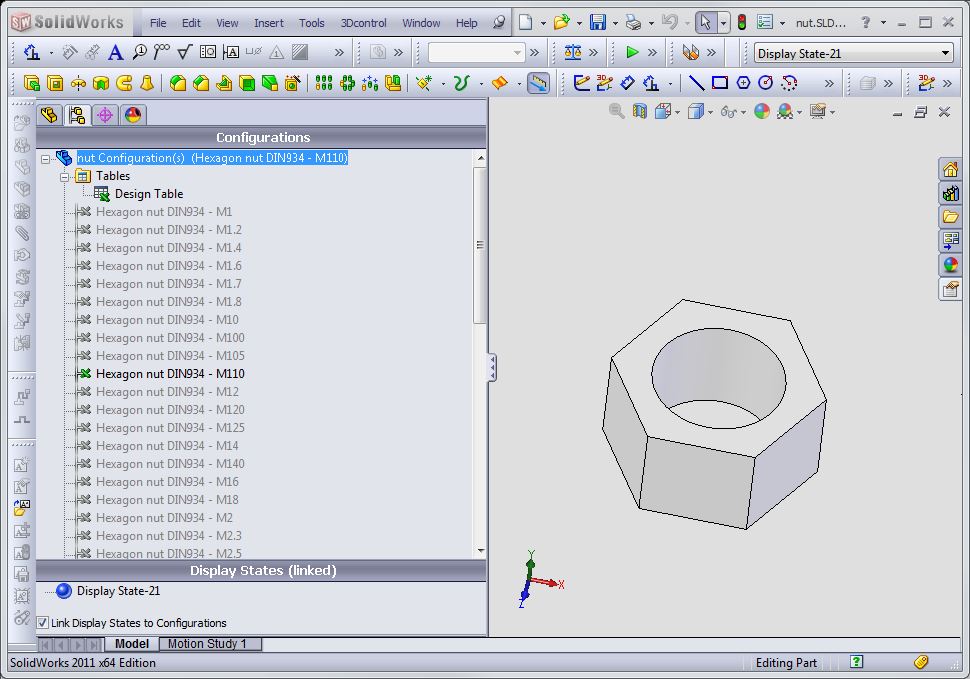
Sorry, only registered users may post in this forum.