How to use AutoBedLeveling for CNC stock surface mapping ?
Posted by UnLtdSoul
|
How to use AutoBedLeveling for CNC stock surface mapping ? November 08, 2017 03:34AM |
Registered: 8 years ago Posts: 7 |
I use Marlin with a Ramps board to control my CNC machine, its been working great. But, I do a lot of V-carving of signs on edge glued pine boards. The wood is never true and flat. I don't have a planner (and most of the boards I use are 17-20" wide), and i don't want to hassle with CNC leveling each board - so, what I want to do is use the ABL feature to map the surface of the board, and apply that when V-Carving. I configured my configuration.h file to enable it, and i've made a limit sw i can quickly attach to the spindle (I use a touch plate hooked up to Z-min to find the top surface height of the stock using gcode G30 command - and the limit switch for surface mapping plugs-in in parallel with the Z-min input).
I know that I can send the G29 command and tell Marlin where X Y start position is, and the stock (bed) max lengths using the B (back) F (Front) L (left) R (right) tags.
I got it set up, but, haven't tried it yet, because I am not sure how to set it up any further, or exactly how Marlin will apply this relative to a CNC setup. The limit sw (probe) isn't going to be the same Z length as the various bits - so, the height map the G29 reads is not going to be the exact top of the surface of the material when i replace the limit sw with the cutting Bit and run the G30 command to get the surface height of the stock. So, after i run a G29 command, how do i give the Z offset between the map readings and the G30 surface height reading?
Hopefully someone can understand what i am getting at.
What I see the code needs to do is create a map of the surface where the Left Front (x y corner of the stock material) would be Zoffset of 0 and the the mapped heights will all be relative (same or higher or lower) than the first reading. Then, i would put in the cutting bit and run a g30 at the same X Y corner - getting the actual stock height at that corner. Then as it carves the wood it will adjust Z height according to the map. That is how i see this needs to work. So, is that how Marlin's ABL works by default, or will I need to go into the Cpp code and make my own hack to the code? (which i am willing to do)
|
Re: How to use AutoBedLeveling for CNC stock surface mapping ? December 01, 2017 05:29AM |
Registered: 8 years ago Posts: 15 |
I'm trying to do the same thing. As for the probe, I made a 3D print, attached to the spindle shaft. The whole system is working except that when I change the tool in the middle of the job and try to do a zprobe (g30), the leveling information is lost. As you can see in the video below, I do homming just in the Z, before starting the leveling ...
[1drv.ms]
[1drv.ms]
|
Re: How to use AutoBedLeveling for CNC stock surface mapping ? December 01, 2017 09:44AM |
Registered: 8 years ago Posts: 7 |
ProSoft - OK so fill me in on how you are using the ABL feature. I never got it set up on my system yet, because i was thinking that the way Marlin works it won't work for CNC use, but, it looks like it is for you. Your switch is aligned to your bit (spindle shaft) in the X Y directions. So you need no XY offset, but, it is below the bit in the Z direction. So, how do you compensate for that? Where do you set the Z offset? My probe is also offset in the X and Y direction, and in the Z direction. So, where and how do i set those offsets? The Z offset will be different for each bit and bit change, so it can't be set to a fixed value.
The problem your having, when you change bit in middle of cut, you have to do a new Z zero setting and you then lose the ABL map. If Marlin has no current setting for that, then when i get the time i will look to see where that can be changed in the code. What I will do is add a setting to the Configuration.h file add a CNC ABL flag that tells marlin NOT to delete Map info after a G30 command. Then I will find out where in the main.cpp file it is resetting the map data during the processing of the G30 command and add code to check for our added flag and NOT reset the data if our flag is set. It should be a fairly easy modification to make. Modifying the Configuration.h file and marlin-main.cpp file.
i would put a comment and mark the added/changed code in the main.cpp file, that way when we update to a later version we can put the same changes in the new updates. I could also submit it for review and see if it can be added to future versions.
so tell me, where / how did you do the Z offset to be able to use the ABL feature? And, if i can, i need to also set an XY probe offset.
|
Re: How to use AutoBedLeveling for CNC stock surface mapping ? December 01, 2017 10:14AM |
Registered: 8 years ago Posts: 15 |
I made some modifications in the marlin and in the postprocessor. In marlin, I deactivated the requirement of homing before leveling. Even so, right at the beginning of the leveling i must first do a Z axis homming. In the postprocessor, i included a few lines to perform leveling (you can add it by hand, for test purpose), more or less this:
(note im using LCD)
G92 X0 Y0 Z0 ; set all to zero if not
M0 Autolevel start ; display text on lcd
G28 Z0 ; home Z
G29 L0 R? F0 B? X3 Y3 T V4 ; here you replace ? by wdth and lenght of you stock in mm - in general postprocessor can calc that
M0 Probe remove... ; lcd tells you to remove your probe and turn spindle on, then click to continue
*I'm losing all my hair trying to discover where in the execution of the g30, the leveling information is deleted ...
If im not clear, feel free to post as much questions you want. Im desperate to make it work well
|
Re: How to use AutoBedLeveling for CNC stock surface mapping ? December 01, 2017 10:21AM |
Registered: 8 years ago Posts: 15 |
|
Re: How to use AutoBedLeveling for CNC stock surface mapping ? December 01, 2017 10:31AM |
Registered: 8 years ago Posts: 15 |
|
Re: How to use AutoBedLeveling for CNC stock surface mapping ? December 01, 2017 11:04AM |
Registered: 8 years ago Posts: 7 |
I haven't compiled and ran it yet, but, in the configuration.h file I've added a define - right after the defines to enable leveling:
#define AUTO_BED_LEVELING_BILINEAR
// ADDED following:
#define CNC_LEVELING_G30_KEEP_ALIVE // if defined, then we do NOT cancel leveling after running the G30 command
Then in the Marlin_main.cpp file I've modified the following
ORIGINAL Code
<<<<
// Disable leveling so the planner won't mess with us
#if HAS_LEVELING
set_bed_leveling_enabled(false);
#endif
>>>>
I modified the code as follows:
<<<<
// Disable leveling so the planner won't mess with us
#if HAS_LEVELING && ! CNC_LEVELING_G30_KEEP_ALIVE
set_bed_leveling_enabled(false);
#endif
>>>>
Only if LEVELING has been defined and ! (NOT) CNC_LEVELING_G30_KEEP_ALIVE has NOT been defined it will set bed leveling to FALSE
so, with our KeepAlive flag defined in the configuration.h file it won't disable leveling when you do a G30 command.
You will need to modify the actual Marlin_main.cpp file - if using Ardunio IDE just send the updated file to your controller as normal - it will compile the changes before sending it.
I will try this myself later, but if you try it first, let me know if it works for you
|
Re: How to use AutoBedLeveling for CNC stock surface mapping ? December 01, 2017 12:19PM |
Registered: 8 years ago Posts: 15 |
|
Re: How to use AutoBedLeveling for CNC stock surface mapping ? December 03, 2017 05:25AM |
Registered: 8 years ago Posts: 15 |
|
Re: How to use AutoBedLeveling for CNC stock surface mapping ? December 05, 2017 02:38AM |
Registered: 8 years ago Posts: 7 |
Sorry I was tied up on the weekend.
I didn't really understand the way Marlin worked regarding X Y Z positions, it keeps track of a RAW and a LOGICAL data set. Anyway, that made the whole thing a bit easier.
It looks like I've got a system working. But, I'm not sure the way I use it will be the same as the way you use it.
I use a Z-Max limit sw, so when i issue a G28 or G28 Z cmd, the spindle homes to the Max Z moving the spindle all the way up. My mapping probe is connected to Z-Min input.
My GCODE Header work flow is as follows - in Gcode -- without leveling:
; Beginning of Header
M80; Turn On Power Supply (PC ATX PS = Power for Steppers)
G90 ; ABSOLUTE MODE
g28 Z0 ; home to limit sw
g28 Y0 ; home to limit sw
g28 X0 ; home to limit sw
M3 S8500; turn Spindle On to Snnn RPM
; Move spindle to desired Start Pos - XY corner of the Work piece
; EDIT NEXT 2 LINES
G0 x20 y40 f12000 ; xy corner of material
G0 z132 f1200 ; top of material NOTE: in my set up, ZMAX == 210, so I am moving it down from 210 to 132 (This Value is obtained by running a G30 command and is different with each bit change and material height )
g92 x0 y0 z0 ; set current LOGICAL location to 0,0,0
G0 Z5.080 F1200; Spindle is now 5mm above the XY starting corner of the material.
;----- End Of Header
; --- run the actual Gcode for Cutting ----
So, to use the Surface mapping, here is my new work flow, before I run the above GCode header and cutting file
G28; Home
G0 Xnn Ynn Fnn; send the spindle to the XY corner of the work material, such as X20 Y40
G92 X0 Y0;
G29 L0 F0 Rrr Bbb Xxx Yyy T; Where rr = Right (X) size of work area to map, bb= back or Y size of material to map and X and Y = how many grid points per X and Y for the map if T is given it will print the results out to the serial port so the host software will display it (I am currently using Repetier Host for sending the GCode files)
; I can't use the Defaults for the LFRB at least not for the RB so i must send them with the g29 command, I've included a CNC_LEVELING_VALUES define in the configuration.h file that when enabled, the G29 command either HAS to have
; the LFRB XY values explicitly set, or it will give an Error and not run the mapping. The only exception is you can issue a G29 T and it will not do a map, but, will print out the current map to the serial port
; This will then create the MAP - but, it will calculate the Z Height at whatever Height the Probe is-- which will NOT be the same as the cutting Bit...
; so, after running G29 i move the spindle back to the material XY starting corner, which will be 0, 0 since I used the G92 command to set 0,0 to the work piece corner
G0 X0 Y0 F12000
; remove the Probe and if not already installed, install the router bit,
; then issue G30 command. This will do a single probe at the starting corner of the work piece.
; I have Modified the G30 it not only will not disable the Mapping, but, i've added a value to the configuration.h file called ZERO_PLATE_THICKNESS that you set to the thickness of the TouchPlate
; this way when we do a G30 it will calculate the Z height (-) (minus) the thickenss of the touchplate, so it will get the exact Z height of the work stock at the starting corner.
; the other thing it does, is it will get the Z value of the first map point, 0,0 and get the Difference between the Probed Z at that point, and the Z height of the Bit at that point. That gives me the Z-offset of the bit... so I don't have to calculate it, or set it manually, the G30 will now calculate it for us.
; Then, it will take this Difference value and apply it to all remaining points in the map, adjusting the map for the height of the bit to surface work area. This is all done automatically when we issue the G30 command, as long as CNC_LEVELING is defined in the configuration.h file
; so after this G30 we can then go ahead and run the Gcode script to cut the work piece,
; the Gcode can re-Home the spindle, etc, and the mapping data will still be there and mapping will still be enabled.
; After the first bit is done cutting, if another bit is needed, like a rough cut, then final cut or additional cuts,
; change the bit and move spindle to Starting corner of work piece and issue another G30 with the touch plate in place and it will get the Z height with the new bit - (minus) the thickness of the touch plate, get the difference in height and apply that new
; difference to the map - again, and it is ready to cut with the second bit, you can Home, etc, and cut away. And, you can do this as many times as you need, the map data will not be disabled.
; you can issue a G29 T to view the existing map data.
So far i have only DRY run it, i haven't had time to put on a piece of wood and cut it, but, after mapping, I issue HOME and G30, i can use G0, G1 and move the spindle around (I had purposefully put a board on the work area on a tilt) and as you move around the spindle in the X Y directions, the Z tracks up and down as needed to keep the spindle level to the tilted surface.
I am uploading the Configuration.h and Marlin_main.cpp HOWEVER, these two files were customized previously by someone else for the MPCNC machine. That machine uses 2 steppers for both the X and Y axis, and this modified Marlin controls each stepper individually with separate limit switches on each stepper. So, you may not be able to use the Marlin_Main.cpp I am sending directly, I have noted where i did the changes for the CNC Leveling, so search for "CNC_Added" and copy the code in those areas to the .cpp file that you use. Same with the Configuration.h file. Let me know if this works for you.
|
Re: How to use AutoBedLeveling for CNC stock surface mapping ? December 05, 2017 05:36AM |
Registered: 8 years ago Posts: 15 |
I will try to explain how i use it:
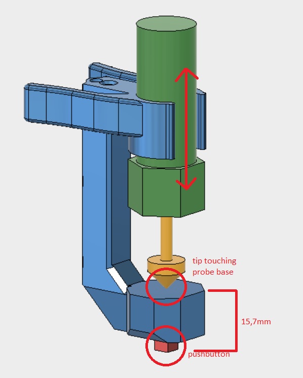
When I turn on the CNC, the tool is already positioned about 30mm above the workpiece at the point of origin (0,0). Its the stock (workpiece) origin, not the machine origem. I never do X and Y homming. I do not even have the endstops installed. After i install the probe that you can see in the vídeo (https://1drv.ms/v/s!AvqTPlo1zPyAkppC1hyFxV9IhIYCFg). It was printed on a 3D printer and has a button down it. I use the probe attached to zprobe_min_z. After the probe is installed, (gcode is paused at this time), I give a click on the lcd to continue the gcode execution. First the homming of the Z (down) is done using the probe against workpiece, then begin the tests of the leveling points. Once the leveling is finished, gcode is paused again and i remove the probe, turn on the spindle and click on the lcd to continue ...
Most of my changes (not all) i marked with a MILLING flag, so you can find then with a search
About probe thickness, you must use
#define Z_PROBE_OFFSET_FROM_EXTRUDER -15.7
in configuration.h
Here, 15.7 is the thickness of my zprobe, that is positioned below the tool tip
If you using LCD, there is a setting for that. You can save it to eeprom
here the aspire 8.1 header that generates my gcode
"G90" ; absolute positioning
"G21" ; mm units
"G92 X0 Y0 Z0" ; set all to zero
"M0 Autolevel start" ; pause and show message to lcd
"G28 Z0" ; home z
"G29 L0 R[XLENGTH] F0 B[YLENGTH] X3 Y3 T V4" ; execute autoleveling
"M0 Probe remove..." ; pause and wait for removing the z probe and turn on the spindle (i do that manually)
"M03" ; gcode to turn on the spindle in case i want to do that automatically in future
"G0 Z[SAFEZ] F20000.0" ; raise to safe height (here i use a super hight feedrate that will be limited by marlin
When I turn on the CNC, the tool is already positioned about 30mm above the workpiece at the point of origin (0,0). Its the stock (workpiece) origin, not the machine origem. I never do X and Y homming. I do not even have the endstops installed. After i install the probe that you can see in the vídeo (https://1drv.ms/v/s!AvqTPlo1zPyAkppC1hyFxV9IhIYCFg). It was printed on a 3D printer and has a button down it. I use the probe attached to zprobe_min_z. After the probe is installed, (gcode is paused at this time), I give a click on the lcd to continue the gcode execution. First the homming of the Z (down) is done using the probe against workpiece, then begin the tests of the leveling points. Once the leveling is finished, gcode is paused again and i remove the probe, turn on the spindle and click on the lcd to continue ...
Most of my changes (not all) i marked with a MILLING flag, so you can find then with a search
About probe thickness, you must use
#define Z_PROBE_OFFSET_FROM_EXTRUDER -15.7
in configuration.h
Here, 15.7 is the thickness of my zprobe, that is positioned below the tool tip
If you using LCD, there is a setting for that. You can save it to eeprom
here the aspire 8.1 header that generates my gcode
"G90" ; absolute positioning
"G21" ; mm units
"G92 X0 Y0 Z0" ; set all to zero
"M0 Autolevel start" ; pause and show message to lcd
"G28 Z0" ; home z
"G29 L0 R[XLENGTH] F0 B[YLENGTH] X3 Y3 T V4" ; execute autoleveling
"M0 Probe remove..." ; pause and wait for removing the z probe and turn on the spindle (i do that manually)
"M03
"G0 Z[SAFEZ] F20000.0" ; raise to safe height (here i use a super hight feedrate that will be limited by marlin
|
Re: How to use AutoBedLeveling for CNC stock surface mapping ? December 05, 2017 08:27AM |
Registered: 8 years ago Posts: 7 |
Well, i started to look at your mod's, and i see that we are taking 2 totally different approaches. If what you have is currently working, but, you mainly want to keep the mapping from getting disabled, it is being disabled in the G28 processing, try bypassing line 3743 in Marlin_main with you ck for the Milling define. That should keep the mapping from getting disabled.
I also think the mods i made should work for you as well, if you don't need or use G30 it will still work.
BUT, i set my code to enable this only using Bilinear ABL, the bypass in G28 should work with any ABL process.
Your using a -15.7mm Probe Z offset, which I assume is the offset using an installed bit, but, won't that change when you change out your bit? So, you would have to know what that offset is of the changed bit??? and change it, right?
Unless you are mounting the switch bracket directly to the bit? and the sw is set at 15.7mm below the tip of the bit, no matter what length of the bit is?
But, if you wind up needing to remeasure and reset the Z Probe offset after you change out a bit, then you should consider adding wiring for a touch-plate and use the G30 command. It uses the same Z-min inputs, i have the touch-plate wires and the Z probe limit sw wires in parallel, they both trigger the same Z-min input.
I just realized as i am writing this, i should probably change my G30 code.... What i am having the G30 code do is find the Z Probe offset, and instead of just setting that value to the Z Probe Offset variable, i am going in and applying the offset directly to the mapped data points. I mean, it works, but, it is is kinda dumb since there is a Z Probe Offset variable, i think all i need to do is set the difference to that variable. Whatever, it is a minor change.
But, if you don't need to remeasure and reset the Z Probe offset, and just keeping the map data enabled is really all you need, take a look at the code i have in the G28 processing part.
|
Re: How to use AutoBedLeveling for CNC stock surface mapping ? December 05, 2017 09:41AM |
Registered: 8 years ago Posts: 15 |
Quote
UnLtdSoul
Your using a -15.7mm Probe Z offset, which I assume is the offset using an installed bit, but, won't that change when you change out your bit? So, you would have to know what that offset is of the changed bit??? and change it, right?
Unless you are mounting the switch bracket directly to the bit? and the sw is set at 15.7mm below the tip of the bit, no matter what length of the bit is?
But, if you wind up needing to remeasure and reset the Z Probe offset after you change out a bit, then you should consider adding wiring for a touch-plate and use the G30 command. It uses the same Z-min inputs, i have the touch-plate wires and the Z probe limit sw wires in parallel, they both trigger the same Z-min input.
Did you take a look at the video I posted the link to? The probe I use works as if it were a touchplate, only attached to the spindle shaft, but it slides up so that it always rests against the tip of the tool. That way, I do not have to keep holding the touchplate under the tool during the autolevel. So, I just need to tell z_offset to compensate for its height. Before I used a touchplate made of PCB ... My goal is to join our two codes. I believe that the way I do autolevel is more practical, but the way I do zprobe does not work. If we can put the two together and organize the code, I think it will be very good. If I understand you correctly, you do the autolevel manually. Do you use LCD or use a computer connected to USB?
This afternoon i will take a time to read carefully all your post...
|
Re: How to use AutoBedLeveling for CNC stock surface mapping ? December 05, 2017 06:04PM |
Registered: 8 years ago Posts: 15 |
Quote
UnLtdSoul
Well, i started to look at your mod's, and i see that we are taking 2 totally different approaches. If what you have is currently working, but, you mainly want to keep the mapping from getting disabled, it is being disabled in the G28 processing, try bypassing line 3743 in Marlin_main with you ck for the Milling define. That should keep the mapping from getting disabled.
As soon as I start work, I do z homming and self-leveling (G28 and G29). So far so good. The problem I have, is when I need to swap the tool in the middle of the job, and do a zprobe (G30). From there, the autoleveling information is lost.
That's just what I want to do (G30)Quote
UnLtdSoul
I also think the mods i made should work for you as well, if you don't need or use G30 it will still work.
Quote
UnLtdSoul
Your using a -15.7mm Probe Z offset, which I assume is the offset using an installed bit, but, won't that change when you change out your bit? So, you would have to know what that offset is of the changed bit??? and change it, right?
Quote
UnLtdSoul
Unless you are mounting the switch bracket directly to the bit? and the sw is set at 15.7mm below the tip of the bit, no matter what length of the bit is?
But, if you wind up needing to remeasure and reset the Z Probe offset after you change out a bit, then you should consider adding wiring for a touch-plate and use the G30 command. It uses the same Z-min inputs, i have the touch-plate wires and the Z probe limit sw wires in parallel, they both trigger the same Z-min input.
It basically Works as a touchplate, stick to tool tip (see attached image)
|
Re: How to use AutoBedLeveling for CNC stock surface mapping ? December 05, 2017 08:38PM |
Registered: 8 years ago Posts: 7 |
I took a look at your Marlin_main.cpp file again, wanted to look at your G30 code, and I am not seeing the function. What used to be the gcode_G30() function is now called old_gcode_G30()
I do see in the old_gcode_G30 code it does appear that you are bypassing the code that disables Mapping, but, I'm not seeing how that code gets run.
But, in my mod, G30 doesn't disable mapping. Rather i have it modify the mapping data, not disable it.
I do see in the old_gcode_G30 code it does appear that you are bypassing the code that disables Mapping, but, I'm not seeing how that code gets run.
But, in my mod, G30 doesn't disable mapping. Rather i have it modify the mapping data, not disable it.
|
Re: How to use AutoBedLeveling for CNC stock surface mapping ? December 06, 2017 07:00AM |
Registered: 8 years ago Posts: 15 |
Its because i have made many tests with gcode_g30() and nothing works as i want.
I want to execute a zprobe (G30) without lose the autoleveling data but had no success until now.
Inside gcode file i do this
1. Set mm, set absolute positioning, set XYZ to zero,
2. Execute homming (only Z down, using the probe as endstop)
3. Execute autobed leveling
4. Start milling
Up to here, all went well.
Now i need a tool change
6. Lift tool and go to XY origin (0,0)
7. Change tool (manually)
8. Do a zprobe (G30) to correct new tool lenght and have a nice height to start working again
9. Resume milling
Here i get a wrong leveling. I see Z not more react to workpiece level and milling now is flat on Z (autobed leveling is lost)
This is my problem. Dont matter what i change in gcode_g30() i cannot avoid deleting the autobed level data.
|
Re: How to use AutoBedLeveling for CNC stock surface mapping ? December 06, 2017 07:03AM |
Registered: 8 years ago Posts: 15 |
|
Re: How to use AutoBedLeveling for CNC stock surface mapping ? December 06, 2017 05:39PM |
Registered: 8 years ago Posts: 552 |
|
Re: How to use AutoBedLeveling for CNC stock surface mapping ? December 07, 2017 05:18AM |
Registered: 8 years ago Posts: 15 |
Sorry, only registered users may post in this forum.