Prusa I3 BOM Help
Posted by Zerker
|
Re: Prusa I3 BOM Help September 28, 2014 01:08AM |
Registered: 11 years ago Posts: 72 |
|
Re: Prusa I3 BOM Help September 28, 2014 09:00PM |
Registered: 10 years ago Posts: 167 |
cheers, I'll get some glass when I get paid next week, and grab some Firegum at the same time, Repco says it's $7.99 inc GST
got the belts attached this weekend, had trouble getting them tight, will have to install the nuts and bolts for the belt tensioners after all, there is not enough belt to give full range of motion and add a peg spring on the belt. had to take off the Z threaded rod on the belt tensioner side to get the bolt in to attach the idler, apparently I had forgotten to do this and it was just sitting in there, a good thing though as I had to take it out and cut the sides of the bolt head down to get clearance between the bolt and the Z threaded rod.
not much left to do just waiting on parts and time
|
Re: Prusa I3 BOM Help October 16, 2014 09:00PM |
Registered: 10 years ago Posts: 167 |
Took a couple days off work and got some time in the garage, did not complete anywhere near enough of the printer, spent most of the time off riding around town trying to get supplies.
I should now have everything I need except filament.
Fans are tiny but will blow enough air to do the job, most of the fan is taken up by the central hub, tis a shame but I guess you get what you pay for, the fans sold locally are possibly better quality.
I wont post the link for supplier of the fans as the service was right crap. had to raise a dispute with them as they insisted the tracking number they issued was legit when it never tracked through NZ post, it was only traceable through chinapost.
Firegum comes in a gigantic tube, once I'm done I may give the remainder away.
finding someone to cut flat glass was a hassle, 4 different places before I found someone who would cut it and it was pricier than I had imagined, I will always get quotes online before going looking now, one would think that a product like cut flat glass should be a snap to walk in and get.
Mint Glass off of Te Rapa Straight in Hamilton cut me a piece of 4mm for $10.00
Finally got around to EDL to get the bolts to hold the extruder idler closed, cut the 8MM threaded rod for the idler to spin on, and cut springs to size, it turns out that the 4mm Washers have enough oversize to let the washer slid over the spring and the holes on the extruder are oversized as well. when I cut the springs down I flattened out part of the last coil so it cant go under.
Extruder motor gear has a whole on the bottom to act as a nut trap however I only had 4mm Nylock nuts and did not fancy another trip out, so I widened the hole a little with a box knife and then melted in the nut with my soldering iron, a delicate procedure to be sure, and I'm no surgeon. once the Nut was in it was still hot and continued to warp/melt the plastic making it wide enough that the nut would still turn within the hole, covered the nut with some 2 part epoxy, and it works a treat now, extruder assembly just needs heater and thermistor to be installed.
got some time to review software and firmware, decided on Pronterface and Marlin, will upload marlin once I double check I've got my driver boards in the right way, don't want to fry anything before I start.
I have also noticed that my Y Frame is no longer square, the feet refuse to sit flat and I cant see an obvious place that is causing it, I will have to sort that soon too.
for now, work work, and I'm expecting to get more time in the garage this weekend, might even take a pic or two.
|
Re: Prusa I3 BOM Help October 19, 2014 08:23PM |
Registered: 10 years ago Posts: 167 |
No pics this time, only got a few hours to work with.
got the RAMPS connected to the laptop, loaded up Marlin and Connected to Pronterface. I plugged in the Extruder motor to the X axis on the RAMPS, got it to move in one direction, I have hot wired up thermistors or endstops yet so the printer was assuming it was at the endstop every time I went to move backwards.
Finally got the Y bed sorted, I had over tightened one side which caused the twist, I had originally planed to have the Motor sit behind the printer however this lead to the motor sitting on the base board for the ZX Frame and keeping the back end of the Y frame off the ground. Had to move the Nuts to the other side of the Y Frame to allow me to turn it around and put the motor out the front. this was good and bad.
Good now the bed gets full range under the X carriage, bad it took me an hour to move all 4 nylock nuts to the other side, I only had open crescents to use, no ratcheting and only a limited range to use the crescent.
attached the HBP and glass to the Y bed, may have to do this again as I think I did not leave enough room on the screws for bed levelling, only a few millimetres.
still to come,
re-doing the threaded rod coupling to the Z motors, need to keep a very small gap between the motor shaft and threaded rod, too long and it just folds and twists.
endstops, wiring up the extruder (thermistor and heater), Tensioners for the belts not sure how I will do this as the printed parts don't seem to have Nut traps. bed needs to be levelled out, attach extruder to X carriage, I've had that on before so should not be an issue.
I will need to get a thermistor at some point for the HBP, for now I will be printing without as I have not purchased a new PSU for my PC to be able to pull out the one in there, the one I have now for the printer does not have enough amperage on the 12V rail to run the heated bed and everything else.
I think I can do all of that next weekend so will plan to buy some PLA for calibration.
Things don't seem to be as tight as I would like them to be, so may be awhile before I'm printing anything useful, for now I'd be happy once it starts pushing out plastic.
|
Re: Prusa I3 BOM Help October 27, 2014 01:46AM |
Registered: 10 years ago Posts: 167 |
"It's almost done, I swear", at least that’s what I told my wife after 2 days in the shed.
Z couple is done for like the third or fourth time, soldered the Z motor wires so they now run in series.
Thermistor and Resistor assembled into the hot end. used Firegum to seal did not have to wrap the resistor in foil as it was a nice fit, resistor comes up to temp nice and fast and cooked the fire gum.
Extruder is all assembled and re-attached to the x carriage. Tested the cold end and it pushes filament through by hand, have not had a chance to push it through with the motor yet.
Wired all end stops and homed all axes. Though they are not yet in their final positions, X can come across a bit further; Y can mount to the back instead of the front of its mount to give a tiny bit more Y length. Z is still too high off the Bed to allow for printing, I will work on this soon.
So what’s left to do? Everything moves and the printer gets up to temp right?
No, the thermistor for the hot end has stopped working, I think when I homed X the cables got in the way of the end stop and may have resulted in a broken link in the Thermistor, I taped up all wires coming from the X Carriage so they would run smooth over the frame and have not had a chance to separate out the wires to see if there is a break or if I need a new thermistor.
I may also need to print a new small gear, the bolt that I cut down to fit this has been cut too short and also the gear split around the whole. The extruder doesn't seem to care though as the gear continues to move just fine so I hope to get through calibration prints and make this my first official print.
oh and the wife is on board a bit, she paid for the PLA I will be using, picked the colour too (Ruby Red...I must not complain, must.. not)
next weekend i plan to have prints to show even if they are just spagheti monstors. anyone know what thermistor i will need to get? I've just gor the one that came with my Jhead.
|
Re: Prusa I3 BOM Help October 27, 2014 09:46PM |
Registered: 10 years ago Posts: 167 |
Yup, Definatly a broken thermistor, both of the wires cam eloose, and when I went to re-attach one of the wires broke right at the glass bead, i need to get another, this one is unsalvagable, anyone got an idea for a local supplier?
this is the closest match i can find
[nz.element14.com]
this is the closest match i can find
[nz.element14.com]
|
Re: Prusa I3 BOM Help October 27, 2014 11:11PM |
Registered: 10 years ago Posts: 167 |
Never mind about the Thermistor, I just got a PM from reifsnyderb who runs www.hotends.com and he advised that the replacement for the one that came with the Jhead is not available through nz.element14, and advised he will send me some, I even explained how it was my fault it broke, was happy to send a replacement anyway.
it should take about 2 weeks for it to arrive form the states, but I'm happy to wait knowing I'm getting the exact part i need
it should take about 2 weeks for it to arrive form the states, but I'm happy to wait knowing I'm getting the exact part i need
|
Re: Prusa I3 BOM Help November 03, 2014 07:08PM |
Registered: 10 years ago Posts: 167 |
Adding up spend so far, I spent US$292.99 (NZ$ current 378.75) on parts from china and US, and a further, NZ$133.34 on parts, this figure has some rounding in it, don't has a guess for the Frame, I don't have the receipt as to how much I actually spent for the end frame (did not count the failed plywood frame build cost) as I don't have the receipt and I bought tools at the same time.
I also had to buy some consumables like screws and epoxy that is not included, but the rough value is NZ$512.09, not quite the sub $500.00 I was hoping, but if you change out some parts for the now lower cost you can get on aliexpress, you can do this for sub 500.
still waiting for replacement thermistors to arrive, but that's still within expected time frame, will post more once I've received those
|
Re: Prusa I3 BOM Help November 03, 2014 08:48PM |
Registered: 9 years ago Posts: 118 |
That,s not bad,Zerker, mine cost around $540nz for the whole kit,incl.freight.
Having said that,I now have a non-working nozzle heater.I also broke the nozzle thread off,after cleaning it,and refitting to the block.
Heavy in the hand and light in the head .I managed to drill out and retap the block,but the nozzle is toast.
I guess it,s that old story,you get what you pay for.But to be fair,most of the parts of a $3000 printer come from china anyway.
Funnily enough,my kit actually had a spare thermistor included.Didn't think they were that vulnerable.
You must be getting close to a working printer by now?
Edited 2 time(s). Last edit at 11/04/2014 02:54PM by clogs51.
Having said that,I now have a non-working nozzle heater.I also broke the nozzle thread off,after cleaning it,and refitting to the block.
Heavy in the hand and light in the head
.I managed to drill out and retap the block,but the nozzle is toast.I guess it,s that old story,you get what you pay for.But to be fair,most of the parts of a $3000 printer come from china anyway.
Funnily enough,my kit actually had a spare thermistor included.Didn't think they were that vulnerable.
You must be getting close to a working printer by now?
Edited 2 time(s). Last edit at 11/04/2014 02:54PM by clogs51.
|
Re: Prusa I3 BOM Help November 11, 2014 04:33AM |
Registered: 10 years ago Posts: 167 |
yup, pretty close now
got the new termistor installed (arrived yesterday) and set to work with printing the bed leveling STL for calibration, I had trouble with the first Corner it was lifting up and forming a loop then sticking back down to the bed about 3mm later in the X axes.
It took me forever to figure out why, turns out the layer was not adhearing to the bed properly so as the extruder retracted when turning the corner (presumably to prevent oozing) the material that had been laid down, just lifted straight back up again making the loop/hump.
I went out and got some blue painters tape (3M 2090) and put that on the bed and it showed everything that was wrong, the left is too low and the right is too high, I get a line of fillament laid down in the Y direction, it barely sticks down and then when it turns , I get a line to about halfway (no lifting loop yay) and then the nozzle begins to dig into the tape (not enough to have been hitting the glass before i added the tape though so no damage) and then the same in reverse as it goes back, so half the square gets printed, but the left hand Y side of the square lifts easily, the first half of the X sticks just fine.
I need to do a re-think about the stupid way I setup my bed leveling, currently the screw head is under the bed and two nuts above, one under the PCB and one above, this would have lead to the screws poking out above the bed and getting in the way of printing so I cut down the screws, I'll get some more screws and put them in the other way so the nuts are under the PCB and under the bed, i wont trim them this time, leaving lots of room for bed leveling.
no time to do any more on the printer till this weekend, will hopefully be able to move onto the next phase of calibration and the weekend after that I might print something usefull, like spare parts.
Cheers
|
Re: Prusa I3 BOM Help January 01, 2015 10:46PM |
Registered: 10 years ago Posts: 167 |
Long time no post.
been getting a bit of work done over the holidays (new job at work too so I actually get holidays, no more call centre for me, I'm an application specialist (I fix issues for records in the databases that users cant see from the GUI, well till august when the person I'm filling in for returns to work))
I've completed the bed leveling fix I mentioned in my last post, screws now come in from the top, have a nut underneath the PCB holding it tight against the nut, then on goes the spring, the spring then pushes against a washer on the top side of the plywood bed, and then there is one last nut on the underside of the plywood bed.
This nut is then used to make adjustments, as the spring holds tension you need to push down on the head of the screw and then the bottom nut is free to turn up or down to lower or raise that corner of the bed.
I would like to implement auto bed leveling so I can set this to as close as I can get it and then have all prints probe first then increase Z offset during print to allow for any movement.
______________________________________________________
Now on to the trouble I've been having.
First as mentioned in the previous post there is noticeable movement of the hotend when I retract filament during a print, and there was noticeable movement in X and Y on the first prints I did, photos 1 and 2 to get an idea.
I had forgotten to place bolts through the bearing holders on the X and Y Carriage which lead to a lot of free play, I fixed this up by placing some cable ties through these holes and closing them up snug but not too snug.
once I resolve my other issues I plan to print different X and Z bearing holders as these ones are rather fragile due to the layers running down the length of the bearing instead of around, which can result in easy breakage or delamination. I had the first X carriage break in transit due to this and broke the second in assembly which I glued back together.
The cable ties appear to have helped a lot as you can see in pics 3 and 4
____________
Problem number two the above fix had no effect on the movement of the hotend during retraction, I at first figured this was due to the slot mounting as it was lifting up and towards the back of the printer in the direction of the opening of the slot, however if the jhead was snug in the hole for the extruder then this movement would not be possible.
I removed the Jhead and measured the inside of the extruder, due to the cleanup this print had required the internal depth was not uniform and ranged from 8.6 - 10.04mm in depth, much larger than the Jhead's 4.76mm top of the peek for slot mounting, I figure this is a flaw in the design in the extruder as it is designed for both slot mounting and grub screw mounting (guess who doesn't have the grub screws?) so I desided to lay it unsafe and make a spacer.
As this is the cold end of the printer using something like PLA or wood is not a bad idea, PLA would have the potential to rub against the fillament (which at this point will have ridges on it from the hobbed bolt) and could drop more PLA into the hotend, not a problem as it's what I'm printing with anyway but I dont have the design skills yet to make the required object and I've only printed squares, no idea how a circle would go or how the hole in the middle will come out.
So going with the tools and materials I am capable with I decided to be ridiculously unsafe and make a wooden spacer out of MDF.
so I cut a square out marked a 15mm circle, drilled a 5mm hole in the center ( i want this over sized to limit filament rubbing against the wood) converted the square to a circular'ish object with the help of a Vise and a file, cleaned it all up with sandpaper and a light smattering of spray paint in an effort to stop creating dust that could go into the hotend.
Now that is so not the way to do this, you can clog up the nozzle, cause the MDF to get hot on long prints and start a fire all sorts could go wrong.
however I did this knowing all of the above and risking it anyway, I confirmed the hole is over sized, tested for dusting and flaking from filament rubbing and all came out satisfactory, I believe for the short time I plan to have this in here it will be ok, and it will be replaced when I can print a new extruder.
_______________
This brings us to pictures 3 and 4, the edges are far superior to the previous prints and there is very little movement during printing, there is still some during retraction that will be fixed once a new extruder is obtained.
What does appear to be an issue is the feeding of filament.
I currently have a loose roll of filament hanging above the printer suspended from the ceiling of the garage. As filament is feed out tension builds in the coil that is not released until I manually turn the roll and even then I can only slightly release the tension as I'm not moving the filament as a whole, this then causes the extruder to have trouble feeding the filament at the correct rate and also moves the x carriage slightly off track, this should be eliminated by using a roller that I can coil the loose filament onto, unless there are other issues at play.
from the pictures can you see anything else that may be going wrong?
Pic 1
Pic2
Pic3
Pic4
|
Re: Prusa I3 BOM Help January 02, 2015 12:14AM |
Registered: 9 years ago Posts: 118 |
Fwiw,my y-axis uses these:
[www.aliexpress.com]
They are also available at double the length,holding 2 bearings.
I had to take them off the x when i had a new carrier printed for my wade's extruder.
My printer also had a wobbly hotend when first fitting it,I had to put a steel washer on top of the j-head before refitting in the carriage.
I got a similar problem when i found that the thumb screw for bed levelling was coming undone through vibration on longer prints.
This then hit the frame,causing the bed to move sideways at one spot.
I've now removed the thumb screws and fitted ny-lock nuts on all four bed screws.
A bit more of a pain to adjust,but I'm considering auto levelling anyway.
The piece in the middle of pic3 looks pretty good to me.
Edited 1 time(s). Last edit at 01/02/2015 12:17AM by clogs51.
|
Re: Prusa I3 BOM Help January 02, 2015 02:14AM |
Registered: 10 years ago Posts: 167 |
My Y axis seems fine, I've attached the bearings with cable ties directly to the bed and there is no noticeable free play in there
in Pic 3 those three short rods have an error on the right hand side, that line is stringing where the printer goes from one piece to the other, they were printed together.
pic 4 is the same file and again 3 in one print, no stringing between them I'm pretty sure the artifacting is to do with the way the filament feeds in
Edited 1 time(s). Last edit at 01/02/2015 02:16AM by Zerker.
|
Re: Prusa I3 BOM Help January 06, 2015 06:03PM |
Registered: 10 years ago Posts: 167 |
I may have forgotten to calibrate my printer.
Yup egg on face
I started calibration and skipped form bed leveling straight to printing a cube to check that the X Y and Z were working as expected, I was rather worried about the amount of free play in the printer, so worried I completly forgot about other aspects.
I linked one of the above print pictures into the IRC chat last night to see what they thought the problem would be, and got some fatastic responses.
I will be running through triffids calibration guide on the wiki this weekend and hopefully end up with some decent prints.
and for those following along at home, here's the guide
[reprap.org]
|
Re: Prusa I3 BOM Help February 01, 2015 12:16AM |
Registered: 10 years ago Posts: 167 |
Got some more time to spend on the printer and printed more test prints, see latest in link
[imgur.com] image is part of a failed iphone case print, stopped after the first layer, can someone take a look at the piece on the left hand side and tell me what is going on?
the other two pics I'm pretty happy with, if I can sort out what is happeing in the first one I should be about good to go
[imgur.com] image is part of a failed iphone case print, stopped after the first layer, can someone take a look at the piece on the left hand side and tell me what is going on?
the other two pics I'm pretty happy with, if I can sort out what is happeing in the first one I should be about good to go
|
Re: Prusa I3 BOM Help February 01, 2015 02:04PM |
Registered: 10 years ago Posts: 77 |
I'm guessing you are concerned with the non-uniform nature of the long solid runs on the first layer which seem to get better to the right side of the print. You can improve this by making sure the bed is spotlessly clean, perfectly level (compared to nozzle travel), has the right clearance (from the nozzle) and is not running too fast (on the first layer). In my experience, the most important factor is the nozzle clearance. If it is flying too high, the extruded plastic will deposit in blobs rather than a continuous run. You see one line being affected by the previous line to make some interesting patterns. I think your iphone case first layer doesn't look too bad and would probably have come out OK if you let it keep running. If the first layer is a bit blobby, the second and third layers will usually be much better. The important thing is that the first layer is stuck to the bed. Of course for an iphone case you may want the first layer to look beautiful when you lift it off the bed - in which case it is worth chasing perfection. Other parts you print might not be that critical.
My Prusa Mendel i2 inspired Repstrap with welded steel frame: [youtu.be]
And my Smartrap derived Briefcase 3D printer: [youtu.be]
My Prusa Mendel i2 inspired Repstrap with welded steel frame: [youtu.be]
And my Smartrap derived Briefcase 3D printer: [youtu.be]
|
Re: Prusa I3 BOM Help February 01, 2015 05:27PM |
Registered: 10 years ago Posts: 167 |
Cheers
I also asked the reprap IRC chat with a link to the same pics, they said pretty much the same advising that the bed is probably not level and that the nozzle is too close to the bed, that first layer is extremely thin, and it fits with what you wuold expect, as the nozle is too close it is not pushing out all the fillament that is being fed in and you get a build up in pressure that eventuates in the blobbing seen on the left hand side. I will admit my Z endstop is not perfectly fixed to the printer and can move slightly each time the printer homes.
so when I home all after leveling the bed it homes again at the start of the print and possibly lowers the Z by a small amount.
I was thinking the Z was actually rather high until they pointed that out, looking at other peoples first layers they appear to have ridges where the fillament is laid down with a line that shows where each row touches the other, in mine it looks more like a flat line of fillament with raised ridges where each each line touches the other, would you agree? my eyes are not so great that close up lol, or atlest they werent last nigth when I was looking at it
|
Re: Prusa I3 BOM Help February 01, 2015 06:28PM |
Registered: 10 years ago Posts: 77 |
Could be right that the nozzle is flying too low rather than too high. Hard to tell from a photo. One way to work it out properly is to do a large solid square calibration piece and setup the Z so that it is deliberately sloped along the X axis from say 0.1mm to 0.4mm clearance. Use feeler gauges to measure and set the clearance at each extreme of the X travel. Have it levelled on the Y. Set your slicing so that the first layer fill is parallel with the Y axis. Printing a test piece like this, you will see a transition as the first layer progresses from being too little clearance to too much clearance. There will be a bit in the middle that is perfect. You can then work out by linear interpolation, exactly what clearance you need to shoot for to get a perfect result every time. (Or at least till you change filament, temperatures, bed surface , hot end or whatever other variables might affect it).
My Prusa Mendel i2 inspired Repstrap with welded steel frame: [youtu.be]
And my Smartrap derived Briefcase 3D printer: [youtu.be]
My Prusa Mendel i2 inspired Repstrap with welded steel frame: [youtu.be]
And my Smartrap derived Briefcase 3D printer: [youtu.be]
|
Re: Prusa I3 BOM Help February 01, 2015 07:15PM |
Registered: 10 years ago Posts: 167 |
hmn, feeler gauge, now there's a thought.
if I have the Z endstop hard fixed to the bottom of the printer (z motor mount) then have an adjustable probe on the Z axis (a screw with a nylock nut locked in place so the screw turns and the nut does not) then it should be easier for me to level the bed, I can go the route of a feeler gauge if I dont get it with the paper method.
I'm just glad that I've gotten it this far, the prints actually look rather nive all things considered, and I agree the phone case would most likley have come out fine but I wanted to make sure this was not a larger issue first
|
Re: Prusa I3 BOM Help March 30, 2015 11:35PM |
Registered: 10 years ago Posts: 167 |
long-time no progress, after last pics I haven’t wanted to print anything as I was aware of some issues that needed a fair amount of work to resolve and didn’t have the time or inclination to do it, now I've taken two days off work to "Get 'er done" (6 day long weekend)
what I want to get done over this time is:
Re-do bed levelling apparatus
create a Z probe
hard mount the Z endstop
replace wooden spacer in Jhead mounting
Quick question/update before I go off to Bunnings tomorrow morning
I'm going to get rid of the heated bed, I won’t need it and it’s so warped it is probably contributing to my bed levelling problems.
I plan to get a square of MDF or something equivalent to use as the printbed and to clamp the glass to (if I could drill into the glass without losing print volume I'd just do that.
I will then attach the new bed to the bottom tray (the 12mm plywood I have attached the Y axis bearings to) with three bolts so it will look like this from top down:
Head of bolt
washer
MDF bed
Wide washer (glued to previous layer)
spring (larger than the diameter of the nut but smaller than outer diameter of washer)
Nut (glued to next layer)
Wide Washer (glued to next layer)
plywood base
Nut (glued to previous layer)
this way if I need to raise or lower the bed i will just need to turn the head of the bolt, with the spring being larger than the nut and sort of sleeving the whole thing it should not get between the washer and bolt jamming the bolt from moving (which is a current problem)
Aim is to use a large bolt like M6 to make it large enough to get a decent sized spanner on rather than using a screw driver and a pair of pliers that I'm currently using. I will also change to a three point bed levelling, thinking two front one back so that access is easier.
At the same time I plan to look at re-attaching the Y belt to the bed (if I can be bothered, I may have to print a new piece as the one I have in place is rather long) to try and recover some of the Y axis print volume
I will replace the Wooden spacer with a series of washers as spacers instead, I also want to replace the wood that currently holds the Jhead to the extruder body as this is flexible and could be causing issues as well, though the spacers is the big issue as this poses a risk for jamming if any of the wood falls down into the hotend.
For the Z probe it needs to not move but I also don’t want to mess with the Z axis or the X axis as these are working just fine so I will make a permanent attachment to the X motor mount with holes drilled to allow access to the x motor mounting holes should I need to access this later, I will make it in two parts, a flat piece glued to the X motor mount and a bottom piece that comes out in the y axis from the motor mount, and the Probe will be a bolt going through this piece that will go up and down in Z by threading on the nut glued to it.
again like the Bed levelling system, I want to use an M6 bolt and nut, if there is too much free play in this or the thread is too coarse for the amount of increments needed I will revise, but I want the head of the bolt to be easy to hold and turn by hand
XXXXXX
XXXXXX
XXXXXX
XXXXXX
XXXXXX
XX XXX
XXXXXXXXXXXXXXXXXXXX
XX XXXXXXXXXXXXXXXXX
XXXXXXXXXXXXXXXXXXXX
XXXXXXXXXXXXXXXXXXXX
YYYYYYYYYYYYYYYYYYYY
YYYYYYYYYYYYYYYYYYYY
YYYYYYYYYYYYYYYYYYYY
YYYYYYYYYYYYYYYYYYYY
YYYYYY
YYYYYY
YYYYYY
YYYYYY
YYYYYY
YY Y
YY Y
YYYYYY
now for the Z endstop itself I plan to mount it on a piece of wood that will sit underneath the endstop (holes drilled for the wiring) and sit hard against the Z motor mount, this should not allow the Z endstop any room to move and the Z probe shouldn’t move either and I will then be able to control the Z height for the first layer correctly, this is mostly cosmetic compared to the other fixes.
It will also help with bed levelling, currently I'm comparing one corners bed height to a slightly different Z endstop height due to the endstop moving so I never really get it flat.
|
Re: Prusa I3 BOM Help April 07, 2015 01:49AM |
Registered: 10 years ago Posts: 167 |
(Update)
Got less work than expected done (wife did not see the merits of spending all 6 days in the garage, but hey enough about that)
I have replaced the Heated bed with an MDF base and setup the three bolt leveling system, setup a Z probe (I suppose not realy a probe more of a depth stick) and hard mounted the Z endstop.
There have been a few problems but things are working much better than before.
I managed to print a bedleveling.stl which shows the bed is about as level as I can get it and far superior to any first three layers I've ever printed, it even had great stability on Y and X axis with less vibration showing up than before which makes me think the M6 bolts instead of the M3 bolts I was using was a great idea, the stronger springs (C-624 I think) have made an impact as well I would say.
I have noticed that the bed adhesion is not as good as it was before due to the hotend not forcing the first layer into the bed as hard as it was before but I will investigate this as a possible temp/adhesion (gluestick/hairspray) issue instead of layer height (the first and third layer appear to be exactly (well I couldnt see a diff) the same thickness so I dont want to lower it any further if I dont have to)
I still have issues with oozing/over extruding, I want to re-do my E stepps/mm as this is likely the cause, this is hard to test with first layer not sticking to the bed, but I do have another conecern too, when I extrude manually I get a bit of lag time from motor movement to extrudate coming out and then some oozing after. is this a back pressure issue? or is this normal and I'm not retracting enough to compensate?
|
Re: Prusa I3 BOM Help June 04, 2015 08:57PM |
Registered: 10 years ago Posts: 167 |
Update number .... I forget.
The bed levelling is working great and I have re-calibrated my extruder (it was pulling in 32mm when asked to do 30) and also discovered I had setup Slic3r to say I had a 0.4mm nozzle when I actually have a 0.5. this seemed to clean up the prints but only by a small bit.
I noticed that the prints still had a lot of noticeable ridging on the vertical faces which was not due to the extruder, this is more likely due to slack in the printer. Looking over the machine again from the point of view of making everything Tight, I noticed the Y and X belts are slack (I can bend the belt over my finger which if it is as tight as it should be I would not be able to do) First thought was to get some belt tensioner springs but the slack is more than these should be asked to take up so I will detach the belt from one end and tighten them completely with tensioners at their lowest setting and then tighten with tensioner and add a spring after this. I will have to wait for springs to come in but I have to wait for other parts anyway.
I also noticed that when I saw the hotend moving during retraction earlier on it was not just the hotend but the whole X axes that was moving. This was due to loose cable ties on the bearing holders on the X carriage and worst of all so much free play that the X smooth rods could be twisted so they were no longer parallel. this was caused by the X ends being loose on the smooth rods and the Bearing holders for the X ends being loose on the Z axes smooth rods (far too much free play everywhere). This was amplified by the lack of stability on the Box Frame, I made my Box from out of 90mm wide instead of 100mm wide and sat the whole thing on a pane of glass that is not as wide in the X axis as the printer was (this makes the Y and X sit at the same level but leaves the X overhanging so there is less support to stop the box frame rocking backwards and forwards), I plan to make some supports to sit behind the box frame to stop it being able to rock backwards, it doesn't rock by much, but any rocking is amplified by the rest of it being loose.
As I was attempting to tighten the Z bearing mounts cable ties I broke the bearing holder. this particular part had been printed flat so the bearing mount had the layers running parallel to the bearing, so when I attempted to Tighten the cable tie the mount snapped between two layers. I'm going to get a whole set of X end mounts printed so that the smooth rods will have a tighter fit and the bearing mounts will have a full surround with a split to fit the bearings (the Prusa I3 rework x ends).
I will also replace the bearings for the Z and X axes as one or two may have dropped some balls and I don't want to have to take it apart another time.
|
Re: Prusa I3 BOM Help July 05, 2015 05:55AM |
Registered: 10 years ago Posts: 167 |
Started working on the repairs over the weekend and they are taking longer than expected.
I had originally planned on rebuilding the Z and X axes and had purchased the parts required to do so, and had planned on re-enforcing the frame at the same time but further investigation has revealed further problems.
The most obvious problem is the misaligned prints, the layers are slightly off every other layer resulting in these weird ridges on the side of the print.
From what I have read this can be caused by a loose or skipping belt (I had loose belts on both axes it seems) a flimsy/ rocking frame (my frame as has been stated before rocks (not in a good way))
and free play causing the printhead to move out of alignment (I had this one too). and last but not least is that a wobbly table can also show this (tick that box also).
I've started re-enforcing the table by adding a single cross brace, I can see that this will make the table more stable so I will plan out better how to do the rest (used some scrap wood and just drilled and bolted to the side of the table, not very pretty so maybe I can do better)
Purchased some 18mm thick MDF and have placed this on top of the table to be the new base for my printer to sit on, it currently runs the full length of the table but I want to shorten that once I've worked out just how long it needs to be. I've also purchased some 12mm thick MDF to use as side supports for the Z axes, I have not set these out yet as I don't know if I will need them once I screw down the frame the rocking problem should go away but I want to see if it vibrates or flexes when printing tall prints.
The new X carriage (a four bearing half shell cable tie design) This one is very different to the last one, as the bearings sit so perfectly inside it and I wont be able to break it by clamping down the cable ties, I don't foresee the ties being a problem, and I don't think 4 versus three is going to be a problem, if it is I can just take one out.
new X ends use the split enclosure for the bearings, have a tensioner with a nut trap I can use (the last one did not have a nut trap at all just a hole for a bolt so I didn't add a bolt) and nut traps and bolt holes for clamping in the smooth rods, so even if they aren't a snug fit I can lock them in place.
Other non RP parts I've purchased include flexible 5mm to 5mm couplers, 6mm belt spring tensioners (don't know if i will end up using them or not we will see) and some new cooling fans.
Spent most of my time this weekend stripping down the printer and found that the Y frame does not sit flat on the table top at the back right corner, a problem I had with the left front during assembly and fixed. I didn't get much further than identifying that the issue is present as I was pretty much out of time at that point but it may have been due to how the Y frame was attached to the XZ frame.
once I get the Y frame completely removed I will know for sure and this may have been my rocking issue all along making the re-enforcements unnecessary but welcome nonetheless.
I've taken a before and in progress pic, will have to wait till the weekend for more progress.
|
Re: Prusa I3 BOM Help July 11, 2015 02:49AM |
Registered: 10 years ago Posts: 167 |
Slow progress continues,
The XZ frame is now screwed to the new base plate and looking steady (though it was not sitting perfectly flat before screwing down).
in my attempt to attach the Y frame I noticed that the lifting of the back right corner is due to the cross bracing of the XZ frame.
when constructing the printer the XZ frame was built using instructions for the original Boxframe design which used 8mm threaded rod for all of the frame. My printer uses 10mm for the long threaded rods on the Y frame so the XZ frame bottom brace actually needs to be a couple mm lower or the Y feet slightly higher. I have also installed the bottom brace a little higher in the front than in the back (at an angle). This makes the brace touch the threaded rod at the front and lifts the Y feet off the base. I have removed some of the wood by carving in a grove for the Y threaded rods to sit in and this should enable the feet to sit flat when I re-attach.
I also noted my Y motor was loose on the mount looks like the screws were too long, placed a couple washers on the screws and it's all tight now.
so far it looks like my printing problems have been caused by:
-wobbly table
-wobbly XZ frame
-XZ frame causing lifting of Y frame
-loose belts
-loosely mounted motors
-free play in RP parts
I'm looking forward to seeing how it performs once I get it back together.
Edited 1 time(s). Last edit at 07/11/2015 02:50AM by Zerker.
|
It's been a long time...... February 14, 2018 04:27AM |
Registered: 10 years ago Posts: 167 |
So not really sure where to start other than, it's been a long time and life happens, the world continues to turn.
so rather than bore you with the details I figure I should just jump back in as if no time has passed.
Got back in the garage and started doing some work, got the printer back together after the last disaster, then my sister in law broke the printer storing her junk in my garage.
Got the printer back together again and tried to nail down the issues.
Table braced up - Check
Y frame sitting flat and belt tightened and a tension spring added - Check
Wobbly XZ Frame braced up - Check (used some metal L brackets for anchoring furniture to walls lol)
X Belt tightened and a tension spring added - Check
General tighten up - Check
with all this done I tried a test print, a nice little XYZ calibration cube that tells you which orientation it was printed in (pretty sure it was this one [www.thingiverse.com])
the squat squished red blob in the attached Capture.jpg is the result. Turns out that my bed leveling problems were not just related to my Z endstop issue and the wimpy M3 bolt and spring mounting system I had. While it was still an improvement to move to a 3 point leveling system and use larger bolts and springs, and the Z probe and permanent Z endstop mounting did work wonders. I was never going to get the bed to be level and heres why. the Left hand Z M5 nut was not seated flat in the nut trap in the RP part, it was in fact loose and would let the RP part move up and down as it pleased, meaning whenever I moved the X Carriage to check the Z height from the bed the hot end would never be at the same height relative to the bed as it was when I last compared it.
Feeling like an idiot I took apart the X axes and investigated the Z axes RP part. The nut trap was warped and the nut sat at an awkward angle, where the top of the nut was supposed to meet the RP part was at an almost 45 degree angle instead of 90 degrees to the vertical.
Epoxy is like some kind of magical wizard goop, I pushed the threaded rod through the hole in the RP part, sat the nut above the RP part and got to smearing that goop all over. with the nut firmly attached, I then also gooped on a peice of plastic pushing against one of the nut's faces, now even if the nut were to break free of the goop it would have to also break the plastic strip free before it could turn. With my Z nuts now going nowhere without taking the X axes with them I printed the second more square blob on the right of Capture.jpg
as you can see from the pictures, the printer is still not perfect (will it ever be? nah, but I can still do better) so I'm setting about making more improvements, Capture2.jpg shows the latest print.
I've only got one cable tie holding each LM8UU bearing onto the bed and this allows for a bit of movement when the bed moves, especially if it moves fast, I've printed these bearing holders (https://www.thingiverse.com/thing:103800) in an attempt to prevent movement and also plan to lighten the bed by cutting away some of the mass. This print has fantastic edge quality compared to all my other prints, this was achieved with all the same settings as the second calibration cube except with all MAX speeds turned way down, travel speed down, print speed down, jerk speed down, acceleration way down. The improvement to quality really points to the free play being exaggerated when moving at speed. once I have the Bed fixed up I'll move onto the Hot end.
The Hot end still moves up and away from the bed during retraction (I did not anticipate this much torque when I mounted it with a sliver of MDF) I've ordered a grove mount aluminum plate and plan to swap to a combo of an E3D V6 clone and a direct drive MK7 extruder. The direct drive will have less torque and I'm hoping the metal hotend and mounting bracket combo will prevent any movement and also leave me plenty of pre-designed extruders with part cooling fan mounts as I cant seem to find any designed for the Jhead anymore.
(a quick note about the clone..... yes a clone, it's like $6.00 NZ and there are a lot of RP parts already designed to fit it. I'm purchasing it and not selling the Jhead, knowing full well what headaches I'm potentially in for)
I want to move to Z motors with integrated lead screws at some point. my Z threaded rods are bent and need to be replaced, the first 30-40 mm are fairly straight so should be ok for printing the parts I need, but thats something for future me to worry about.
Edited 1 time(s). Last edit at 02/14/2018 04:30AM by Zerker.
so rather than bore you with the details I figure I should just jump back in as if no time has passed.
Got back in the garage and started doing some work, got the printer back together after the last disaster, then my sister in law broke the printer storing her junk in my garage.
Got the printer back together again and tried to nail down the issues.
Table braced up - Check
Y frame sitting flat and belt tightened and a tension spring added - Check
Wobbly XZ Frame braced up - Check (used some metal L brackets for anchoring furniture to walls lol)
X Belt tightened and a tension spring added - Check
General tighten up - Check
with all this done I tried a test print, a nice little XYZ calibration cube that tells you which orientation it was printed in (pretty sure it was this one [www.thingiverse.com])
the squat squished red blob in the attached Capture.jpg is the result. Turns out that my bed leveling problems were not just related to my Z endstop issue and the wimpy M3 bolt and spring mounting system I had. While it was still an improvement to move to a 3 point leveling system and use larger bolts and springs, and the Z probe and permanent Z endstop mounting did work wonders. I was never going to get the bed to be level and heres why. the Left hand Z M5 nut was not seated flat in the nut trap in the RP part, it was in fact loose and would let the RP part move up and down as it pleased, meaning whenever I moved the X Carriage to check the Z height from the bed the hot end would never be at the same height relative to the bed as it was when I last compared it.
Feeling like an idiot I took apart the X axes and investigated the Z axes RP part. The nut trap was warped and the nut sat at an awkward angle, where the top of the nut was supposed to meet the RP part was at an almost 45 degree angle instead of 90 degrees to the vertical.
Epoxy is like some kind of magical wizard goop, I pushed the threaded rod through the hole in the RP part, sat the nut above the RP part and got to smearing that goop all over. with the nut firmly attached, I then also gooped on a peice of plastic pushing against one of the nut's faces, now even if the nut were to break free of the goop it would have to also break the plastic strip free before it could turn. With my Z nuts now going nowhere without taking the X axes with them I printed the second more square blob on the right of Capture.jpg
as you can see from the pictures, the printer is still not perfect (will it ever be? nah, but I can still do better
) so I'm setting about making more improvements, Capture2.jpg shows the latest print.I've only got one cable tie holding each LM8UU bearing onto the bed and this allows for a bit of movement when the bed moves, especially if it moves fast, I've printed these bearing holders (https://www.thingiverse.com/thing:103800) in an attempt to prevent movement and also plan to lighten the bed by cutting away some of the mass. This print has fantastic edge quality compared to all my other prints, this was achieved with all the same settings as the second calibration cube except with all MAX speeds turned way down, travel speed down, print speed down, jerk speed down, acceleration way down. The improvement to quality really points to the free play being exaggerated when moving at speed. once I have the Bed fixed up I'll move onto the Hot end.
The Hot end still moves up and away from the bed during retraction (I did not anticipate this much torque when I mounted it with a sliver of MDF) I've ordered a grove mount aluminum plate and plan to swap to a combo of an E3D V6 clone and a direct drive MK7 extruder. The direct drive will have less torque and I'm hoping the metal hotend and mounting bracket combo will prevent any movement and also leave me plenty of pre-designed extruders with part cooling fan mounts as I cant seem to find any designed for the Jhead anymore.
(a quick note about the clone..... yes a clone, it's like $6.00 NZ and there are a lot of RP parts already designed to fit it. I'm purchasing it and not selling the Jhead, knowing full well what headaches I'm potentially in for)
I want to move to Z motors with integrated lead screws at some point. my Z threaded rods are bent and need to be replaced, the first 30-40 mm are fairly straight so should be ok for printing the parts I need, but thats something for future me to worry about.
Edited 1 time(s). Last edit at 02/14/2018 04:30AM by Zerker.

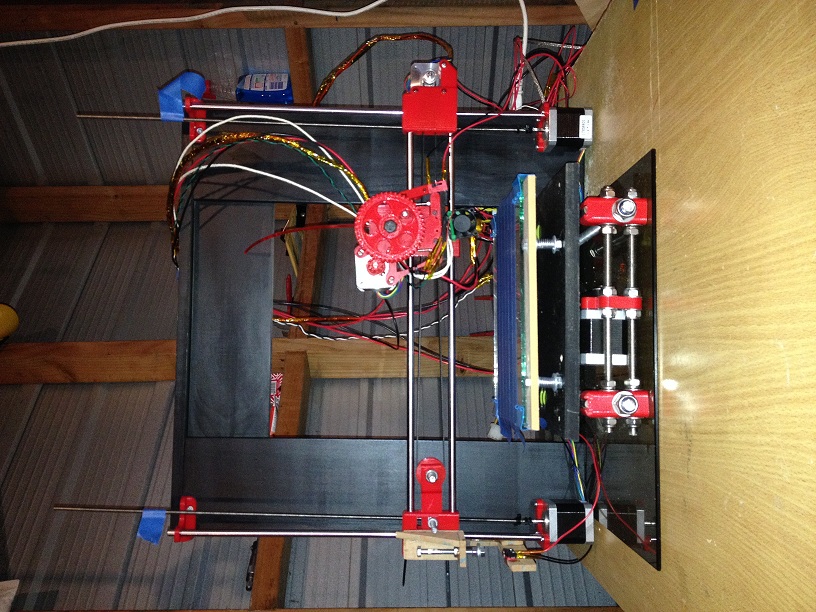
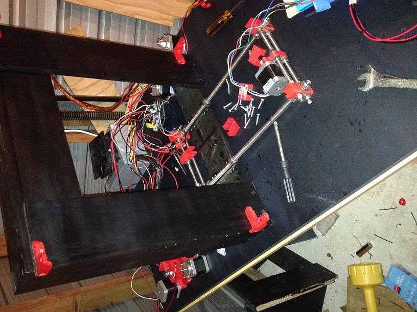
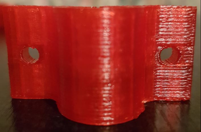
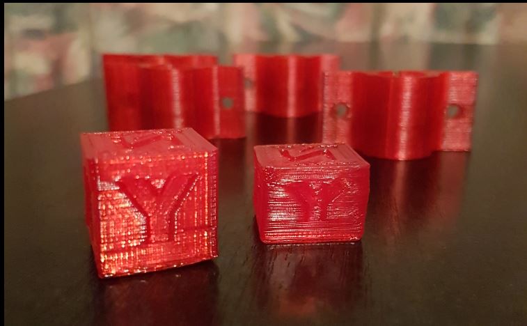
Sorry, only registered users may post in this forum.