Home
>
Reprappers
>
Topic
Marlin ramps 1.4 #define motherboard
Posted by marcocha
|
Marlin ramps 1.4 #define motherboard May 16, 2018 11:32AM |
Registered: 5 years ago Posts: 6 |
Hi everybody,
i'm trying to build my own 3d printer core xy style using ramps 1.4. I downloaded marlin 1.0.2 from the official site and i'm using arduino ide 1.8.5 to compile it. I found an online guide explaining how to install it, but i have a doubt: when i tell arduino which board i'm using in configuration.h ( through #define MOTHERBOARD_ ) i have to pick one from boards.h, right? I looked for ramps and i got :
define BOARD_RAMPS_13_EFB 33 // RAMPS 1.3 / 1.4 (Power outputs: Extruder, Fan, Bed)
#define BOARD_RAMPS_13_EEB 34 // RAMPS 1.3 / 1.4 (Power outputs: Extruder0, Extruder1, Bed)
#define BOARD_RAMPS_13_EFF 35 // RAMPS 1.3 / 1.4 (Power outputs: Extruder, Fan, Fan)
#define BOARD_RAMPS_13_EEF 36 // RAMPS 1.3 / 1.4 (Power outputs: Extruder0, Extruder1, Fan)
but i want to setup a two extruder printer with a bed made out of two heated beds, so i have two extruders, two beds and two fans. Do i have to consider the two beds as one using something like a mosfet?
Can i write at the end of the code something like EEBBFF or i have to try another way?
I didn't find anything online about this issue,
thank you in advance
|
Re: Marlin ramps 1.4 #define motherboard May 16, 2018 12:17PM |
Registered: 9 years ago Posts: 465 |
Well, a RAMPS board only has 3 power MOSFETs, which can be used for an extruder, a heat bed, or a PWM fan.
If you want 2 heat beds (Um... Why? Larger print area?) then you're going to have to take care of one of them a different way, or thermally couple the two together so that they affect each other's temperatures, or else you're going to have to do some custom hacking with another output and an external MOSFET. The nature of your question makes me think that this is probably not something that you have the skills for.
Solution #1. Get a bigger heat bed. If you are using 2 to extend your build volume, maybe just build a heat bed that is larger to begin with. Heater cartridges and an aluminum plate, then series/parallel your thermistors together to get an average temperature. Probably easier all around.
Solution #2: Use board 34, and set up an external bed controller, which you will probably have to manually adjust. This requires the least in software and hardware modification to a standard RAMPS board and the software. You can possibly slave the power for the second heat bed with a little thermal sensor project (ie, heat bed #2 gets powered on when the temp of heat bed #1 is above 35 deg C, and powered off when it drops below 30 deg C.) This will have some uneven heating when it cools, but at least you don't have to do everything manually. Might be a problem if you are using it to extend your build area, and have one sheet of glass covering both heat beds. Thermal stress is a bitch.
Solution #3. Redefine the RAMPS board to add one more thermistor/MOSFET set. you'll need another analogue converted pin for the thermistor. I know that there are more analogue pins on the Mega2560 than the three used, but I don't know if they're in use elsewhere. You'll have to modify the source code for Marlin to make a new board definition adding a TEMP_4_PIN definition, as well as a HEAT_4_PIN to control the external MOSFET. These will have to be connected to one of the AUX connectors on the RAMPS shield, assuming that one of them connects to an analogue pin. I haven't needed to do this, so I haven't looked for this in the aux pinouts. (I did look at some of the digital options available as input/output through the aux connectors.) This will require a programming ability to add in the extra pins, enable software control and monitoring for them with any LCD/controller that you may choose to use, as well as making that control available via gcode if you wish to be able to independently control the both. (I'm a programmer by trade, and I find the idea daunting.)
Honestly, I think that solution #1 is your cheapest, best bet.
|
Re: Marlin ramps 1.4 #define motherboard May 16, 2018 01:37PM |
Registered: 6 years ago Posts: 1,863 |
Quote
marcocha
I downloaded marlin 1.0.2 from the official site and i'm using arduino ide 1.8.5 to compile it.
You may need to use an older version than Arduino IDE 1.8.5 to compile. As they changed the syntax I used Arduino IDE 1.0.5 to compile older Marlin versions.
Presently using Marlin 1.1.5 and Arduino IDE 1.8.4 to compile Newer Marlin firmware.
|
Re: Marlin ramps 1.4 #define motherboard May 18, 2018 09:48AM |
Registered: 5 years ago Posts: 6 |
|
Re: Marlin ramps 1.4 #define motherboard May 18, 2018 09:55AM |
Registered: 6 years ago Posts: 1,863 |
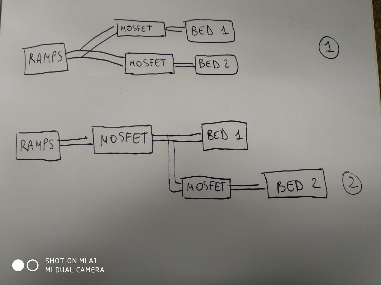
Use Diagram 1
Actually depending on you current draw you may only need a 40amp SSR.
Edited 1 time(s). Last edit at 05/18/2018 09:57AM by Roberts_Clif.
Actually depending on you current draw you may only need a 40amp SSR.

Edited 1 time(s). Last edit at 05/18/2018 09:57AM by Roberts_Clif.
|
Re: Marlin ramps 1.4 #define motherboard May 18, 2018 10:03AM |
Registered: 5 years ago Posts: 6 |
|
Re: Marlin ramps 1.4 #define motherboard May 18, 2018 10:32AM |
Registered: 6 years ago Posts: 1,863 |
Sorry, only registered users may post in this forum.