Home
>
Reprappers
>
Topic
Auto bed leveling over correcting?
Posted by peonking
|
Auto bed leveling over correcting? January 27, 2016 11:22AM |
Registered: 8 years ago Posts: 13 |
Hi
I got the auto bed leveling working mechanically with Marlin on Mendel max with Gen7. It uses a mechanical endstop.
Its able to perform G29 and produce a correctional matrix. Topology map also shows my left side of the bed is higher than the right side. When i set the nozzle to Z=0 using G1, it will almost flush against the right side of bed. While moving the nozzle to the left side, nozzle is moving up along the z axis slightly. However, gap between the nozzle and the bed gets larger too.
I've tried 2 points grid up to 4 points grid and they yield the same results.
Here is the result of G29 V4
Eqn coefficients: a: -0.00134520 b: -0.00004551 d: 20.06528472
Mean of sampled points: 19.93807411
planeNormal x: 0.001345 y: 0.000046 z: 1.000000
Bed Height Topography:
+-----------+
|...Back....|
|Left..Right|
|...Front...|
+-----------+
+0.10193 -0.01074 -0.15207
+0.11593 +0.04793 -0.07074
+0.05793 +0.01659 -0.10674
Corrected Bed Height vs. Bed Topology:
+0.05356 +0.04178 +0.00134
+0.06278 +0.09567 +0.07789
+0.00000 +0.05956 +0.03711
Bed Level Correction Matrix:
+0.999999 +0.000000 -0.001345
-0.000000 +1.000000 -0.000046
+0.001345 +0.000046 +0.999999
I'm speculating that its over correcting? I'm not sure. I've never used ABL before.
I've tried probing the points manually as follow. But the firmware doesn't seem to use these new values for leveling compensation. After the probes, Z axis doesn't move at all when I move the nozzle in the x directions. What did I do wrong?
>>> G30 p0
SENDING:G30 P0
Bed X: 180.00 Y: 270.00 Z: 21.84
>>> G30 p1
SENDING:G30 P1
Bed X: 0.00 Y: 270.00 Z: 22.80
>>> G30 p2
SENDING:G30 P2
Bed X: 0.00 Y: 100.00 Z: 22.81
>>> G30 p3 S
SENDING:G30 P3 S
Bed X: 180.00 Y: 100.00 Z: 21.99
Thanks
Calvin
Edited 1 time(s). Last edit at 01/28/2016 12:20AM by peonking.
|
Re: Auto bed leveling over correcting? January 27, 2016 08:12PM |
Registered: 8 years ago Posts: 13 |
Hi,
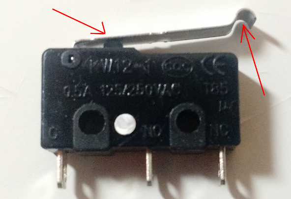
I just realized a possible cause. When you configure the probe to extruder offset, do u measure from nozzle to the metal tip of the switch or the actual switch button. ( see picture)
The difference in offset is quite huge. How much does this difference in offsets matter to the correctional matrix?
Which one do you guys measure?
Thanks
Calvin
|
Re: Auto bed leveling over correcting? January 27, 2016 10:56PM |
Registered: 8 years ago Posts: 13 |
|
Re: Auto bed leveling over correcting? January 28, 2016 09:02AM |
Registered: 8 years ago Posts: 3,525 |
The limitations of ABL as most of us use it are many, some of the inherent problems are the offset itself, the larger it is the less valid the ABL correction as you are not probing where the nozzle will actually be positioned during printing. In theory you can still calculate and apply a correction plane, but this assumes your print bed is flat. Invariably they are not at the 0.1mm accuracy level we are working around.
If the firmware applied a correction matrix to the coordinates by dividing the bed into squares and applying the corrections for each bed region to the printing coordinates which fall within it then this might be a better solution. As far as I am aware regular Marlin might use a 9 point grid etc... but it still only applies a correction plane to the whole bed, which if it is uneven will be incorrect in places. Rich Cattel's marlin for deltas does correct by bed region, but it cannot be used on cartesian printers, though the code might able to be ported into a fork of Marlin.
If you can relocate your probe so that it is as close to the nozzle as possible (z offset is unimportant as long as you can determine it) then you will improve the accuracy of this process. Better yet would be to use the nozzle itself as the probe, as you do when using force sensing resistors on a delta. Whilst this method is not perfect you do get a z min trigger when the nozzle touches the bed, at the x,y coordinate where the nozzle is located, i.e. useful accurate data about bed height at a given x,y coordinate.
You can also do this with a metal bed (making sure your nozzle is clean first) and then passing an electrical signal through it to the bed.
I have been thinking of designing a hinged x-carriage for my i3 which will effectively click a microswitch when the nozzle is pressed down onto the bed but haven't got that far with it yet. I have also got a hot end from China which an FSR built in for the same purpose.
You can test your probe repeatability using M48 you're looking for the smallest standard deviation you can get. [reprap.org]
Edited 1 time(s). Last edit at 01/28/2016 09:27AM by DjDemonD.
|
Re: Auto bed leveling over correcting? January 28, 2016 11:43AM |
Registered: 8 years ago Posts: 13 |
As far as i know, Grid method only creates a planar correctional matrix. Marlin has a mesh bed leveling feature that deals with unflat bed, but my hardware isn't setup for it. I just spent so much time "upgrading" to support servo and ABL, I'm trying to avoid more changes to the hardware.
Here is my current updated offsets:
#define X_PROBE_OFFSET_FROM_EXTRUDER 5 // Z probe to nozzle X offset: -left +right
#define Y_PROBE_OFFSET_FROM_EXTRUDER -63 // Z probe to nozzle Y offset: -front +behind
#define Z_PROBE_OFFSET_FROM_EXTRUDER -19.9 // Z probe to nozzle Z offset: -below (always!)
X is very close to the nozzle, though Y is very far away. The bed is not completely flat, but i think its within the 0.1mm range.
Since I'm having problem with the "X" direction, its safe to say my problem does not stem from offsets??
Here is the repeatability test at the last spot of abl probes.
>>> M48
SENDING:M48
M48 Z-Probe Repeatability test
Mean: 19.961666
Standard Deviation: 0.019730
>>> G29 n5 V4 T
SENDING:G29 N5 V4 T
G29 Auto Bed Leveling
Bed X: 15.000 Y: 30.000 Z: 19.825
Bed X: 52.000 Y: 30.000 Z: 19.868
Bed X: 89.000 Y: 30.000 Z: 19.881
Bed X: 126.000 Y: 30.000 Z: 19.858
Bed X: 163.000 Y: 30.000 Z: 19.806
Bed X: 163.000 Y: 82.000 Z: 19.835
Bed X: 126.000 Y: 82.000 Z: 19.934
Bed X: 89.000 Y: 82.000 Z: 19.916
Bed X: 52.000 Y: 82.000 Z: 19.918
Bed X: 15.000 Y: 82.000 Z: 19.873
Bed X: 15.000 Y: 134.000 Z: 19.900
Bed X: 52.000 Y: 134.000 Z: 19.899
Bed X: 89.000 Y: 134.000 Z: 19.914
Bed X: 126.000 Y: 134.000 Z: 19.913
Bed X: 163.000 Y: 134.000 Z: 19.857
Bed X: 163.000 Y: 186.000 Z: 19.857
Bed X: 126.000 Y: 186.000 Z: 19.940
Bed X: 89.000 Y: 186.000 Z: 19.937
Bed X: 52.000 Y: 186.000 Z: 19.947
Bed X: 15.000 Y: 186.000 Z: 19.895
Bed X: 15.000 Y: 238.000 Z: 19.911
Bed X: 52.000 Y: 238.000 Z: 19.915
Bed X: 89.000 Y: 238.000 Z: 19.905
Bed X: 126.000 Y: 238.000 Z: 19.903
Bed X: 163.000 Y: 238.000 Z: 19.851
Eqn coefficients: a: -0.00021261 b: 0.00022899 d: 19.87855720
Mean of sampled points: 19.89031982
planeNormal x: 0.000213 y: -0.000229 z: 1.000000
Bed Height Topography:
+-----------+
|...Back....|
|Left..Right|
|...Front...|
+-----------+
+0.02035 +0.02501 +0.01435 +0.01301 -0.03899
+0.00435 +0.05701 +0.04701 +0.04968 -0.03365
+0.00968 +0.00835 +0.02368 +0.02301 -0.03299
-0.01765 +0.02768 +0.02568 +0.04368 -0.05565
-0.06499 -0.02232 -0.00965 -0.03232 -0.08432
Corrected Bed Height vs. Bed Topology:
+0.03770 +0.05024 +0.04744 +0.05397 +0.00984
+0.03361 +0.09414 +0.09201 +0.10254 +0.02708
+0.05085 +0.05738 +0.08059 +0.08779 +0.03965
+0.03543 +0.08862 +0.09449 +0.12036 +0.02889
+0.00000 +0.05054 +0.07107 +0.05627 +0.01213
Bed Level Correction Matrix:
+1.000000 +0.000000 -0.000213
+0.000000 +1.000000 +0.000229
+0.000213 -0.000229 +1.000000
|
Re: Auto bed leveling over correcting? January 28, 2016 04:01PM |
Registered: 8 years ago Posts: 3,525 |
Whilst I won't say I can make sense out of all your numbers, what makes you say you're not having problems in the x direction?
The issue could simply be you're probing 63mm away from the nozzle in the y dimension.
Could you send your print head to a coordinate measure it's height manually using the nozzle then position the probe at the same spot and probe it. Do the same for another arbitrary point. See if there is any discrepancy between the z heights measured at each point by each method. If there is none then at least you've validated your probe. Therefore the offset and uneven bed is lost likely to blame.
Edited 2 time(s). Last edit at 01/28/2016 04:02PM by DjDemonD.
Sorry, only registered users may post in this forum.