Home
>
Reprappers
>
Topic
Heat bed MOSFET (not FUSE) overheating after auto tune command
Posted by ame
|
Heat bed MOSFET (not FUSE) overheating after auto tune command June 13, 2015 05:51PM |
Registered: 8 years ago Posts: 16 |
Hi all,
I am new to 3D printing and just finished my first purse i3 build, please point me in the right direction if this question has been answered already once.
I calibrated my stepper motors and extruder temperature and everything worked like a charm When I issued the auto tune command 'M303 E-1 C8 S90' to get the values for the heat bed a red LED turned on and the heat bed FUSE started to smoke
  I hit the emergency stop in repetier host and switch off the power supply.
The problem:
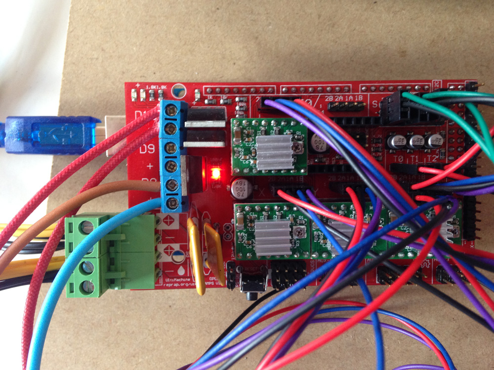
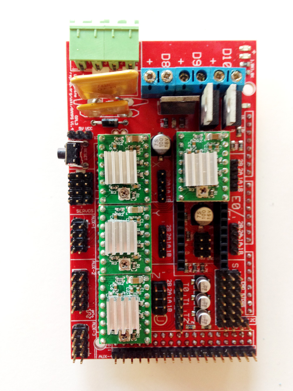
Each time I switch on the board the red LED is on and the FUSE gets hot within seconds and starts to smoke. I tried to resend the command as it seemed the RAMPS are stuck in some sort of loop but it did not help. I also tried to reset without success. If I disconnect the power for the heated bed 12V everything works, I can move the motors etc. but in the moment I connect the power again it is overheating (image attached).
I really don't know what to do anymore, because before running this command I could heat the bed manually and everything worked fine. Can I reset the hardware somehow?
Thank you for your help and please tell me if you need any additional information.
My Setup:
Arduino IDE 1.6.3
Latest Marlin download
RAMPS 1.4
OSX 10.10.3
Repetier-Host Mac 0.56
EDIT:
updated the title to change FUSE -> MOSFET. Thanks you Tim and Olaf
Edited 2 time(s). Last edit at 06/15/2015 06:27AM by ame.
I am new to 3D printing and just finished my first purse i3 build, please point me in the right direction if this question has been answered already once.
I calibrated my stepper motors and extruder temperature and everything worked like a charm
When I issued the auto tune command 'M303 E-1 C8 S90' to get the values for the heat bed a red LED turned on and the heat bed FUSE started to smoke I hit the emergency stop in repetier host and switch off the power supply. The problem:
Each time I switch on the board the red LED is on and the FUSE gets hot within seconds and starts to smoke. I tried to resend the command as it seemed the RAMPS are stuck in some sort of loop but it did not help. I also tried to reset without success. If I disconnect the power for the heated bed 12V everything works, I can move the motors etc. but in the moment I connect the power again it is overheating (image attached).
I really don't know what to do anymore, because before running this command I could heat the bed manually and everything worked fine. Can I reset the hardware somehow?
Thank you for your help and please tell me if you need any additional information.
My Setup:
Arduino IDE 1.6.3
Latest Marlin download
RAMPS 1.4
OSX 10.10.3
Repetier-Host Mac 0.56
EDIT:
updated the title to change FUSE -> MOSFET. Thanks you Tim and Olaf
Edited 2 time(s). Last edit at 06/15/2015 06:27AM by ame.
|
Re: Heat bed FUSE overheating after auto tune command June 13, 2015 06:20PM |
Registered: 10 years ago Posts: 14,672 |
Are you certain that you are powering the RAMPS from 12V and not more? Even if you have a short across the heated bed terminals, at 12V input the fuse should not be smoking.
Large delta printer [miscsolutions.wordpress.com], E3D tool changer, Robotdigg SCARA printer, Crane Quad and Ormerod
Disclosure: I design Duet electronics and work on RepRapFirmware, [duet3d.com].
Large delta printer [miscsolutions.wordpress.com], E3D tool changer, Robotdigg SCARA printer, Crane Quad and Ormerod
Disclosure: I design Duet electronics and work on RepRapFirmware, [duet3d.com].
|
Re: Heat bed FUSE overheating after auto tune command June 14, 2015 03:08PM |
Registered: 8 years ago Posts: 16 |
|
Re: Heat bed FUSE overheating after auto tune command June 14, 2015 04:15PM |
Registered: 10 years ago Posts: 14,672 |
You may have a short in your heat bed wiring, although even then the fuse shouldn't smoke, although it will certainly get hot. Perhaps they fitted the wrong type of fuse to your electronics board.
Large delta printer [miscsolutions.wordpress.com], E3D tool changer, Robotdigg SCARA printer, Crane Quad and Ormerod
Disclosure: I design Duet electronics and work on RepRapFirmware, [duet3d.com].
Large delta printer [miscsolutions.wordpress.com], E3D tool changer, Robotdigg SCARA printer, Crane Quad and Ormerod
Disclosure: I design Duet electronics and work on RepRapFirmware, [duet3d.com].
|
Re: Heat bed FUSE overheating after auto tune command June 14, 2015 05:28PM |
Registered: 8 years ago Posts: 16 |
|
Re: Heat bed FUSE overheating after auto tune command June 14, 2015 05:34PM |
Registered: 9 years ago Posts: 606 |
Auto tune changes absolutely nothing with regard to how much current your heater pulls, it just tunes the firmware to the thetmal 'mass' of the bed so it can better regulate the temp. An overcurrent problem is pretty much owned by hardware. To that end, what voltage do you see at either the heated bed itsrlf, or RAMPS output terminals when this happens? It sounds to me like you have a short circuit where you resoldered the bed connections.
- Tim
- Tim
|
Re: Heat bed FUSE overheating after auto tune command June 14, 2015 05:50PM |
Registered: 8 years ago Posts: 16 |
Thank you Tim,
I measured 0.56V on the heat bed which is strange, right?
I just removed all the connection (motors, sensors, heat bed, extruder...) and just connected the power supply for the heat bed and the red light went ON again. So this means there is a short circuit on the RAMPs board? Is there a way to find where the short circuit is and fix it?
Sorry for all my questions and thank you for you help!
Andreas
EDIT:
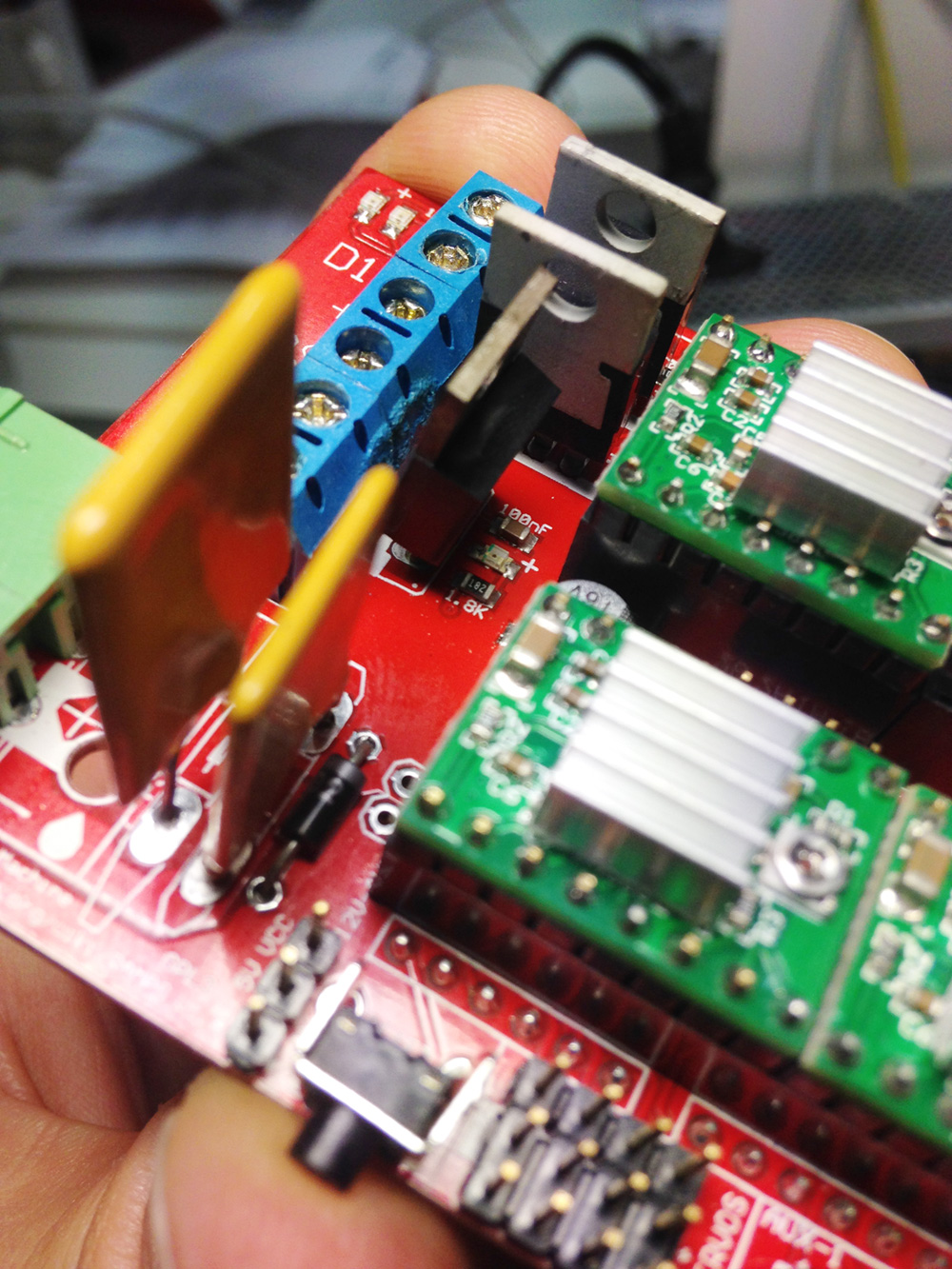
I think what smoked was the plastic of the D8 / D9 connectors because the FUSE was touching it (img attached).
Edited 1 time(s). Last edit at 06/14/2015 06:09PM by ame.
I measured 0.56V on the heat bed which is strange, right?
I just removed all the connection (motors, sensors, heat bed, extruder...) and just connected the power supply for the heat bed and the red light went ON again. So this means there is a short circuit on the RAMPs board? Is there a way to find where the short circuit is and fix it?
Sorry for all my questions and thank you for you help!
Andreas
EDIT:
I think what smoked was the plastic of the D8 / D9 connectors because the FUSE was touching it (img attached).
Edited 1 time(s). Last edit at 06/14/2015 06:09PM by ame.
|
Re: Heat bed FUSE overheating after auto tune command June 14, 2015 07:59PM |
Registered: 9 years ago Posts: 606 |
The red light means that the output is on - period. It in no way indicates a problem.
.56 volts at the heated bed indicates a *huge* problem, however! Something is shorted, thus pulling excess current, and causing the fuse to overheat. If you disconnect the heat bed, do you see voltage on the output terminals on the RAMPS, and does the problem go away? And what resistance do you measure across the heated bed leads while disconnected?
Oh, and looking at your picture, that's not a fuse - the fuses are the two yellow squarish parts closer to the board edge. The item melting the terminals is the MOSFET that controls the heater, and again, this is consistent with a short . . .
- Tim
Edited 1 time(s). Last edit at 06/15/2015 01:16PM by tadawson.
|
Re: Heat bed FUSE overheating after auto tune command June 15, 2015 02:33AM |
Registered: 8 years ago Posts: 5,232 |
It´s not the fuse, that gets hot! It´s a MOSFet...
Most likely it is a cheap one and the overcurrent issue has either killed it to be permanently on or the board has it´s own problem.
If you have solder skills you can replace it. But a Close inspection of both boards is recommendet.
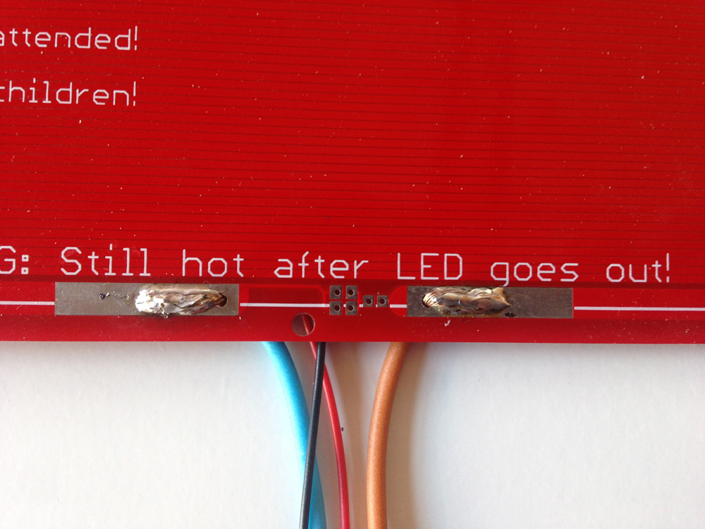
Please show us a picture of the heatbed solder Job, maybe there is a mistake.
-Olaf
Most likely it is a cheap one and the overcurrent issue has either killed it to be permanently on or the board has it´s own problem.
If you have solder skills you can replace it. But a Close inspection of both boards is recommendet.
Please show us a picture of the heatbed solder Job, maybe there is a mistake.
-Olaf
|
Re: Heat bed FUSE overheating after auto tune command June 15, 2015 11:33AM |
Registered: 10 years ago Posts: 477 |
The heatbed MOSFET overheating is a common problem with the China made RAMPS. Replace it with a IRLB8743 or IRLB8743PBF.
The old one can be hard to remove though.
Steve
My updated Instructable on our Prusa i3 Build
[www.instructables.com]
The old one can be hard to remove though.
Steve
My updated Instructable on our Prusa i3 Build
[www.instructables.com]
|
Re: Heat bed MOSFET (not FUSE) overheating after auto tune command June 15, 2015 12:57PM |
Registered: 8 years ago Posts: 16 |
Thank you all for your help and response!
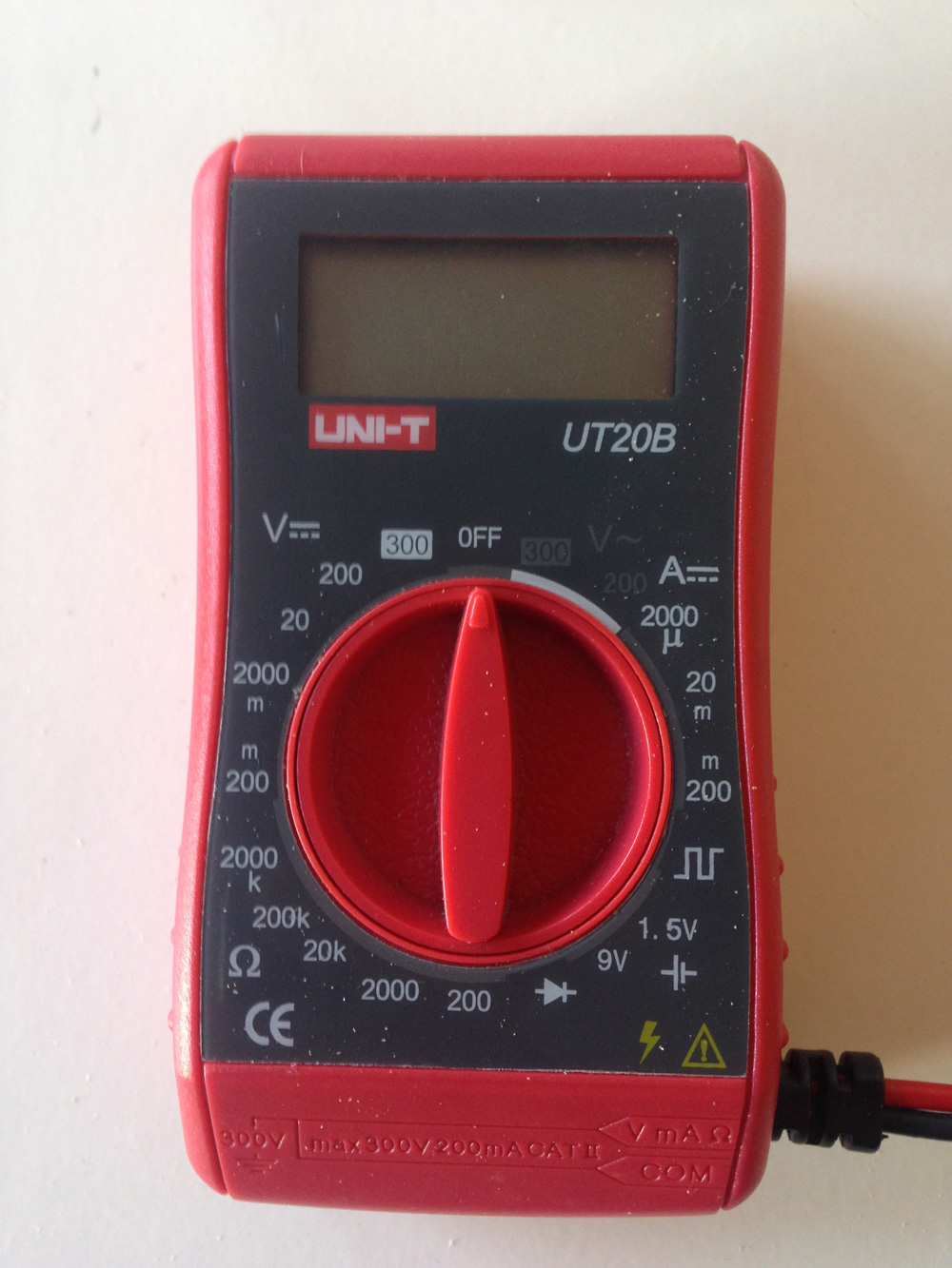
Tim: yes, disconnecting the heat bed resolves the overheating problem (the light is still on though). The voltage on the output terminals on the RAMPS without the heat bet reads 12.2V, so that is correct. I am sorry to ask this but I am very new to electronics, so I don't know how to measure the resistance, I attached an image of my multimeter if you could help me. And thank you for pointing out that it is the MOSFET
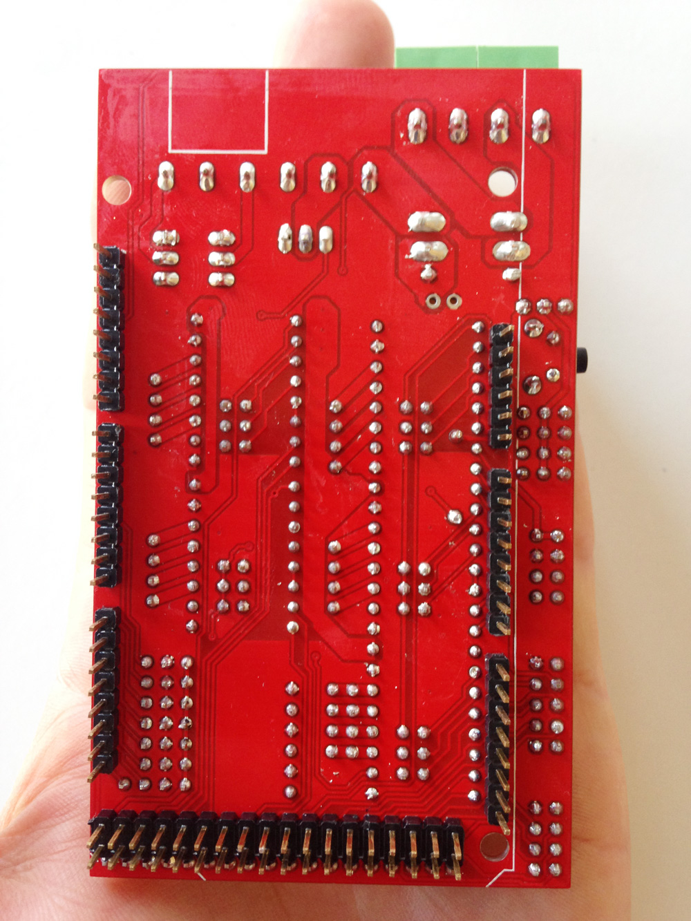
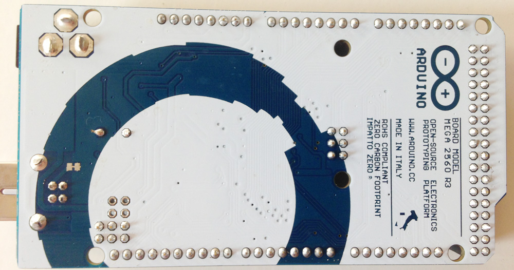
Olaf: I attached 2 images of the RAMPS board (top / bottom). I think the MOSFET is still intact as everything is fine if the heated bed is not connected. Attached also an image of my poor soldering job on the heat bed, can you spot any error?
Steve: this is the information printed on my MOSFET (image attached as well)
P55NF06L
7SABF V6
PHL 243
I am unsure if I am skilled enough to replace the MOSFET Do you have any recommendation as where to buy the MOSFET you recommended in Europe?
Tim: yes, disconnecting the heat bed resolves the overheating problem (the light is still on though). The voltage on the output terminals on the RAMPS without the heat bet reads 12.2V, so that is correct. I am sorry to ask this but I am very new to electronics, so I don't know how to measure the resistance, I attached an image of my multimeter if you could help me. And thank you for pointing out that it is the MOSFET
Olaf: I attached 2 images of the RAMPS board (top / bottom). I think the MOSFET is still intact as everything is fine if the heated bed is not connected. Attached also an image of my poor soldering job on the heat bed, can you spot any error?
Steve: this is the information printed on my MOSFET (image attached as well)
P55NF06L
7SABF V6
PHL 243
I am unsure if I am skilled enough to replace the MOSFET
Do you have any recommendation as where to buy the MOSFET you recommended in Europe?
|
Re: Heat bed FUSE overheating after auto tune command June 15, 2015 01:27PM |
Registered: 9 years ago Posts: 606 |
Resistance is indicated with the Omega symbol, and is the bottom left of the meter dial. For this, we are looking for low resistances, so select '200' (pointer straight down) and connect the meter leads to the heated bed leads, and tell us what you see.
The solder work looks decent from here, assuming that those are the correct pads.
It's also possible to get a strand or two of wire shorting at the connector on the RAMPS.
Once again, the red LED on the RAMPS simply means that it is turning the heater output on, and not seeing it would be a problem! Red on a RAMPS card does *NOT* indicate a problem . . . more like a heartbeat . . .
It may be a crap MOSFET, but unless it had a very odd failure, if you see power when the LED is on and the output, and none when it is off, then it has not failed outright. If you got a dud that eats 11.5 volts when on, that would be impressive!
To replace it, clip the old one off the board, apply as little heat as needed to get the remaining leads out, clean the holes with solder wick, a sucker, blowing hard, whatever. Insert the new part facing the same way as the old one, and solder, again, trying to use as little heat as needed to get a good joint to avoid damaging the board.
- Tim
Edited 2 time(s). Last edit at 06/15/2015 02:28PM by tadawson.
|
Re: Heat bed MOSFET (not FUSE) overheating after auto tune command June 15, 2015 02:25PM |
Registered: 10 years ago Posts: 477 |
What is the resistance of the heatbed? Should be around 1.3 Ohms
If you want a high quality RAMPS these are the guys to talk to:
[www.staticboards.es]
Steve
My updated Instructable on our Prusa i3 Build
[www.instructables.com]
If you want a high quality RAMPS these are the guys to talk to:
[www.staticboards.es]
Steve
My updated Instructable on our Prusa i3 Build
[www.instructables.com]
|
Re: Heat bed MOSFET (not FUSE) overheating after auto tune command June 16, 2015 03:46AM |
Registered: 8 years ago Posts: 5,232 |
Quote
tadawson
Once again, the red LED on the RAMPS simply means that it is turning the heater output on, and not seeing it would be a problem!
If you have a RAMPS board where the red LED is always ON, you have a problem! You should read more closely, before you give advice...
Soldering slow with low temp is not always the best idea. Especially with those huge solderpads for the MOSFETs you need higher temp or bigger solder-tip.
The solderjob on the heatbed was definitely a bit to cold.
While you are busy with the solder, you could check the endstop-connector on the bottom of the RAMPS. There were a few bad solderjoints and also some splattered solder everywhere. You should remove the splattered stuff and also check the top of the board for more. ( Those loose blobs can cause serious problems on any electronics )
-Olaf
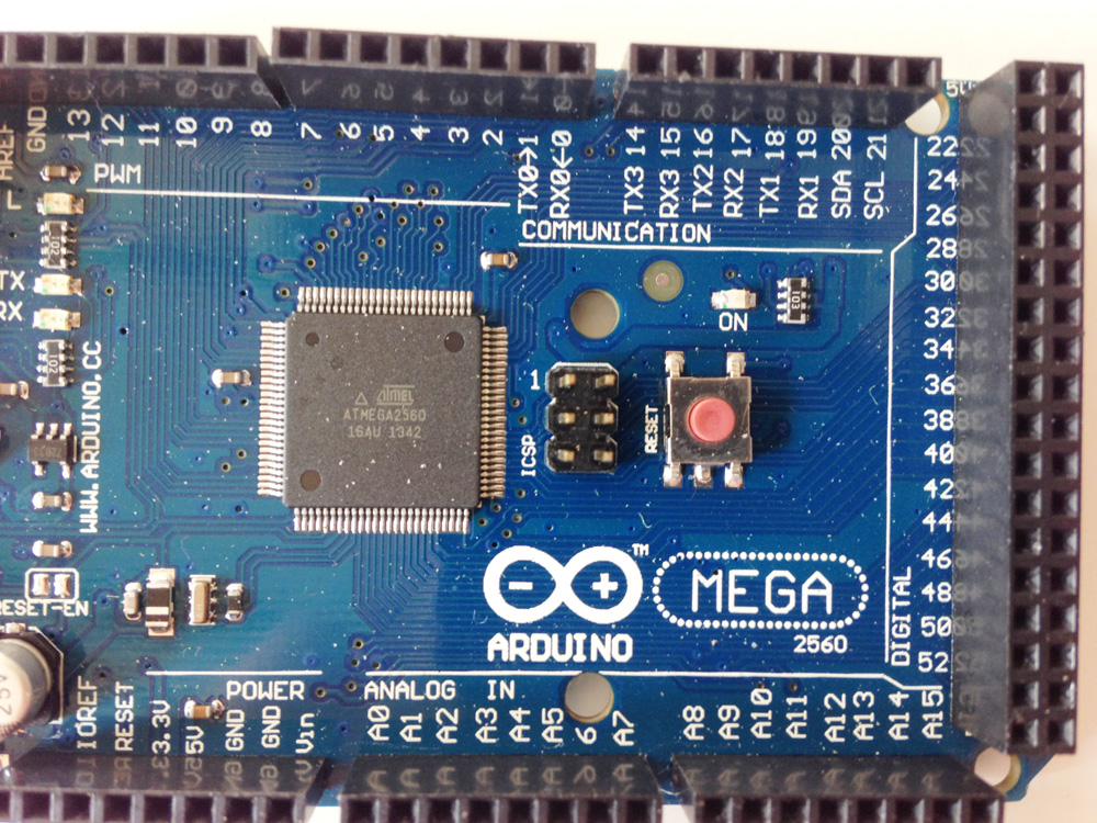
PS: We still haven´t found the reason, why the MOSFET is always on. Maybe the mega board is faulty. More pics from the megaboard ( closeup of the processor ) are welcome
|
Re: Heat bed MOSFET (not FUSE) overheating after auto tune command June 16, 2015 05:11AM |
Registered: 9 years ago Posts: 606 |
If he truly has a shorted bed, it likely overheated and failed.
And I was under the assumption that the LED was only on when autotune or heating was attempted . . . not always. In any case, the MOSFET should not smoke or get that hot if the heatbed is good, no matter how long it is on.
Simple test . . . separate the Arduino and the RAMPS . . . if it still comes on, the MOSFET is pretty much all it can be and should be replaced (and myself, if I overheated one that badly, I'd replace it anyhow, working or not . . .)
- Tim
|
Re: Heat bed MOSFET (not FUSE) overheating after auto tune command June 16, 2015 06:09AM |
Registered: 8 years ago Posts: 16 |
Thank you for the explanation on the resistance Tim
Soldering of the heat bed: what do you mean by correct pads? I just have these 2 pads on the bed so there is no other way I could connect the wires.
I see power of 12.16V when the LED is on and none when it's off so that should be right (no heat bed connected). Without the heat bed connected I can even touch the MOSFET and it does not get hot a at all.
The LED on the board is always ON regardless of heating the bed or not. It stayed ON forever after running the autotune command for the first time. The LED is also ON if the disconnected from the mega board.
I measured the resistance on D8 of the RAMPS board and it shows 1, I tried the same on the D10 and if I do another LED lights up and I measure 1 as well.
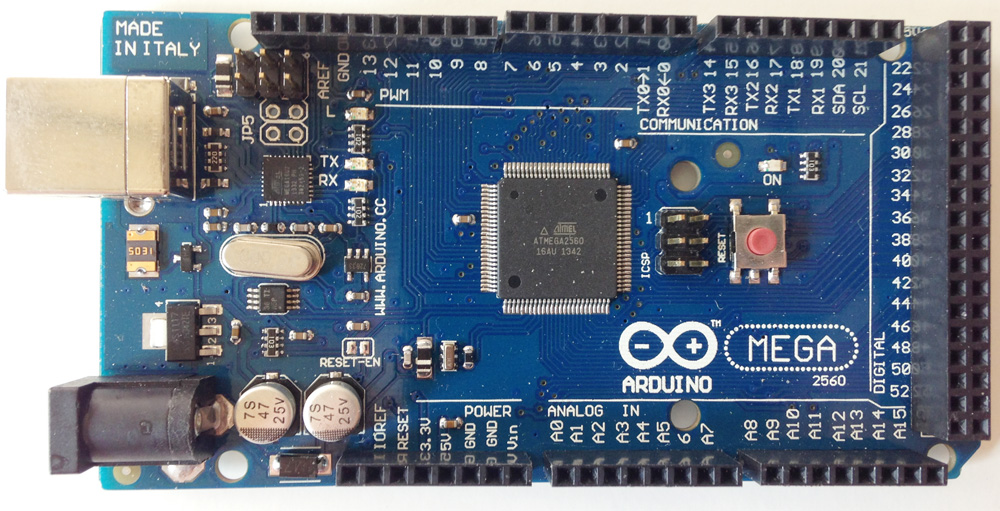
I did buy the RAMPS and mega board already completely soldered, so I did not touch it in any way. Attached a few images of the mega board.
Thank you guys once again for your help!
Andreas
Edited 1 time(s). Last edit at 06/16/2015 06:10AM by ame.
Soldering of the heat bed: what do you mean by correct pads? I just have these 2 pads on the bed so there is no other way I could connect the wires.
I see power of 12.16V when the LED is on and none when it's off so that should be right (no heat bed connected). Without the heat bed connected I can even touch the MOSFET and it does not get hot a at all.
The LED on the board is always ON regardless of heating the bed or not. It stayed ON forever after running the autotune command for the first time. The LED is also ON if the disconnected from the mega board.
I measured the resistance on D8 of the RAMPS board and it shows 1, I tried the same on the D10 and if I do another LED lights up and I measure 1 as well.
I did buy the RAMPS and mega board already completely soldered, so I did not touch it in any way. Attached a few images of the mega board.
Thank you guys once again for your help!
Andreas
Edited 1 time(s). Last edit at 06/16/2015 06:10AM by ame.
|
Re: Heat bed MOSFET (not FUSE) overheating after auto tune command June 16, 2015 03:13PM |
Registered: 9 years ago Posts: 606 |
You want to measure the resistance of the heated bed, not the RAMPS . . . put the probes on either the heatbed wires or solder pads (one probe to each). And I asked about the 'right pads' on the bed because the photo was so narrow, that it wasn't possible to see if those were the only ones or not.
And it sounds like the MOSFET has failed, and needs to be replaced. Whether the problem is a bad bed, a bad MOSFET, or a MOSFET failure due to a bad bed is what we need to determine. As others have mentioned, some of the el-cheapo Chinese RAMPS cards use the wrong MOSFETS that tend to run hot, and the PID autocal may just have put it over the edge. The good news is that the board will likely be fine if you get the right MOSFET on it. I just made an order, and goofed and got 2x what I needed and would send you one if you were in the US . . . but since the part was just $1.25 or so, it would not make sense internationally . . .
- Tim
Edited 2 time(s). Last edit at 06/16/2015 03:20PM by tadawson.
|
Re: Heat bed MOSFET (not FUSE) overheating after auto tune command June 17, 2015 02:16AM |
Registered: 8 years ago Posts: 59 |
So you measure 12.16V at the bed when it is on, and 0V when it is off?
That sounds fine. If the bed was shorted you would not get 12V across it.
The resistance of the bed would be useful to know, but it seems that your meter does not have the resolution to give an accurate reading (a few tips about measuring resistance: don't do it when there is power on the circuit - disconnect it from the RAMPS, and for low resistance readings, short the probes of your meter together after or before the reading so you know how much of the resistance is in the probes, subtract that from your circuit resistance measurement).
As already mentioned, the MOSFETs often used on the RAMPS boards are not the right ones. But you have the P55NF06L. That IS the correct one (mine came with a P55NF06.... no 'L', which makes a big difference). I would have thought your MOSFET would be ok.
I wonder if you really have a problem. Even the correct MOSFET will get a bit hot. In my case, the original (incorrect) MOSFET got to 185 degrees C pretty quickly. I changed it for a logic level MOSFET (not the STP55NF06L, but an equivalent) and it got to almost 60 degrees C. When you touch it, it will feel hot, but it doesn't mean it has failed. When it was pressed against the terminal, it would have got hotter as the terminal would have acted a bit like an insulator on that side and the MOSFET would not have been able to cool as effectively, so maybe it was able to get hot enough to melt the terminal and create a bit of smoke.
However, I do wonder why it always turns on when you power up the electronics. Are you able, through the display or with the slicer, to set the bed temperature to something low, five degrees or something? Just do a normal print (I have never 'tuned' my system so I don't know what that does in any detail). It should not come on if the setting is below the measured temperature (ahh.. is that your problem, is it measuring the temperature of the bed correctly?).
|
Re: Heat bed MOSFET (not FUSE) overheating after auto tune command June 17, 2015 02:42AM |
Registered: 10 years ago Posts: 14,672 |
I suggest you do two things:
1. Buy a couple of IRLB8743pbf or IRLB3034pbf mosfets and replace your heated bed mosfet with one of them.
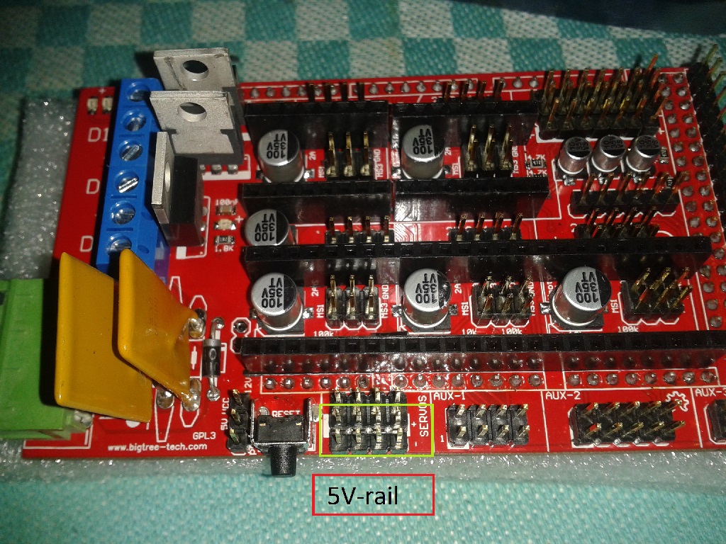
2. Measure the 5V rail on the RAMPS. If it is below 4.8V then the voltage regulator on the Arduino has probably overheated. You may be drawing too much power drom the 5V rail.
Large delta printer [miscsolutions.wordpress.com], E3D tool changer, Robotdigg SCARA printer, Crane Quad and Ormerod
Disclosure: I design Duet electronics and work on RepRapFirmware, [duet3d.com].
1. Buy a couple of IRLB8743pbf or IRLB3034pbf mosfets and replace your heated bed mosfet with one of them.
2. Measure the 5V rail on the RAMPS. If it is below 4.8V then the voltage regulator on the Arduino has probably overheated. You may be drawing too much power drom the 5V rail.
Large delta printer [miscsolutions.wordpress.com], E3D tool changer, Robotdigg SCARA printer, Crane Quad and Ormerod
Disclosure: I design Duet electronics and work on RepRapFirmware, [duet3d.com].
|
Re: Heat bed MOSFET (not FUSE) overheating after auto tune command June 17, 2015 04:16AM |
Registered: 8 years ago Posts: 5,232 |
Is it possible, that the board is still in autotune mode? Thát would explain the permanently lit red LED...
It takes a long time before it is done and with the holy smoke rising, he sure cut off the power.
Is the M303 E-1 C8 S90 command stored in EEprom until it´s done?
Wouldn´t it be better to use S70? Some beds don´t make it to 90°C at all without the right tricks at hand.
-Olaf
It takes a long time before it is done and with the holy smoke rising, he sure cut off the power.
Is the M303 E-1 C8 S90 command stored in EEprom until it´s done?
Wouldn´t it be better to use S70? Some beds don´t make it to 90°C at all without the right tricks at hand.
-Olaf
|
Re: Heat bed MOSFET (not FUSE) overheating after auto tune command June 17, 2015 03:07PM |
Registered: 8 years ago Posts: 16 |
blabbersnitch:
Thank you for the information about how to measure the resistance
I measure a constant 0.3 Ohms when I short the probes together. Now, without power on the RAMPS I measure 1.2-1.1 Ohms on the heat bed.
I connected the heat bed again and powered up everything and measure 9.3V on the heat bed. After mounting the RAMPS board on the Arduino I tried to connect to set the temperature manually to 5°C but could not do it. The heat bed was heating up with the red LED ON. I tried to connect / disconnect several times and managed after switching off the power but got this error:
19:29:47: Error rinter stopped due to errors. Fix the error and use M999 to restart. (Temperature is reset. Set it after restarting)
Olaf: this was my thought too, as I powered off the printer before autotune command was complete I thought it might still be stored somewhere and run every time.
My next steps now are:
1. connect all the cables to the RAMPS board
2. connect to the printer
3. turn on the power
4. send the M999 command
5. Try to set the temperate of the board to 5°C
Thank you for the information about how to measure the resistance
I measure a constant 0.3 Ohms when I short the probes together. Now, without power on the RAMPS I measure 1.2-1.1 Ohms on the heat bed.
I connected the heat bed again and powered up everything and measure 9.3V on the heat bed. After mounting the RAMPS board on the Arduino I tried to connect to set the temperature manually to 5°C but could not do it. The heat bed was heating up with the red LED ON. I tried to connect / disconnect several times and managed after switching off the power but got this error:
19:29:47: Error
rinter stopped due to errors. Fix the error and use M999 to restart. (Temperature is reset. Set it after restarting)Olaf: this was my thought too, as I powered off the printer before autotune command was complete I thought it might still be stored somewhere and run every time.
My next steps now are:
1. connect all the cables to the RAMPS board
2. connect to the printer
3. turn on the power
4. send the M999 command
5. Try to set the temperate of the board to 5°C
|
Re: Heat bed MOSFET (not FUSE) overheating after auto tune command June 18, 2015 05:00AM |
Registered: 8 years ago Posts: 5,232 |
9.3V sounds better, but still a big powerloss somewhere.
Like dc42 wrote, measure the 5V rail, if this is too low, the FETs won´t switch on completely and suffer under huge losses/heat. #see picture
Pull off all the endstops , drivers and LCD to see if anything is asking to much power from the 5V regulator.
-Olaf
Like dc42 wrote, measure the 5V rail, if this is too low, the FETs won´t switch on completely and suffer under huge losses/heat. #see picture
Pull off all the endstops , drivers and LCD to see if anything is asking to much power from the 5V regulator.
-Olaf
|
Re: Heat bed MOSFET (not FUSE) overheating after auto tune command June 22, 2015 03:25PM |
Registered: 8 years ago Posts: 16 |
 I tried it several times and tried any combination of the 3 pins. What does this mean?
|
Re: Heat bed MOSFET (not FUSE) overheating after auto tune command June 22, 2015 04:43PM |
Registered: 9 years ago Posts: 606 |
|
Re: Heat bed MOSFET (not FUSE) overheating after auto tune command June 22, 2015 05:12PM |
Registered: 8 years ago Posts: 16 |
|
Re: Heat bed MOSFET (not FUSE) overheating after auto tune command June 22, 2015 08:50PM |
Registered: 8 years ago Posts: 59 |
Quote
ame
The LED is also ON if the disconnected from the mega board.
Andreas
I was just looking through the thread again and saw this. The following post had Tim suggesting changing the MOSFET. I think I have to agree.
How can the MOSFET turn on if the Arduino is not there to pull up the gate? It looks like the MOSFET has failed. I guess other possibilities is a dag or some other rubbish on the board pulling the gate up to 5V (or 12V... or something), or a dag or some other rubbish pulling the drain down to ground. I think a failed MOSFET is more likely. You could check the gate voltage to confirm.
Eric
|
Re: Heat bed MOSFET (not FUSE) overheating after auto tune command June 25, 2015 07:40AM |
Registered: 8 years ago Posts: 16 |
Tim:
- I measured the end stops and get constant 5V on all of them
- Where can I set this jumper to enable the 5V rail?
Eric:
- How do I measure the gate voltage?
To summarise:
a) If I have RAMPS board and Arduino connected and all the other cables unplugged:
- red light ON
- 12.2V on both power inputs coming from the ATX power supply
- 12.2V voltage on D8
- 5V on all end stops
- I can touch the MOSFET it does not get warm
b) RAMPS and Arduino connected and all the cables plugged in (heat bed, stepper motors, end stops, extruder, heat sensors, etc.)
- red light ON
- immediate heating of the bed
- 12.2V on both power inputs coming from the ATX power supply
- 9.6V voltage on D8
- 9.6 / 9.5V on heat bed
- 5V on end stops
Just to confirm, the thermistors seem to work fine as I get either room temperature or if I set the extruder to 40°C it heats up and stops once it reaches the temperature.
While writing this lines I tried to connect several times to the printer and got the following in my logs:
< 11:36:03: Errorrinter stopped due to errors. Fix the error and use M999 to restart. (Temperature is reset. Set it after restarting)
Running the M999 command does not work and the connection is closed and I got an error message from my computer that the USB is drawing too much power (image attached).
Interestingly I just switched OFF / ON the printer and the connection to the computer and the Red LED is OFF ? No heating of the bed, stable room temperate for both thermistors and no voltage output on D8. Maybe the M999 did resolve the problem??? Kind of confused right now....
Which other tests could I make to ensure that everything is OK now? I definitely should change the MOSFET, do you know of some good supplier in Europe?
Many thanks to all of you and sorry for all my questions and lack of knowledge - learning everyday with your help!
Andreas
EDIT: corrected some typos
Edited 3 time(s). Last edit at 06/25/2015 07:43AM by ame.
- I measured the end stops and get constant 5V on all of them
- Where can I set this jumper to enable the 5V rail?
Eric:
- How do I measure the gate voltage?
To summarise:
a) If I have RAMPS board and Arduino connected and all the other cables unplugged:
- red light ON
- 12.2V on both power inputs coming from the ATX power supply
- 12.2V voltage on D8
- 5V on all end stops
- I can touch the MOSFET it does not get warm
b) RAMPS and Arduino connected and all the cables plugged in (heat bed, stepper motors, end stops, extruder, heat sensors, etc.)
- red light ON
- immediate heating of the bed
- 12.2V on both power inputs coming from the ATX power supply
- 9.6V voltage on D8
- 9.6 / 9.5V on heat bed
- 5V on end stops
Just to confirm, the thermistors seem to work fine as I get either room temperature or if I set the extruder to 40°C it heats up and stops once it reaches the temperature.
While writing this lines I tried to connect several times to the printer and got the following in my logs:
< 11:36:03: Error
rinter stopped due to errors. Fix the error and use M999 to restart. (Temperature is reset. Set it after restarting)Running the M999 command does not work and the connection is closed and I got an error message from my computer that the USB is drawing too much power (image attached).
Interestingly I just switched OFF / ON the printer and the connection to the computer and the Red LED is OFF ? No heating of the bed, stable room temperate for both thermistors and no voltage output on D8. Maybe the M999 did resolve the problem??? Kind of confused right now....
Which other tests could I make to ensure that everything is OK now? I definitely should change the MOSFET, do you know of some good supplier in Europe?
Many thanks to all of you and sorry for all my questions and lack of knowledge - learning everyday with your help!
Andreas
EDIT: corrected some typos
Edited 3 time(s). Last edit at 06/25/2015 07:43AM by ame.
|
Re: Heat bed MOSFET (not FUSE) overheating after auto tune command June 25, 2015 09:36AM |
Registered: 8 years ago Posts: 59 |
Well,
You get this M999 error message, and then you get your strange USB power message too!
Something weird is going on here! (That's just in case you didn't know.)
But, on the matter of determining if the MOSFET is being commanded to come on when it shouldn't, or if it is coming on because it is faulty, you can check its gate voltage by measuring the voltage across its two outer pins. One is the gate and one is the source. The centre pin (and the tag) are the drain. We aren't interested in the drain.
If the MOSFET is being told to turn on, you will measure 5Vdc (or -5Vdc, depending which meter probe goes where) between gate and source (the outer MOSFET pins). If the MOSFET is not being told to turn on, then you will measure 0Vdc. If you measure 0Vdc and the MOSFET is on, I would be cutting it out and replacing it.
Getting the multimeter probes onto those pins/legs/solder pads is tricky (I just tried it, but I was able to do it). Ironically, having that red LED on all the time is good as it will help you see what you are doing! Maybe do a test run before applying power, you don't want to short anything with the meter probes.
If you replace the MOSFET, you have a few options. You need an n-channel (enhancement mode) MOSFET. You need one that will turn on with a low gate voltage (most turn on at voltages above 5V... the low gate voltage ones are sometimes called 'logic level' MOSFETSs), and you want one with low on-state resistance.. I used an FDP8896 (I already had some) and have been very happy with it. I have seen others nominating IRLB8743pbf and IRLB3034pbf (see dc42's post.. I just had a look at their datasheets and they look like even better options than my FDP8896!). In fact, I think the original specified STP55NF06L would also do ok (that's what you had, but as I found out it isn't what is always installed on the RAMPS boards... my board had the STP55NF06 without the 'L'... the 'L' was important as - I think - it indicates Logic Level). However, if you had to buy a new MOSFET, get one of the other ones.
Hmmm... I get a bit chatty after a few grappas.... My wife just told me someone was taking her clothes off on the TV... and I replied 'that's nice honey, but not as stimulating as talking electronics". Maybe I need to get some help.
I sometimes buy from RS components (sometimes I use element 14). You buy online. Huge range. Prices are ok. But you get overnight delivery (and that's here in Australia!... If we get overnight delivery here, then I am sure you will get it in Europe... Australia is big! My wife and I drove to a wedding a few years ago, and when the GPS said 'next left turn: 1200km' I took a photo!... actually, it was one km later). Google 'RS Components' and your country (I know they operate in the UK... and probably everywhere else!).
I would do the MOSFET test, then start thinking about replacing the entire RAMPS board....
One more grappa then off to bed ;-)
Good Luck
Eric
|
Re: Heat bed MOSFET (not FUSE) overheating after auto tune command June 25, 2015 11:49AM |
Registered: 9 years ago Posts: 606 |
If you see 5v on the endstop connectors, then the 5v supply is fine . . . there is only one. The jumper for the 5v rail to the servos is a 3 pin header, just to the left of the reset button, down near the servo connectors on the edge of the board (on some images I have found online, it seems that this header, as well as the servo pins sometimes are not populated . . . not sure what you have . . ). This won't isolate anything but the servos, so if you have not using a servo for an autolevel probe or some such, won't gain you anything.
M999 should be nothing more than a reset after a fault . . . the same thing as a power cycle. Nothing on the Arduino/RAMPS setup maintains any semblance of state, just the few settings that go into the prom . . . As a side note (and forgive me if this is redundant), but with the diode present on the RAMPS, the Arduino will take power from either the USB connection *OR* the RAMPS - to truly power cycle the card, you need to disconnect both at the same time.
Having said that, with the MOSFET now off, there is either 1) Some really bad voodoo going on on that card of 2) The damn thing finally got tired of being baked and failed outright . . . The trick is to see if you can ever get it to come back on again at this point.
Myself, I would have replaced the MOSFET a long, long, time ago . . . it's too cheap a part to spend this much time wondering about . . . about $1.25 in the US . . .
Myself, I would not even begin to think about replacing the RAMPS card for this . . . there are zero active components between the Mega and the MOSFET, so unless a trace is cut, there is nothing to fail beyond the FET. If you want to avoid replacing the part, then maybe a replacement would be in order, but from a troubleshooting point of view, it has very, very, little value . . . Kinda like buying a new car because the cigarette lighter is broken . . .
For suppliers, you ought to be able to do a search with the part number, and get hits on suppliers in your country. RS Components, Farnell, etc. I have heard of, and they sell components . . .
- Tim
Edited 1 time(s). Last edit at 06/25/2015 11:53AM by tadawson.
|
Re: Heat bed MOSFET (not FUSE) overheating after auto tune command June 25, 2015 04:03PM |
Registered: 8 years ago Posts: 16 |
Thank you Eric and Tim!
I measured the MOSFET gate voltage by measuring the outer pins. Without power I get 0V, with power 0.2V and the LED is flickering. I am certain the MOSFET has finally failed... I was hoping to avoid a soldering job on the RAMPS board as I don't consider myself a solder wizard
At least we found the problem (well, all of the posters suggested it since the beginning...) I will order a new piece and tell you when I successfully swapped it!
Thank you all once again, I hope I can get to print finally
I measured the MOSFET gate voltage by measuring the outer pins. Without power I get 0V, with power 0.2V and the LED is flickering. I am certain the MOSFET has finally failed... I was hoping to avoid a soldering job on the RAMPS board as I don't consider myself a solder wizard
At least we found the problem (well, all of the posters suggested it since the beginning...)
I will order a new piece and tell you when I successfully swapped it!Thank you all once again, I hope I can get to print finally

Sorry, only registered users may post in this forum.