New Printer Design
Posted by Speaker-2-Animals
|
New Printer Design February 28, 2018 12:16PM |
Registered: 6 years ago Posts: 6 |
Hi Everyone,
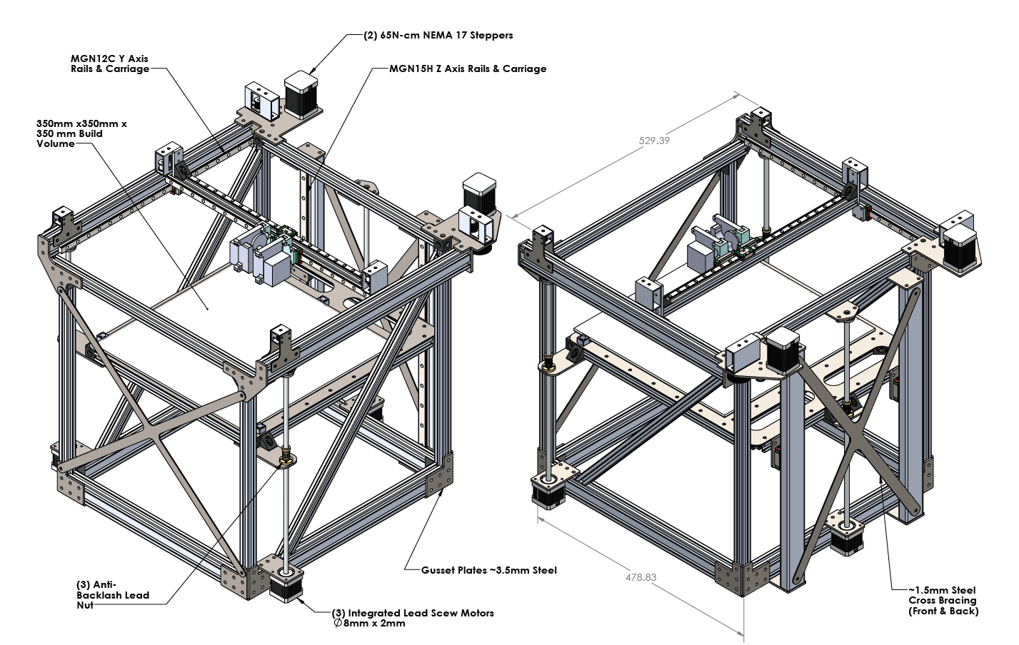
This is my design for a CoreXY machine. I'd like to print mechanical parts at high quality out of polycarbonate, delrin, abs and other "exotic" filaments. I've got a heated build chamber that it should fit inside. Travel moves of 200 mm/s, accelerations of 7500 mm/s^2 and print speeds up to 100mm/s would be my goal for speed. The math says this should be achievable but I'd be curious to hear what you all have to say. I've seen the parking extruders that use electromagnets to grab the carriages and I'd like to use something similar. The placement of the motors is a bit unconventional at the back but this because the heated chamber has room back there. Other design features are:
9mm kevlar core belts
DuetWifi Control Board
BLTouch Probe
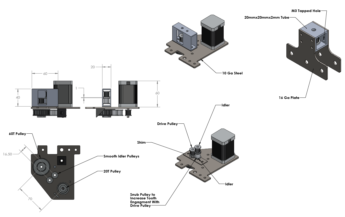
Drive steppers are 17HS24-2104S and geared down 3:1
My big burning questions right now are:
Are the MGN12C adequate for the Y axis rails or should I go with the H?
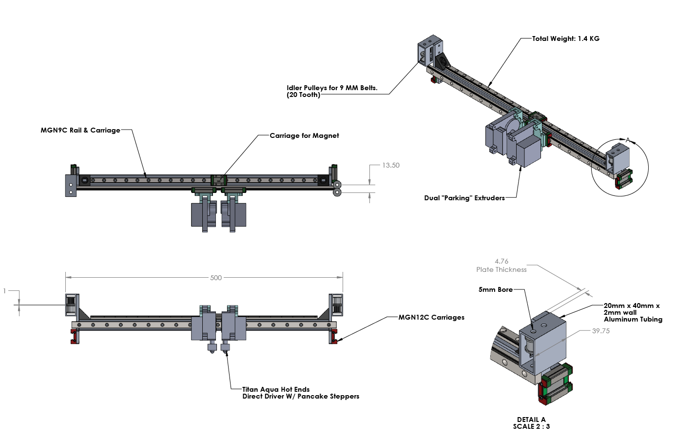
Are the MGN12H on the X axis where the extruders mount overkill? Could I go down to MGN9 and save ~200 grams? Is this axis too heavy anyways?
Is it a good idea to constrain the top of the Z lead screws?
Things I think may need work:
Belt tensioning could be done by sliding the front pulleys back but this isn't the best system.
I wish there was better tooth engagement on the drive pulley, there is a snub pulley but it is not optimally placed, I think it will get 5-7 teeth.
I need to add fastners to the model.
I need to design the extruder mounts and parking system but I'm pretty sure I could build the frame without having that done.
Adjusting the pulleys to keep the belts parallel will probably involve rebuilding certain parts so I'd like to improve that too.
I've got a machine shop and a CNC plasma cutter at my disposal so whatever you think might improve the design I can probably build.
This is my design for a CoreXY machine. I'd like to print mechanical parts at high quality out of polycarbonate, delrin, abs and other "exotic" filaments. I've got a heated build chamber that it should fit inside. Travel moves of 200 mm/s, accelerations of 7500 mm/s^2 and print speeds up to 100mm/s would be my goal for speed. The math says this should be achievable but I'd be curious to hear what you all have to say. I've seen the parking extruders that use electromagnets to grab the carriages and I'd like to use something similar. The placement of the motors is a bit unconventional at the back but this because the heated chamber has room back there. Other design features are:
9mm kevlar core belts
DuetWifi Control Board
BLTouch Probe
Drive steppers are 17HS24-2104S and geared down 3:1
My big burning questions right now are:
Are the MGN12C adequate for the Y axis rails or should I go with the H?
Are the MGN12H on the X axis where the extruders mount overkill? Could I go down to MGN9 and save ~200 grams? Is this axis too heavy anyways?
Is it a good idea to constrain the top of the Z lead screws?
Things I think may need work:
Belt tensioning could be done by sliding the front pulleys back but this isn't the best system.
I wish there was better tooth engagement on the drive pulley, there is a snub pulley but it is not optimally placed, I think it will get 5-7 teeth.
I need to add fastners to the model.
I need to design the extruder mounts and parking system but I'm pretty sure I could build the frame without having that done.
Adjusting the pulleys to keep the belts parallel will probably involve rebuilding certain parts so I'd like to improve that too.
I've got a machine shop and a CNC plasma cutter at my disposal so whatever you think might improve the design I can probably build.
|
Re: New Printer Design February 28, 2018 12:43PM |
Registered: 11 years ago Posts: 5,780 |
Why are you using pulleys to reduce the XY drive?
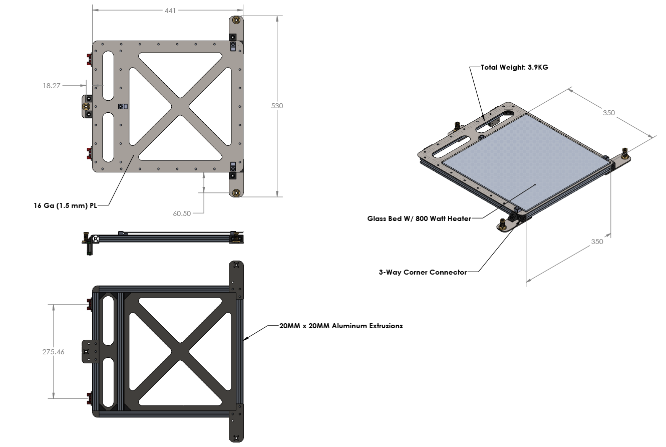
A heater applied to glass is a terrible idea. I had a Taz printer at the makerspace that was made like that. There are several problems. 1) It may/can/probably will break (the Taz did, and people on these forums report glass breakage all the time). Picking the broken glass off the heater is a PITA. 2) Glass is a poor thermal conductor and will not heat evenly (see photo below). 3) Devising a mounting system for the glass that allows it to be properly leveled can be difficult because you can't easily drill/machine glass.
Here's a thermal image of the Taz glass bed with heater attached:
Notice the 30+ C variation over the surface. How are you going to get prints to stick to that? We never could on the Taz... This is how I fixed it.
7500 mm/sec^2 is extremely ambitious for the mass you're going to be moving. You're moving two linear guides, a piece of t-slot and two extruders. That's a LOT of moving mass. 750 mm/sec^2 is a more reasonable, but probably unachievable goal. I operate my 300 mm sq bed coreXY at 700 mm/sec^2, and that's pushing it right to the edge, and I'm not moving nearly as much mass as you will be.
3 motors in Z will not stay synchronized. You will need autoleveling to avoid having to constantly relevel the bed. You will have to resync the screws frequently to keep the bed from going so far out of tram that the Z axis binds. It would be better and simpler to drive the screws with a single motor. The way you're planning to build that machine, if you put a tooling plate bed on it, you won't have to relevel it. No autoleveling will be needed. The machine will be more reliable.
Here's the design for the bed I used in my coreXY machine, Ultra Megamax Dominator. It's a kinematic mount that allows the bed to expand when heated without causing anything to bend. It has proven extremely stable in UMMD, and does not need releveling. A layer of 0.7 mm PEI on it lets everything stick well without any goop or slop.
In the Z axis I would put the two linear guides as close as possible to the two screws on the sides of the bed, and leave the one screw to support the back end of the bed by itself. It's essentially a cantilevered bed with support for the far end that would otherwise tend to bounce.
Edited 3 time(s). Last edit at 02/28/2018 12:52PM by the_digital_dentist.
Ultra MegaMax Dominator 3D printer: [drmrehorst.blogspot.com]
A heater applied to glass is a terrible idea. I had a Taz printer at the makerspace that was made like that. There are several problems. 1) It may/can/probably will break (the Taz did, and people on these forums report glass breakage all the time). Picking the broken glass off the heater is a PITA. 2) Glass is a poor thermal conductor and will not heat evenly (see photo below). 3) Devising a mounting system for the glass that allows it to be properly leveled can be difficult because you can't easily drill/machine glass.
Here's a thermal image of the Taz glass bed with heater attached:

Notice the 30+ C variation over the surface. How are you going to get prints to stick to that? We never could on the Taz... This is how I fixed it.
7500 mm/sec^2 is extremely ambitious for the mass you're going to be moving. You're moving two linear guides, a piece of t-slot and two extruders. That's a LOT of moving mass. 750 mm/sec^2 is a more reasonable, but probably unachievable goal. I operate my 300 mm sq bed coreXY at 700 mm/sec^2, and that's pushing it right to the edge, and I'm not moving nearly as much mass as you will be.
3 motors in Z will not stay synchronized. You will need autoleveling to avoid having to constantly relevel the bed. You will have to resync the screws frequently to keep the bed from going so far out of tram that the Z axis binds. It would be better and simpler to drive the screws with a single motor. The way you're planning to build that machine, if you put a tooling plate bed on it, you won't have to relevel it. No autoleveling will be needed. The machine will be more reliable.
Here's the design for the bed I used in my coreXY machine, Ultra Megamax Dominator. It's a kinematic mount that allows the bed to expand when heated without causing anything to bend. It has proven extremely stable in UMMD, and does not need releveling. A layer of 0.7 mm PEI on it lets everything stick well without any goop or slop.
In the Z axis I would put the two linear guides as close as possible to the two screws on the sides of the bed, and leave the one screw to support the back end of the bed by itself. It's essentially a cantilevered bed with support for the far end that would otherwise tend to bounce.
Edited 3 time(s). Last edit at 02/28/2018 12:52PM by the_digital_dentist.
Ultra MegaMax Dominator 3D printer: [drmrehorst.blogspot.com]
|
Re: New Printer Design February 28, 2018 01:37PM |
Registered: 10 years ago Posts: 14,672 |
Unlike digital_dentist, I favour glass plates as beds in small to medium size printers, as long as they are easily removable and you have a heat spreader between the heater and the glass. Being removable and replaceable is a key advantage IMO:
- Prints with large bases often stick to PEI and even to plain glass too well. Popping the bed + print in the freezer for a few minutes releases the print.
- The heater + bed plate take a long time to cool down after the print completes. So you have to wait a while before the print is cool enough to release from the bed. It cools down much more quickly if I remove the glass bed + print from the bed plate and stand it on its edge.
- If you do a lot of printing, as soon a one print has finished you can swap glass plates and start another after just a couple minutes of heating time.
- I have multiple glass beds with different surfaces, e.g. plain (works well with most PLA filaments), PEI, PrintBite, ABS juice etc.
The heat spreader is key to getting an even heat distribution and being able to use ordinary float glass without the risk of it cracking.
In a really large printer, removing a glass print bed is less practical, let alone putting it in the freezer, so a glass bed would make less sense.
Edited 1 time(s). Last edit at 02/28/2018 04:57PM by dc42.
Large delta printer [miscsolutions.wordpress.com], E3D tool changer, Robotdigg SCARA printer, Crane Quad and Ormerod
Disclosure: I design Duet electronics and work on RepRapFirmware, [duet3d.com].
|
Re: New Printer Design February 28, 2018 04:33PM |
Registered: 7 years ago Posts: 249 |
I used the same 20 to 40 pulley on my printer. If my eyecrometer is calibrated right, Looks like you're already planing to use 9mm closed belt for this.

|
Re: New Printer Design February 28, 2018 11:45PM |
Registered: 6 years ago Posts: 6 |
@ the_digital_dentist
I do plan to use a heat spreader, something like an 18 Ga aluminum sheet. I really prefer easily removable beds and I like to have three beds on hand, although I could do that with milled aluminum. One thing that concerns me about the milled aluminum beds is having them warp over time. I don't really have a way to measure how flat something is so problems would just gradually show up as a bunch first layer issues that I would not be able to diagnose. The reason it might warp over time is because it's heating up one side faster and cooling down faster on the other side, google "flame straightening" for a better illustration. I know bed heaters are not torches but the bed has to maintain pretty tight tolerances over hundreds of heating and cooling cycles so it might be a problem or it might no be, hard to say.
If 7500 mm/s^2 is impossible it's not because of motor torque. A 20T GT2 pulley has a pitch radius of 6.4mm, the motor has 65 N-cm of holding torque but running it at 85% of load and then loosing another 29% to micro-stepping we get 39.2 N-cm, if I can tolerate a delay of 1/16th step (~0.004 mm) than I get 9.8% of that torque so 3.8 N-cm. But geared down 3:1 that is 11.4 N-cm so divided by 6.4mm I get 17.8 N from just one motor. 17.8 N / 1.5Kg gives me an acceleration of 11,867 mm/s^2, that doesn't account for friction or the inertia of the motor and pulleys so 7500 seems reasonable. 750 mm/s^2 would mean a force of 1.125 N which seems very low to me.
Is there anything wrong with hooking the Z motors in parallel to the same driver? Or will they still get out of sync? I wouldn't expect them to skip steps or back drive when the power is off. I can do a pulley arrangement with one motor but I loose some Z travel. Sounds like it might be worth it though. I would like to move the linear guides to the sides but I don't have room in the heated chamber. I would loose about 40mm of X travel so I just tried to make the bed rigid and I'll do my best to straighten the screws and align them.
@DC42
I also like how having multiple beds on hand, it lets you make better use of build surfaces especially when they're expensive. I can really use up buildtak sheets when I can nest small parts on the spots that are still good.
@prot0typ1cal
When googling around for ideas for printers I came across pictures of your Hlidskjalf and it inspired this one even though mine won't be nearly as impressive. Yes those are 9mm belts on the gearing but it's 3:1 ratio 60 and 20 tooth pulleys. Based on your experience do you think 3:1 is too much? I know it's going to limit travel speed but I think print speeds will benefit from better resolution and torque.
|
Re: New Printer Design March 01, 2018 03:18AM |
Registered: 8 years ago Posts: 5,232 |
All that cross bracing will make it difficult to remove the print. Is there enough room to move it out through the top?
With closed loop belts for XY axis, you have the chance to mount the steppers outside of the enclosure. The Z-steppers could be below the enclosure.
I wouldn't use bearings at the top of the lead screws. Maybe add a thrust bearing at the back of the Z-steppers. IDK how robust the motors bearings are against axial load.
Pretty curious to hear more about the kevlar core belts. Ringing/overshooting from belt stretch is always a matter with bigger 3D printers.
|
Re: New Printer Design March 01, 2018 06:30AM |
Registered: 10 years ago Posts: 14,672 |
If you use geared motors, you may have problems with maximum speed due to stepper motor inductance and back emf. Calculate what steps/mm you will get, then plug that and your stepper motor parameters into the calculator at reprapfirmware.org to check.
I am not sure that using a thin aluminium heat spreader under a thicker glass bed is a good idea, especially when the bed is large. The problem is, the aluminium will try to expand when the heater is turned on. If it is clamped to the glass at the edges, it will tend to adopt a slight dome shape bulging away from the glass. So the centre will not be in good contact with the glass, and heating will be less uniform. My Cartesian printer uses this arrangement, with a PCB bed heater under the heat spreader, and seems to work OK although the bed is only 210x210mm and I rarely heat it to more than 70C indicated temperature. My delta uses 5mm thick aluminium instead, 330mm diameter with 4mm glass on top.
I doubt that heating and cooling the aluminium repeatedly will warp it if it is a common aluminium alloy. Concorde survived heating to 100-120C and back on every flight due to kinetic heating and was rated for 25 years service.
Edited 5 time(s). Last edit at 03/01/2018 06:39AM by dc42.
Large delta printer [miscsolutions.wordpress.com], E3D tool changer, Robotdigg SCARA printer, Crane Quad and Ormerod
Disclosure: I design Duet electronics and work on RepRapFirmware, [duet3d.com].
|
Re: New Printer Design March 01, 2018 08:14AM |
Registered: 11 years ago Posts: 5,780 |
One of my printers has been using the same 1/4" cast tooling plate bed for over 4 years of almost daily printing and it is as flat as the day it was installed.
It doesn't matter if the Z motors are driven in parallel. They will get out of sync. You can resync them automatically by driving the bed beyond the bottom of the Z axis when you power up or before you start printing (assuming you have stops on the screws that force the bed support to a level position). It probably won't sound nice, but it should work. You don't need antibacklash nuts on the Z axis. Gravity will keep the nuts in contact with the screw threads at all times. There won't be any backlash.
How are you going to enclose and heat with that frame design? How will you remove prints or change glass plates with bracing on all four sides of the frame? Normally you want the screw located close to the guides...
Even if you use glass plates, I'd still recommend using a piece of tooling plate for the heat spreader. A piece of 18 gauge aluminum that size will not sit flat when supported at 3 points. You're worried about tooling plate warping over time, but what do you think a piece of 18 gauge sheet is going to do when you heat it up? It's going to expand and push against the leveling screws. Something is going to bend, probably the thing that is easiest to bend: the sheet metal.
That will create air gaps between the aluminum and the glass so the glass won't heat evenly. Prints don't like to stick to unevenly heated surfaces. Maybe the glue will fix that...
Ultra MegaMax Dominator 3D printer: [drmrehorst.blogspot.com]
|
Re: New Printer Design March 01, 2018 10:10AM |
Registered: 8 years ago Posts: 622 |
Ref the desired acceleration, if you manage to achieve 7500 mm/sec^2 you won't want to use it. It's just too fast and will cause all sorts of problems with print quality - that's if it doesn't shake the printer apart!
If you do the maths, to get to 200 mm/sec non print speed @ 7500 mm/sec^2 will take 0.027 secs and the print head will move 2.667mm during that acceleration phase. For print moves, the time to accelerate up to 100mm/sec will be 0.013 secs and the print head will move only 0.667mm from standstill to max print speed. For good quality prints, you need smooth acceleration. 7,500 mm/sec^2 is more akin to sudden jerks.
The other big factor is that there is no way on God's earth that you could accelerate the melt rate and extrusion of the filament at anything like those speeds. If you try, all you'll get is a pressure pulse but the molten filament won't accelerate out of the nozzle as fast as the print head, so you'll get under extrusion at the start of every move.
So, settle for a useable acceleration of (say) 1200 mm/sec^2. Using that, non print moves up to 200 mm/sec will take 0.167 sec move a distance of 16.667 mm and print moves up to 100mm/sec will take 0.083 secs over 4.167 mm. You could probably use double that acceleration but see how it prints. In any case, this negates the need for the complexity and cost of the gearing and associated back lash problems which are almost certain to be an issue.
Just my twopence worth............
[somei3deas.wordpress.com]
[www.youtube.com]
|
Re: New Printer Design March 01, 2018 10:57AM |
Registered: 11 years ago Posts: 335 |
I wouldn't be worried about tooling plate flatness. You can't generate a meaningful temperature gradient because it will take 10+ minutes to heat and has very high thermal conductivity.
I think you are underestimating the difficulty of achieving high accelerations. Acceleration is generally limited by the frame, not by the motors, because as you have noted it is quite easy to buy a larger motor or obtain torque in other ways. On the other hand, it doesn't take much force to deflect the end-effector by ~0.1mm relative to the bed, and that kind of error will be visible in the final print.
A kilogram of force might not sound like much on paper, but as a fast impulse it has punch. Even worse, infill patterns have a way of hitting reasonant frequencies which can be very unpleasant. I have a printer that can reach 10m/s2 of acceleration and it feels like the printer and desk are being hit with a mallet.
At high accelerations pretty much everything becomes suspect, for example an E3D v6 heatsink hanging out of a plastic groovemount will swing around like a wet noodle. You also need to worry about the machine walking away.
Note that it is absolutely essential that your belts are under more tension than the peak force they will be carrying* which means that to obtain your desired acceleration you will probably want 2+Kg of tension on each belt. (*Or the loose side will repeatedly go slack then snap back which ruins motion quality and may damage the belt.)
|
Re: New Printer Design March 01, 2018 11:06AM |
Registered: 11 years ago Posts: 335 |
Quote
deckingman
The other big factor is that there is no way on God's earth that you could accelerate the melt rate and extrusion of the filament at anything like those speeds. If you try, all you'll get is a pressure pulse but the molten filament won't accelerate out of the nozzle as fast as the print head, so you'll get under extrusion at the start of every move.
At infinite acceleration the print head can instantaneously change direction and therefore its speed never changes. Low accelerations force you to constantly vary print speed (depending on how long your line segments are) which creates blobbing and related artifacts.
At high accelerations you only run into problems at the start and end of a complete segment or layer, and if you can rapid to the new print location fast enough even that becomes irrelevant. The extruder can spend the entire print pushing filament at a single constant speed.
|
Re: New Printer Design March 01, 2018 02:43PM |
Registered: 8 years ago Posts: 622 |
So on the one hand you say this...............
and on the other hand you say...........
[somei3deas.wordpress.com]
[www.youtube.com]
Quote
......... it doesn't take much force to deflect the end-effector by ~0.1mm relative to the bed, and that kind of error will be visible in the final print.
A kilogram of force might not sound like much on paper, but as a fast impulse it has punch. Even worse, infill patterns have a way of hitting reasonant frequencies which can be very unpleasant. I have a printer that can reach 10m/s2 of acceleration and it feels like the printer and desk are being hit with a mallet.
At high accelerations pretty much everything becomes suspect, for example an E3D v6 heatsink hanging out of a plastic groovemount will swing around like a wet noodle. You also need to worry about the machine walking away.
and on the other hand you say...........
Quote
At infinite acceleration the print head can instantaneously change direction and therefore its speed never changes. Low accelerations force you to constantly vary print speed (depending on how long your line segments are) which creates blobbing and related artifacts.
At high accelerations you only run into problems at the start and end of a complete segment or layer, and if you can rapid to the new print location fast enough even that becomes irrelevant. The extruder can spend the entire print pushing filament at a single constant speed.
[somei3deas.wordpress.com]
[www.youtube.com]
|
Re: New Printer Design March 01, 2018 02:47PM |
Registered: 7 years ago Posts: 249 |
Quote
Speaker-2-Animals
@prot0typ1cal
When googling around for ideas for printers I came across pictures of your Hlidskjalf and it inspired this one even though mine won't be nearly as impressive. Yes those are 9mm belts on the gearing but it's 3:1 ratio 60 and 20 tooth pulleys. Based on your experience do you think 3:1 is too much? I know it's going to limit travel speed but I think print speeds will benefit from better resolution and torque.
Thanks, I'm sure yours will be great, and you're starting will all metal construction to start.
A higher ratio will help with resolution and acceleration.
Most steppers drop torque around 1000 steps/sec, for 200 pulse (1.8 degree) steppers that's 5 revs/sec.
At 3:1 (60T:20T with 2mm pitch belts/pulleys) you will lose torque above 67mm/sec feed rates. Of course you started with 3x more torque.
However, this will significantly help move heavier gantry and carriages, especially with direct drive extruders.
Hlidskalf printed not so reliably at 100mm/sec, per design. Though I kept breaking most of the printed PLA brackets and am now rebuilding with all aluminum.
Stratasy's Dimension printers also use a high ratio, due to the bulky carriage inside a heated chamber. They print at relatively slow speeds, ~45mm/sec. At least the older models did. And use NEMA 23's and 9mm belts all around.
About the "X" in front, 4x large triangle gussets in the corners will provide ample rigidity, and allow access to the print bed.
Eager to see the finished printer, G'luck!
Edited 1 time(s). Last edit at 03/01/2018 02:54PM by prot0typ1cal.
|
Re: New Printer Design March 01, 2018 02:57PM |
Registered: 6 years ago Posts: 6 |
@o_lampe
I'm going to see how annoying it is to work around the cross bracing and perhaps remove the front cross brace if it's in the way too much.
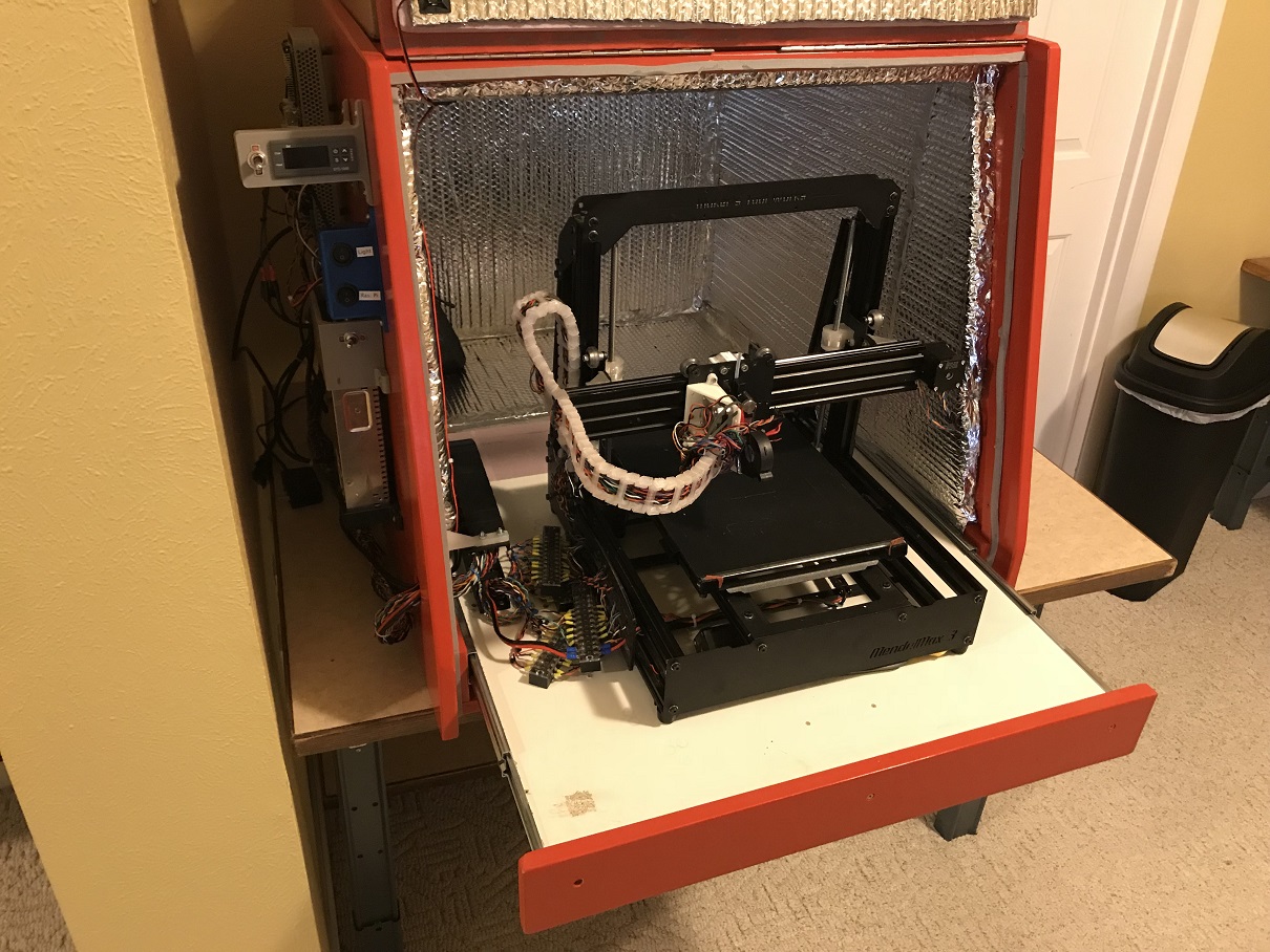
The enclosure is already built and the printer sits on a shelf inside so I can't put the motors outside. The attachment is a photo of it.
The LMF08 bearings are pretty cheap I think I'll try it with and without them, the motors are integrated with the lead screw like this one:
So I would hope they are ok with axial loads but watching a video of a tear down it looks like they are normal steppers with a bigger bore through the armature.
These are the belts, not too expensive but the shipping to the US is outrageous.
[reprapworld.com]
I'll see if I can do some kind of stretch comparison with the remnants.
@dc42
According to the calculator I don't exceed the supply voltage until I'm at 210 mm/s. The step pulse frequency looks ok too at x32 microstepping. This is with a 6 tooth pulley and my setup is more like 6.67 so 230mm/s should be fine. Thanks for the link.
350 mm of aluminum would expand about 0.8 mm over 100 degree temperature change so I can avoid clamping too tightly and leave some room around the edges. But this has made me realize that the cross bracing will expand 0.3 mm less than the frame in the heated enclosure because steel has a different CTE so I probably need go with aluminum on that too. Same goes for the Z platform which is also steel plate on aluminum frame.
Yeah it's totally possible that fairly even low intensity heat does negligible warping but I'm pretty sure it does some, one reason airplanes have limited service lives is because aluminum has no definite yield point and therefore fatigues worse than steel.
@the_digital_dentist
I will redesign the Z actuators around a single motor with pulleys. I see your point about the anti-backlash nuts, does that still apply if you do auto-leveling and the nuts are being driven back and forth?
The heated build volume is already built, the attachment is a picture of it.
Where did you get your tooling plate, I see some with a flatness tolerance of 0.015" which is about 1 layer height, that doesn't seem suitable. 0.8mm of expansion seems manageable if the spreader isn't clamped too tightly and is a little smaller than the glass.
@deckingman
I think the frame will be reasonably stiff but you're right acceleration is probably limited by something other than motor torque. I am trying to overbuild all the components so I get the best acceleration possible.
@691175002
I also think being capable of high (and stable) accelerations is important to print quality. The nozzle lingering too long on overhangs has been very annoying to deal with on my current printer.
I'm going to see how annoying it is to work around the cross bracing and perhaps remove the front cross brace if it's in the way too much.
The enclosure is already built and the printer sits on a shelf inside so I can't put the motors outside. The attachment is a photo of it.
The LMF08 bearings are pretty cheap I think I'll try it with and without them, the motors are integrated with the lead screw like this one:

So I would hope they are ok with axial loads but watching a video of a tear down it looks like they are normal steppers with a bigger bore through the armature.
These are the belts, not too expensive but the shipping to the US is outrageous.
[reprapworld.com]
I'll see if I can do some kind of stretch comparison with the remnants.
@dc42
According to the calculator I don't exceed the supply voltage until I'm at 210 mm/s. The step pulse frequency looks ok too at x32 microstepping. This is with a 6 tooth pulley and my setup is more like 6.67 so 230mm/s should be fine. Thanks for the link.
350 mm of aluminum would expand about 0.8 mm over 100 degree temperature change so I can avoid clamping too tightly and leave some room around the edges. But this has made me realize that the cross bracing will expand 0.3 mm less than the frame in the heated enclosure because steel has a different CTE so I probably need go with aluminum on that too. Same goes for the Z platform which is also steel plate on aluminum frame.
Yeah it's totally possible that fairly even low intensity heat does negligible warping but I'm pretty sure it does some, one reason airplanes have limited service lives is because aluminum has no definite yield point and therefore fatigues worse than steel.
@the_digital_dentist
I will redesign the Z actuators around a single motor with pulleys. I see your point about the anti-backlash nuts, does that still apply if you do auto-leveling and the nuts are being driven back and forth?
The heated build volume is already built, the attachment is a picture of it.
Where did you get your tooling plate, I see some with a flatness tolerance of 0.015" which is about 1 layer height, that doesn't seem suitable. 0.8mm of expansion seems manageable if the spreader isn't clamped too tightly and is a little smaller than the glass.
@deckingman
I think the frame will be reasonably stiff but you're right acceleration is probably limited by something other than motor torque. I am trying to overbuild all the components so I get the best acceleration possible.
@691175002
I also think being capable of high (and stable) accelerations is important to print quality. The nozzle lingering too long on overhangs has been very annoying to deal with on my current printer.
|
Re: New Printer Design March 01, 2018 03:48PM |
Registered: 10 years ago Posts: 14,672 |
I agree with the above posts that tooling plate would be a good choice and that you won't be able to use high accelerations because the machine would shake itself to bits. I suggest you aim for 2000 to 3000 mm/sec^2. I still think it is better to avoid gearing on the X and Y axes.
You could use 3 separate Z motors and use the automatic bed levelling feature of the Duet. This is completely different from bed compensation (which is mistakenly often called bed leveling). It would also allow you to eliminate the bed levelling screws. The disadvantage is cost, because as well as 2 extra stepper motors you will need a DueX2 expansion board to provide the additional stepper driver, so that the 3 Z motors can be driven independently.
Large delta printer [miscsolutions.wordpress.com], E3D tool changer, Robotdigg SCARA printer, Crane Quad and Ormerod
Disclosure: I design Duet electronics and work on RepRapFirmware, [duet3d.com].
|
Re: New Printer Design March 01, 2018 04:44PM |
Registered: 11 years ago Posts: 335 |
Quote
deckingman
So on the one hand you say this..............
At low accelerations the printer must slow down at every corner. This slowdown is difficult to synchronize with the extruder because the melt chamber and general compliance acts as a low-pass filter.
At high acceleration the printer can pass through the corners more quickly, so extruder synchronization becomes less important. At extremely high accelerations the printer might not have to slow down at all, which is very hard on the frame but competely bypasses the need for pressure advance since the speed of the printer never changes (only its direction).
So acceleration is good from an extruder-synchronization standpoint but can also introduce massive ringing and other artifacts if the frame can't keep up.
(*On the other hand if you are starting or stopping, as opposed to changing direction, high acceleration works against you)
Here is an example print at 5000mm/s2 and 60mm/s with no pressure advance: [imgur.com]
The printer itself can go much faster but I need to replace some plastic with aluminum.
Edited 1 time(s). Last edit at 03/01/2018 04:58PM by 691175002.
|
Re: New Printer Design March 01, 2018 05:03PM |
Registered: 11 years ago Posts: 5,780 |
Unless it's made of upsidaisium, the bed can't go up if the screw threads aren't pushing it, and it can't go down unless the screw threads turn and allow it. No backlash.
I've heard the argument about tooling plate flatness before, mostly from people who use glass beds. There are a couple problems with it. First, the spec on tooling plate flatness is for a full size sheet (I don't recall how big it is exactly, but it was something like 4'x9' or 4'x12'). Smaller pieces are generally much flatter. Guide rail sag, frame sag, variations in plate flatness, variation in print surface (PEI, glass, build-tak, etc.) thickness, variation in adhesive thickness (under the PEI, build-tak, gino pads, etc.) ultimately limits the minimum layer thickness you can use with any given bed assembly.
Second, unless you're using optical blanks, glass comes without any flatness spec. Rightly or wrongly, people simply trust it to be flat enough, even as they argue against tooling plate because they don't understand the flatness spec it comes with.
Third, the thermal conductivity of the aluminum in intimate contact with the print surface- (PEI or build-tak, etc., but not glass) ensures even heating. As soon as you put a piece of glass into the mix, you can no longer guarantee even heating. Then come the gino pads, and the glue, and the abs juice, and the hairspray, etc., to try to get prints to stick. Meh.
I've put tooling plate beds with PEI print surfaces into 2 of my printers and a Taz at the makerspace. I have no qualms about printing from one edge to the other (though the guide rail sag in the Taz makes that a little iffy, as it would for a glass plate, too).
Thermal expansion of the heat spreader will push it against the leveling screws. Something will have to flex. If the leveling screws are anchored in a thin piece of metal it will flex. If the heat spreader is thin, it will flex (and there goes your contact with the glass sitting on top of it). It might work OK or it might not. It is absolutely a non issue with a kinematic mount. The bed plate can expand all it wants and it will slide (in a controlled way) on the leveling screw heads. Nothing has to bend.
Edited 1 time(s). Last edit at 03/01/2018 09:52PM by the_digital_dentist.
Ultra MegaMax Dominator 3D printer: [drmrehorst.blogspot.com]
|
Re: New Printer Design March 01, 2018 06:57PM |
Registered: 8 years ago Posts: 338 |
|
Re: New Printer Design March 02, 2018 04:36AM |
Registered: 10 years ago Posts: 14,672 |
The IR sensor works reasonably well on plain glass backed with black paper, but I don't recommend it if you put coatings on the glass. I print PLA on to glass without a coating.
Large delta printer [miscsolutions.wordpress.com], E3D tool changer, Robotdigg SCARA printer, Crane Quad and Ormerod
Disclosure: I design Duet electronics and work on RepRapFirmware, [duet3d.com].
Large delta printer [miscsolutions.wordpress.com], E3D tool changer, Robotdigg SCARA printer, Crane Quad and Ormerod
Disclosure: I design Duet electronics and work on RepRapFirmware, [duet3d.com].
|
Re: New Printer Design March 08, 2018 11:40AM |
Registered: 6 years ago Posts: 6 |
I did some more designing on this and made some significant changes.
First the_digital_dentist has sold me on the mic6 plate. But I will embed high temp neodymium magnets into the underside so I can use a thin spring steel sheet to make the print surface easily removable. Very similar to the Buildtak flex plate system. The top side of the aluminum will be undisturbed by the magnets so I could still print directly onto that. The aluminum plate will be fastened as shown in the picture so I reckon this will allow for thermal expansion and also does not allow the plate to move around. I will probably put some silicon rubber where it contacts the bolts.
For the z axis screws I think I will get the expansion board and do the automatic bed leveling. This saves me some Z height since putting pulleys on the lead screws eats up some room. It also looks cool (not that it's a major consideration). It is like ~80 dollars more expensive to go this route though. I just tell myself snowmobiles are expensive too and nobody questions spending money on them. I also will use delrin leadnuts instead of the brass anti-backlash type.
The other big change is going with docking type dual extruders instead of the parking extruders. The whole X axis assembly is now less than 1 KG. The rail is an MGN9C. I have a plan for making all these parts at home but if that fails I have a machinist who owes me a favor.


First the_digital_dentist has sold me on the mic6 plate. But I will embed high temp neodymium magnets into the underside so I can use a thin spring steel sheet to make the print surface easily removable. Very similar to the Buildtak flex plate system. The top side of the aluminum will be undisturbed by the magnets so I could still print directly onto that. The aluminum plate will be fastened as shown in the picture so I reckon this will allow for thermal expansion and also does not allow the plate to move around. I will probably put some silicon rubber where it contacts the bolts.

For the z axis screws I think I will get the expansion board and do the automatic bed leveling. This saves me some Z height since putting pulleys on the lead screws eats up some room. It also looks cool (not that it's a major consideration). It is like ~80 dollars more expensive to go this route though. I just tell myself snowmobiles are expensive too and nobody questions spending money on them. I also will use delrin leadnuts instead of the brass anti-backlash type.
The other big change is going with docking type dual extruders instead of the parking extruders. The whole X axis assembly is now less than 1 KG. The rail is an MGN9C. I have a plan for making all these parts at home but if that fails I have a machinist who owes me a favor.


Sorry, only registered users may post in this forum.