Building an Ormerod 2 from scratch
Posted by sinnedwrong
|
Building an Ormerod 2 from scratch August 06, 2017 01:18PM |
Registered: 8 years ago Posts: 26 |
Having bought an Ormerod 2 (a 528.5) kit from RepRapPro a couple of years ago I thought I would attempt the "RepRap" principle by building one from scratch. Clearly I can print the relevant parts and I have bought the very nice aluminium X-axis and bed from the relevant suppliers. As my current machine is working I haven't yet risked dismantling my existing machine to install them, hence the new build which will also give me the opportunity to play with DC's new firmware.
My questions relate to the acrylic Y-axis end plates A & B, which I assume are mirror imaged versions of the same DXF, to get the slight taper for the 12mm rod to be from the alternative sides
1 Does anybody supply these items, possibly in aluminium? I'm aware that the Duet/power supply assembly also require acrylic pieces and that this assembly braces the Z axis. Problem for another day.
2 I have found the DXF files which I think are for (? some ) of the acrylic and MDF pieces in GitHub [github.com]. I have an MPCNC 2.8w laser machine that I have built. Anyone got ideas of what power laser is needed to cut acrylic. I suspect 2.8W will be too small.
I'm aware there are other alternative design around for these pieces, which are meant to stop the Y axis twisting issue but at this point I thought I would start with the original.
Thanks in advance
Dennis
Dennis
|
Re: Building an Ormerod 2 from scratch August 07, 2017 08:40AM |
Registered: 10 years ago Posts: 2,472 |
As you are building from scratch, you might consider changing the end-plate design so that the position of the ground rods can be adjusted to make them exactly parallel in Z. This will prevent the situation where the bed rises and falls as it moves in Y, which is a major reason why it is difficult to mechanically level the bed. A mechanical screw adjustment will also eliminate the need to make holes that are an exact (or slightly tapered) fit on the rods.
Dave
[Edit] By coincidence there is a thread on that very issue here [forums.reprap.org]
Edited 1 time(s). Last edit at 08/07/2017 08:41AM by dmould.
Dave
[Edit] By coincidence there is a thread on that very issue here [forums.reprap.org]
Edited 1 time(s). Last edit at 08/07/2017 08:41AM by dmould.
|
Re: Building an Ormerod 2 from scratch August 20, 2017 07:30AM |
Registered: 8 years ago Posts: 26 |
Hi,
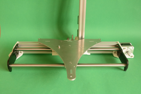
As 125 people have viewed my earlier posting I thought I would update the board on progress to date. I have attached a photo of the build to date and to answer the specific question in my earlier post a 2.8W 445nm laser mounted on an MPCNC device successfully cut 5mm thick Perspex at 1mm/" speed with a Z drop of 1mm. This took about 30minutes for each Y axis end plate and I am now making the Perspex mounts for the Mean Well power supply. I have posted an update on the posting that DMOULD highlighted with an attachment
shows the different end plate design that RepRapPro published for their different version numbers. I am trying the 528.5 version that have 2 lugs that locate into the aluminium extrusion. Time will tell if that prevents the Y axis twist!
Dennis
|
Re: Building an Ormerod 2 from scratch August 20, 2017 04:09PM |
Registered: 10 years ago Posts: 1,230 |
Thank's for the update! - keep 'em coming - we need this! :-)
to make a picture appear in post:
"Attach a file"
"Choose File"
"Attach"
"create link in message"
Work for me with Firefox, Opera, Brave etc.
Erik
to make a picture appear in post:
"Attach a file"
"Choose File"
"Attach"
"create link in message"
Work for me with Firefox, Opera, Brave etc.

Erik
|
Re: Building an Ormerod 2 from scratch September 02, 2017 09:09AM |
Registered: 8 years ago Posts: 26 |
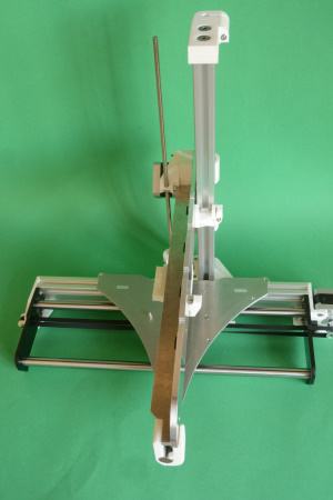
Following Erik's last message time for an update and an attempt to embed an image in the posting. Successfully assembled Y,X and Z axes. The Y carriage required a bit of fettling otherwise all straightforward. Cut out the 3mm heated bed insulator with 6 passes of 0.6mm per pass with my 2.8W laser and have been waiting for miscellaneous electronic components (in particular the SMD LEDs and resistor for the bed) to arrive. Still to produce the aluminium heat spreader and my plan is to use cable rated at 17A for the bed and 26AWG wire for the thermistor.
After that it will be time for decisions:
1 Use Duet 0.6 as per original or one of the newer Duets. If the latter do I go for Wi-Fi (and in suburban west London, there are according to insider 4, at least 15 other Wi-Fi users local to me on the Wi-Fi channel I am using) or stay with cabled Ethernet? As far as I can see the major advantage to the later Duets is the much easier option to add a second extruder should I want to. Still have to work out how to mount the Duet. I see printed designs on Thingiverse and I'm hoping (assuming?) that all duets have the same profile and fixing points so the designs are interchangeable.
2 Do I cheat and purchase wiring looms or assemble my own. My understanding is the plugs for the steppers are JST-PH and connections to the Duets are Molex KK although Ian from RepRapPro in 2015 listed connectors and at that time was recommending Toby 1800-T connectors. I have been very impressed with Toby for other supplies. Cables would be 26AWG inside Shrinktek expandable sleeving, I'm not bothered about EMI proofing this build.
I would be interested in any thoughts people might have on these points.
Dennis
|
Re: Building an Ormerod 2 from scratch September 02, 2017 10:27AM |
Registered: 8 years ago Posts: 26 |

OK so using IE11 the attach file, create link in message didn't work. Trying with firefox!
|
Re: Building an Ormerod 2 from scratch September 03, 2017 07:08AM |
Registered: 10 years ago Posts: 14,672 |
If WiFi is congested where you are, I suggest the Duet Ethernet. It has the same advantages of the Duet WiFi (TMC2660 drivers with x256 microstepping etc.) but with cabled Ethernet. Connectors are supplied with the Duet WiFi and Duet Ethernet.
Depending on where you get the stepper motors from, they may have wires coming out of them, or JST connectors.
Large delta printer [miscsolutions.wordpress.com], E3D tool changer, Robotdigg SCARA printer, Crane Quad and Ormerod
Disclosure: I design Duet electronics and work on RepRapFirmware, [duet3d.com].
|
Re: Building an Ormerod 2 from scratch October 08, 2017 06:05PM |
Registered: 8 years ago Posts: 123 |
Any further update sinnedwrong? I've been watching your post with interest , so I'll post about where I am in the hope it'll spur you on to do so 
I'm making my second Ormerod 2 at the moment as way of upgrading my existing one without dismantling my fairly original 528.4 work-horse (although I changed the extruder on the original last night as it's a simple update as I've been getting itchy to try out the new build).
I ended up with all the parts for a second Ormerod 2 last December when I bought a lot on eBay when I was just after the parts for a dual extruder and ended up with almost all the parts minus a few cheap minor parts such as a bowden end and hobbed nut) (original post is here)
I've made very little time for it this year until this last month. So now I've picked it up again and have been working gently on it (half hour here, an hour there). I am currently waiting on MDF insulator from Reprap Ltd (I thought I had it, but realised when it came to fitting that it wasn't a Quickset MDF insulator) so I figured I could make time for a post. I'm hoping to be finished in the next couple of weeks if I can.
I have, or plan to have, on this build
528.5 and additional/replacement parts
I've considered the Spring-loaded extruder but I've never really had any issues with my extruder, so I think I'll leave that for the next build (i.e. rebuilding my current working 528.4 when completely happy with this one)
I did briefly consider getting all the printed parts professionally printed via SLS in nylon for that "it's just pucka" feel, but that's just silly
This week I'm now torn between transplanting my existing Duet (I really only need one printer ) or buying a nice shiny Duet Wifi and having two working Ormerod 2's.
I'm making my second Ormerod 2 at the moment as way of upgrading my existing one without dismantling my fairly original 528.4 work-horse (although I changed the extruder on the original last night as it's a simple update as I've been getting itchy to try out the new build).
I ended up with all the parts for a second Ormerod 2 last December when I bought a lot on eBay when I was just after the parts for a dual extruder and ended up with almost all the parts minus a few cheap minor parts such as a bowden end and hobbed nut) (original post is here)
I've made very little time for it this year until this last month. So now I've picked it up again and have been working gently on it (half hour here, an hour there). I am currently waiting on MDF insulator from Reprap Ltd (I thought I had it, but realised when it came to fitting that it wasn't a Quickset MDF insulator) so I figured I could make time for a post. I'm hoping to be finished in the next couple of weeks if I can.

I have, or plan to have, on this build
528.5 and additional/replacement parts
- Ormerod Y-Axis bed leveling adjustment
- Ormerod Anti Backlash Z Nut
- A white Ormerod X Stop
- Ormerod X-idler bracket with belt tensioner
- iamburnys Extruder Gears & Z gears & Replacement Extruder Tube Clip
- chrishamm's y-front-clamp
I've considered the Spring-loaded extruder but I've never really had any issues with my extruder, so I think I'll leave that for the next build (i.e. rebuilding my current working 528.4 when completely happy with this one)
I did briefly consider getting all the printed parts professionally printed via SLS in nylon for that "it's just pucka" feel, but that's just silly
This week I'm now torn between transplanting my existing Duet (I really only need one printer
) or buying a nice shiny Duet Wifi and having two working Ormerod 2's. |
Re: Building an Ormerod 2 from scratch October 15, 2017 03:09AM |
Registered: 9 years ago Posts: 1,699 |
I did my OM2 from scratch. The spring loaded extruder is really a great improvement. Next step will be a TR8 leadscrew.
Slicer: Simplify3D 4.0; sometimes CraftWare 1.14 or Cura 2.7
Delta with Duet-WiFi, FW: 1.20.1RC2; mini-sensor board by dc42 for auto-leveling
Ormerod common modifications: Mini-sensor board by dc42, aluminum X-arm, 0.4 mm nozzle E3D like, 2nd fan, Z stepper nut M5 x 15, Herringbone gears, Z-axis bearing at top, spring loaded extruder with pneumatic fitting, Y belt axis tensioner
Ormerod 2: FW: 1.19-dc42 on Duet-WiFi. own build, modifications: GT2-belts, silicone heat-bed, different motors and so on. Printed parts: bed support, (PSU holder) and Y-feet.
Ormerod 1: FW: 1.15c-dc42 on 1k Duet-Board. Modifications: Aluminium bed-support, (nearly) all parts reprinted in PLA/ ABS, and so on.
|
Re: Building an Ormerod 2 from scratch October 16, 2017 10:19AM |
Registered: 8 years ago Posts: 26 |
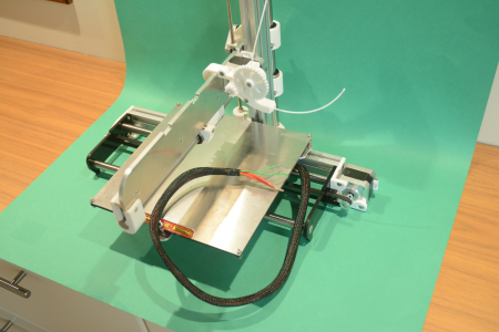
Sorry for the delay in updating this build. Something to do with owning a classic car, a boat and the imminent arrival of winter. Progress to date:
1 I assembled the heated bed, cutting out the MDF using several passes of my 2.8W laser but encountered all of the usual problems when trying to cut out the aluminium heat spreader using a CNC router. Melted chips, loss of registration, destruction of the bit etc. So eventually went back to the old fashioned way and used a pad saw. When attempting to solder the SMD resistor to the heated bed the pad came loose. As I manage on my original Ormerod without LEDs to tell me if its active I didn't pursue trying to repair the bed and will manage without. My stock of 35mm cap head M3 screws are only partially threaded so I used a 35mm hex headed bolt instead for the bed mounting screw at the front of the machine.
2 Assembled the extruder with no problems
3 Have now sourced all of the components for the "Quickset" hot end so that's the next task.
4 Have sourced all of the connectors and 2 (Engineer PA-09 and PA-21) generic crimp tools (one can never have too many crimp tools)! So after the hot end the next stage will be to assemble the wiring looms. However I have still to decide how to mount the duet which will determine the length of the looms. I like the idea of using the Meanwell power supply to brace the Z axis however I'm struggling at the moment to see how the mount a "printed" duet case onto the power supply. After my experience with the aluminium for the heated bed I don't fancy trying to reproduce the original mounts.
Dennis
|
Re: Building an Ormerod 2 from scratch November 18, 2018 07:40AM |
Registered: 8 years ago Posts: 26 |
Hi all
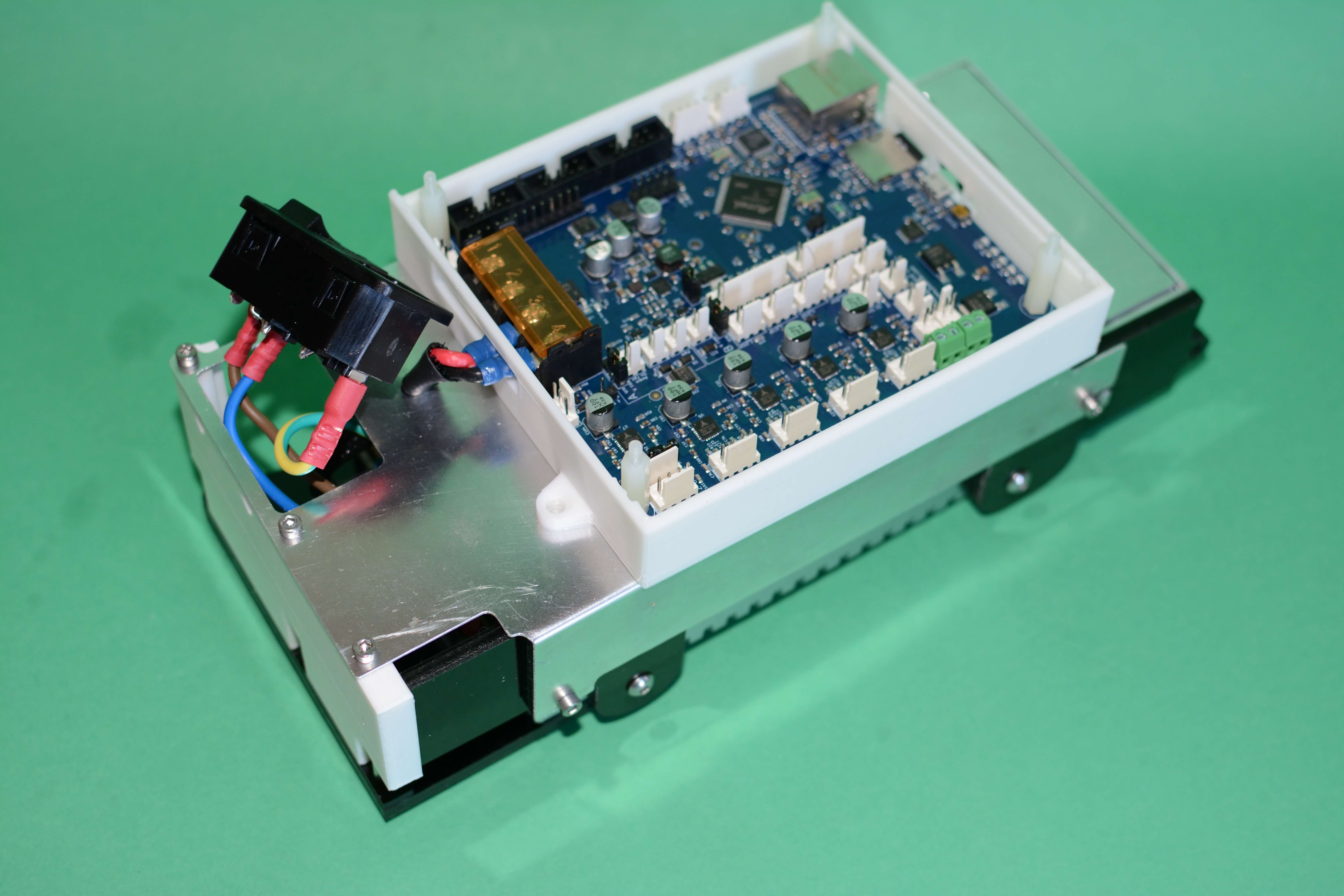
Long time since last update, not all of which I can blame on waiting for the Duet Maestro to be available, however assuming the attached image works you can see I have now completed the electronics section of the build. I cut the aluminium mount using my homebuilt MPCNC router with a 1/8" carbide single flute bit, Estlcam CAM software and a trochoidal cut. The Maestro enclosure is from [www.thingiverse.com].
After mounting the electronics on the frame the wiring is next and I have some questions for the experts:
1 What size of cable should I use for wiring the motors and the Quickset hot end?
2 I have a spare original reprappro Z probe but if I decide to use DC42s better probe does this still work with a white label for the x axis end stop or would I need to paint the end stop black similar to the website advice for the aluminium print bed
3 Long shot but does anybody know of a published design for a lid for the maestro enclosure. I know I can knock one up in Openscad but I was just wondering.
Updates to follow, hopefully without such a long interval
Dennis
|
Re: Building an Ormerod 2 from scratch November 18, 2018 08:35AM |
Registered: 8 years ago Posts: 123 |
|
Re: Building an Ormerod 2 from scratch November 18, 2018 08:58AM |
Registered: 8 years ago Posts: 26 |
Sorry! For a PhD scientist that was very sloppy, by size of wire I meant diameter (I don't care if its AWG or fractions of a mm I can convert) My concern is for current carrying capacity and or voltage drop.
As regards the print bed yes it will be like the original Ormerod a glass plate on top of the aluminium heat spreader. Reading [escher3d.com] I see that the issue of reflections from top/ bottom / aluminium surface is an issue to address, after I have sourced a piece of glass which raises another question: what specification of glass (other than flat) is required. Soda glass, borosilicate or ??
Thanks for the prompt reply
Dennis
|
Re: Building an Ormerod 2 from scratch November 18, 2018 10:44AM |
Registered: 10 years ago Posts: 14,672 |
Quote
sinnedwrong
what specification of glass (other than flat) is required. Soda glass, borosilicate or ??
Ordinary 3mm float glass from your local glass and glazing supplier. Ask him to cut it to size and smooth off the sharp edges so that it is safe to handle.
Edited 2 time(s). Last edit at 11/18/2018 10:45AM by dc42.
Large delta printer [miscsolutions.wordpress.com], E3D tool changer, Robotdigg SCARA printer, Crane Quad and Ormerod
Disclosure: I design Duet electronics and work on RepRapFirmware, [duet3d.com].
|
Re: Building an Ormerod 2 from scratch November 18, 2018 04:23PM |
Registered: 8 years ago Posts: 123 |
I don't know enough about such things personally, but I can tell you what I can.Quote
sinnedwrong
Sorry! For a PhD scientist that was very sloppy, by size of wire I meant diameter (I don't care if its AWG or fractions of a mm I can convert) My concern is for current carrying capacity and or voltage drop.
The supplied motor looms e.g. [emaker.io] and [reprapltd.com] have very thin wires. I measure 1mm in diameter with my digital calipers including the plastic sheath.
For the hotend these wires were simply "doubled up" by reprappro, I assume due to the higher current demand.
|
Re: Building an Ormerod 2 from scratch November 26, 2018 10:48AM |
Registered: 8 years ago Posts: 26 |
Hi,
Latest update:
Mounted electronics on frame and started wiring. Y axis straightforward and axis zero's fine.
Purchased DC42s Z probe and fitted using [www.thingiverse.com] with 2.5mm cap head screws. Had to replace the 3 pin stright header with 90 degree header as the original fouled the Z axis thread. X axis then zero's fine although out of interest the axis stops 3-4 mm short of the sensor pad. I suspect the IR detector has a fairly wide beam angle.
Wiring still to be tided up but I have a question regarding the fans. I'm cheating by looking in minute detail at the picture in [www.thingiverse.com] which is DC42's Maestro enclosure. As far as I can see he has a fan attahched to fan 1 and nothing attached to the permanently on fan.
The config tool produces the code:
M106 P0 S0.3 I0 F500 H-1 ; Set fan 0 value, PWM signal inversion and frequency. Thermostatic control is turned off
which I assuming is the cooling not the hot end fan so I propose to connect the hot end fan to the permanently on and the cooling fan to Fan 0. Does that sound OK?
If so it then raises another question. On my original Ormerod my slicer Slic3r V1.2.9 as per the orinal reprappro config file turns the cooling fan on after 3 layers with the command M106 S255. I see the firmware defaults to fan0 if the fan isn't specified in the M106 code but if I wanted to use a different fan how would I get e.g M106 P1 S255 into the slic3r output?
Edited 1 time(s). Last edit at 11/26/2018 10:50AM by sinnedwrong.
Latest update:
Mounted electronics on frame and started wiring. Y axis straightforward and axis zero's fine.
Purchased DC42s Z probe and fitted using [www.thingiverse.com] with 2.5mm cap head screws. Had to replace the 3 pin stright header with 90 degree header as the original fouled the Z axis thread. X axis then zero's fine although out of interest the axis stops 3-4 mm short of the sensor pad. I suspect the IR detector has a fairly wide beam angle.
Wiring still to be tided up but I have a question regarding the fans. I'm cheating by looking in minute detail at the picture in [www.thingiverse.com] which is DC42's Maestro enclosure. As far as I can see he has a fan attahched to fan 1 and nothing attached to the permanently on fan.
The config tool produces the code:
M106 P0 S0.3 I0 F500 H-1 ; Set fan 0 value, PWM signal inversion and frequency. Thermostatic control is turned off
which I assuming is the cooling not the hot end fan so I propose to connect the hot end fan to the permanently on and the cooling fan to Fan 0. Does that sound OK?
If so it then raises another question. On my original Ormerod my slicer Slic3r V1.2.9 as per the orinal reprappro config file turns the cooling fan on after 3 layers with the command M106 S255. I see the firmware defaults to fan0 if the fan isn't specified in the M106 code but if I wanted to use a different fan how would I get e.g M106 P1 S255 into the slic3r output?

Edited 1 time(s). Last edit at 11/26/2018 10:50AM by sinnedwrong.
|
Re: Building an Ormerod 2 from scratch November 26, 2018 01:54PM |
Registered: 10 years ago Posts: 14,672 |
Quote
The config tool produces the code:
M106 P0 S0.3 I0 F500 H-1 ; Set fan 0 value, PWM signal inversion and frequency. Thermostatic control is turned off
which I assuming is the cooling not the hot end fan so I propose to connect the hot end fan to the permanently on and the cooling fan to Fan 0. Does that sound OK?
That's OK, however as you are using a Duet Maestro you can alternatively connect the hot end heatsink fan to the Fan1 output, then you can control it thermostatically so that it turns off when the hot end is cool enough. That's how I have my Ormerod set up.
Edited 1 time(s). Last edit at 11/26/2018 01:55PM by dc42.
Large delta printer [miscsolutions.wordpress.com], E3D tool changer, Robotdigg SCARA printer, Crane Quad and Ormerod
Disclosure: I design Duet electronics and work on RepRapFirmware, [duet3d.com].
|
Re: Building an Ormerod 2 from scratch November 27, 2018 04:34AM |
Registered: 8 years ago Posts: 123 |
FYI in case you feel it's useful: [www.thingiverse.com]
"Derived from Treito's design, this is my version.
I changed the design as this prevents the IR PCB from colliding directly with the Z Leadscrew, as this could cause a short/damage."
"Derived from Treito's design, this is my version.
I changed the design as this prevents the IR PCB from colliding directly with the Z Leadscrew, as this could cause a short/damage."

|
Re: Building an Ormerod 2 from scratch November 27, 2018 04:47AM |
Registered: 8 years ago Posts: 123 |
Quote
sinnedwrong
If so it then raises another question. On my original Ormerod my slicer Slic3r V1.2.9 as per the orinal reprappro config file turns the cooling fan on after 3 layers with the command M106 S255. I see the firmware defaults to fan0 if the fan isn't specified in the M106 code but if I wanted to use a different fan how would I get e.g M106 P1 S255 into the slic3r output?
You want to "Allocate fans to tools" in your config.g or in your slic3r g-code section , then whenever tool 0 is selected, sending M106 Snnn will control the fan you want.
Edited 2 time(s). Last edit at 11/27/2018 04:48AM by cheeseandham.
|
Re: Building an Ormerod 2 from scratch November 27, 2018 07:10AM |
Registered: 6 years ago Posts: 174 |
Quote
cheeseandham
You want to "Allocate fans to tools" in your config.g or in your slic3r g-code section , then whenever tool 0 is selected, sending M106 Snnn will control the fan you want.
How many controlable 12v pins are there on the Duet board?
or is it only the one fan out pin next to the sd card slot?
|
Re: Building an Ormerod 2 from scratch November 27, 2018 06:43PM |
Registered: 10 years ago Posts: 14,672 |
Quote
Karoo Klong
Quote
cheeseandham
You want to "Allocate fans to tools" in your config.g or in your slic3r g-code section , then whenever tool 0 is selected, sending M106 Snnn will control the fan you want.
How many controlable 12v pins are there on the Duet board?
or is it only the one fan out pin next to the sd card slot?
Duet 0.6: 3 (2 heater + 1 fan outputs)
Duet 0.8.5: 5 (3 heater + 2 fan outputs)
Duet WiFi/Ethernet/Maestro: 6 (3 heater + 3 fan outputs)
Edited 1 time(s). Last edit at 11/27/2018 06:45PM by dc42.
Large delta printer [miscsolutions.wordpress.com], E3D tool changer, Robotdigg SCARA printer, Crane Quad and Ormerod
Disclosure: I design Duet electronics and work on RepRapFirmware, [duet3d.com].
|
Re: Building an Ormerod 2 from scratch November 28, 2018 05:26AM |
Registered: 6 years ago Posts: 174 |
Quote
dc42
Quote
Karoo Klong
Quote
cheeseandham
You want to "Allocate fans to tools" in your config.g or in your slic3r g-code section , then whenever tool 0 is selected, sending M106 Snnn will control the fan you want.
How many controlable 12v pins are there on the Duet board?
or is it only the one fan out pin next to the sd card slot?
Duet 0.6: 3 (2 heater + 1 fan outputs)
Duet 0.8.5: 5 (3 heater + 2 fan outputs)
Duet WiFi/Ethernet/Maestro: 6 (3 heater + 3 fan outputs)
Thank you David
I take it the two heaters would be the print head thermistor and the other the heated bed?
I was thinking of being able to control the led strip.
It does not seem to influence the z probe so I suppose I could just leave it that way.
I still need the cooling fan outlet as that is my next upgrade. Partcooling fan for printing PLA
|
Re: Building an Ormerod 2 from scratch November 28, 2018 09:37AM |
Registered: 8 years ago Posts: 26 |
CheeseandHam: Thanks for that link, which I hadn't spotted on the Duet site. Many more hours of happy studying.
DC42: For info the URL on [escher3d.com] in the section Modification of the sensor is at your own risk. You can find the schematic here and the... is coming up for me as a 404. To be clear I'm not interested in going into competition or modification. I just wanted to look up the specs of the LED's and the sensor to satisfy my curiousity of the beam angles.
Dennis
|
Re: Building an Ormerod 2 from scratch November 28, 2018 02:16PM |
Registered: 10 years ago Posts: 14,672 |
Quote
sinnedwrong
DC42: For info the URL on [escher3d.com] in the section Modification of the sensor is at your own risk. You can find the schematic here and the... is coming up for me as a 404. To be clear I'm not interested in going into competition or modification. I just wanted to look up the specs of the LED's and the sensor to satisfy my curiousity of the beam angles.
Thanks for pointing that out. I have corrected the links. In the current version of the differential IR sensor, the IR LEDs are SFH4045N and the phototransistor is SFH3015FA.
Large delta printer [miscsolutions.wordpress.com], E3D tool changer, Robotdigg SCARA printer, Crane Quad and Ormerod
Disclosure: I design Duet electronics and work on RepRapFirmware, [duet3d.com].
|
Re: Building an Ormerod 2 from scratch December 05, 2018 10:48AM |
Registered: 8 years ago Posts: 26 |
Slowly getting to understand the differences between a standard Ormerod " running RepRapPro's original firmware and the latest DC42 version. Regarding the Z probe (DC42s mounted on Treito's mount) I find that I need to change homez.g, homeall.g and bed.g from an X value of 15 to one of 40 in order for the sensor to be over the bed. Does that sound right and are there any other files I need to explore? Also do I ned to adjust M208 X0 Y0 Z0 S1 to something with a different X value to allow for the displacement between the sensor pad edge and the edge of the bed?
I note the homex.g from my original Ormerod had :
G1 X15 F2000 ; ADJUST the X value to put the nozzle on the edge of the bed
G92 X0 ; set position to X=0
As regards my earlier post while the sensor board stops about 4mm from the sensor pad looking at the circuit because the phototransistor is proud of the board it triggers exactly whne that is above the sensor. My stupidity!
Dennis
|
Re: Building an Ormerod 2 from scratch December 05, 2018 12:06PM |
Registered: 6 years ago Posts: 174 |
Quote
sinnedwrong
Slowly getting to understand the differences between a standard Ormerod " running RepRapPro's original firmware and the latest DC42 version. Regarding the Z probe (DC42s mounted on Treito's mount) I find that I need to change homez.g, homeall.g and bed.g from an X value of 15 to one of 40 in order for the sensor to be over the bed. Does that sound right and are there any other files I need to explore? Also do I ned to adjust M208 X0 Y0 Z0 S1 to something with a different X value to allow for the displacement between the sensor pad edge and the edge of the bed?
I note the homex.g from my original Ormerod had :
G1 X15 F2000 ; ADJUST the X value to put the nozzle on the edge of the bed
G92 X0 ; set position to X=0
As regards my earlier post while the sensor board stops about 4mm from the sensor pad looking at the circuit because the phototransistor is proud of the board it triggers exactly whne that is above the sensor. My stupidity!
Dennis
You have to check the distance from your X limit to the edge of your bed. aka, the Zero point.
Then you have to change the xlimit to -15 (Your offset from zero point to the x limit) like so
; Axis Limits
M208 X-15 Y0 Z0 S1 ; Set axis minima
M208 X195 Y205 Z185 S0 ; Set axis maxima
(Here my X maximum is set to 195 since I dont want it to pass past a certain point.) If you hear your limits sliping the belt whengoing to max Y thenreduce the Max limit vaue of your Y to say Y200
This was something I had trouble with.
Move your print head using the controls to where you want your probe points and change that in your homez.g and also your bed.g files
Edited 2 time(s). Last edit at 12/05/2018 12:08PM by Karoo Klong.
|
Re: Building an Ormerod 2 from scratch January 08, 2019 01:14PM |
Registered: 8 years ago Posts: 26 |
Slowly getting to grips with the changes in reprapfirmware since my original Ormerod 2. I like to take things slowly and it took several experiments before I realised that although raising the print head above the bed requires a POSITIVE Z movement the bed compensation image presents the plane above the bed as a NEGATIVE number. Well now I know. So now my musings relate to M208.
The config file of my original Ormerod as supplied by RepRapPRO does not include M208 and after zeroing X,Y the print head is 9.5mm from the edge of the glass bed in the X direction and 2.3 in the Y.
My new Ormerod (with DC42's probe and the Treito mount) zeroes at X=11, Y=2mm from the corner of the glass bed.
I see from the M208 G-code wiki that the example for minima is M208 X-5 Y0..... (i.e with a minus sign) and also that "The axis limits you set are also the positions assumed when an endstop is triggered."
Am I correct in assuming that this means that in the example when zeroing X the position for logical X0 is trigger point minus 5mm and all references to X in the gcode would relate to the logical X0 position ( i.e trigger minus 5).
A second confusion then is what M204 does, but as none of the examples of config.g I've found on the web use M204 so perhaps I should ignore it
|
Re: Building an Ormerod 2 from scratch January 08, 2019 04:59PM |
Registered: 8 years ago Posts: 123 |
Quote
sinnedwrong
I see from the M208 G-code wiki that the example for minima is M208 X-5 Y0..... (i.e with a minus sign) and also that "The axis limits you set are also the positions assumed when an endstop is triggered."
Am I correct in assuming that this means that in the example when zeroing X the position for logical X0 is trigger point minus 5mm and all references to X in the gcode would relate to the logical X0 position ( i.e trigger minus 5).
I'm having difficulty parsing what you are saying. I'm tired, so it's probably me and I'll explain it how I see it in my befuddled state
With M208, adjust the values to make X=0 and Y=0 the edge of the bed. e.g. if your Y endstop is triggered but you have to increase Y by 15 to bring it onto the bed then set Y-15 will make it so Y=0 when it gets to the edge of the bed.
My Ormerod is offline at the moment, but IIRC with the Treito mount while your X will equal 11 when homed, if you set X11 then at X11 you can't move the head any further back as it is the minima. However there is still room for the head to move back without hitting the threaded rod.
I'm not sure the best way to do it but I think I left M208 as X0, then popped something like "G92 X7" into my homex.g and homeall.g as a bodge,so it can move back as far as possible and X0 is as close to the edge as it can be without hitting the rod
Edited 1 time(s). Last edit at 01/08/2019 05:04PM by cheeseandham.
|
Re: Building an Ormerod 2 from scratch January 08, 2019 06:06PM |
Registered: 10 years ago Posts: 14,672 |
Does [duet3d.dozuki.com] help?
Large delta printer [miscsolutions.wordpress.com], E3D tool changer, Robotdigg SCARA printer, Crane Quad and Ormerod
Disclosure: I design Duet electronics and work on RepRapFirmware, [duet3d.com].
Large delta printer [miscsolutions.wordpress.com], E3D tool changer, Robotdigg SCARA printer, Crane Quad and Ormerod
Disclosure: I design Duet electronics and work on RepRapFirmware, [duet3d.com].
|
Re: Building an Ormerod 2 from scratch January 09, 2019 04:18AM |
Registered: 8 years ago Posts: 26 |
Sorry, only registered users may post in this forum.