Duex4 expansion installation problems
Posted by Sindex
|
Duex4 expansion installation problems May 31, 2016 02:43AM |
Registered: 7 years ago Posts: 3 |
Hello I have trouble installing the duex4 expansion board onto my ormerod 2.
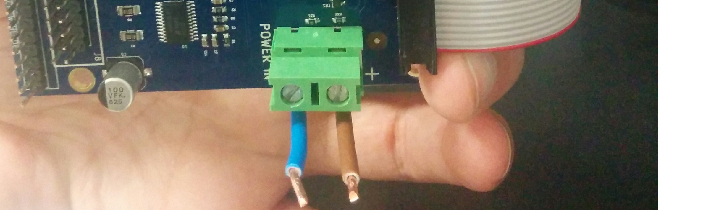
I read through David Crocker's "Converting the RepRapPro Ormerod to Two Colour" webpage but cannot find out how to connect the 12V wires of the duex4 to the 5V power regulator pcb. I have a 0.6 duet board but a 0.2a duex4 expansion board.
Do I just connect the blue and brown wires of the duex4 board directly to the blue and brown wires of the duet board? Or do I need another power regulator pcb?
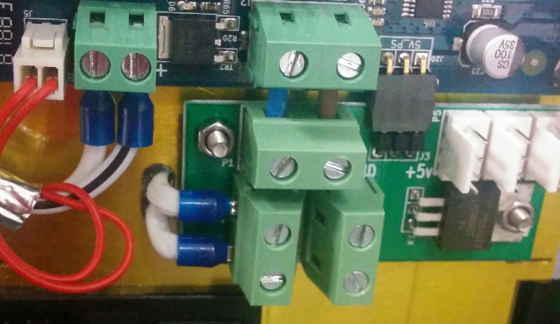
Or can I connect the expansion board to the other screw terminals of the power regulator pcb?
Thank you for your help
I read through David Crocker's "Converting the RepRapPro Ormerod to Two Colour" webpage but cannot find out how to connect the 12V wires of the duex4 to the 5V power regulator pcb. I have a 0.6 duet board but a 0.2a duex4 expansion board.
Do I just connect the blue and brown wires of the duex4 board directly to the blue and brown wires of the duet board? Or do I need another power regulator pcb?
Or can I connect the expansion board to the other screw terminals of the power regulator pcb?
Thank you for your help
|
Re: Duex4 expansion installation problems May 31, 2016 10:04AM |
Registered: 9 years ago Posts: 15 |
Dear Sindex
You will need to install longer wires into your DuetX4, and attach them to the free screw terminals on the 5v Power Regulator PCB.
I've been told that if these are not attached properly, the DuetX4 will try to draw the 12v power through the ribbon cable, which may damage parts of the boards.
Please be cautious about which way around the positive and negative is on the terminals of the 5v regulator. Although it is written on the board, it's not always with reference to which terminal you are looking at.
You can either use a multimeter, or look at the bottom of the 5v regulator board. At the bottom of the board is the "ground plane" and thus all pcb traces connected to this, should be the Negative 12v, hence you may observe which part of which screw terminal is negative, by it's connection to the ground plane.
Best wishes
Mitch
|
Re: Duex4 expansion installation problems May 31, 2016 10:09PM |
Registered: 7 years ago Posts: 3 |
Dear Mitch
Thank you for your reply.
How should I use the multimeter to test for the polarity? Do I compare each free screw terminal with a known ground wire or compare with each other?
The only long wires I have are not solid core wires but with many strands of copper wire is that ok for 12V?
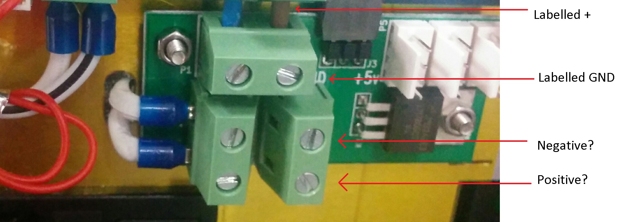
Can you also tell me if my amateur reading of the pcb labeling is correct?
Thank you for your reply.
How should I use the multimeter to test for the polarity? Do I compare each free screw terminal with a known ground wire or compare with each other?
The only long wires I have are not solid core wires but with many strands of copper wire is that ok for 12V?
Can you also tell me if my amateur reading of the pcb labeling is correct?
|
Re: Duex4 expansion installation problems June 01, 2016 04:58AM |
Registered: 9 years ago Posts: 15 |
Dear Sindex
Your reading of the PCB is correct.
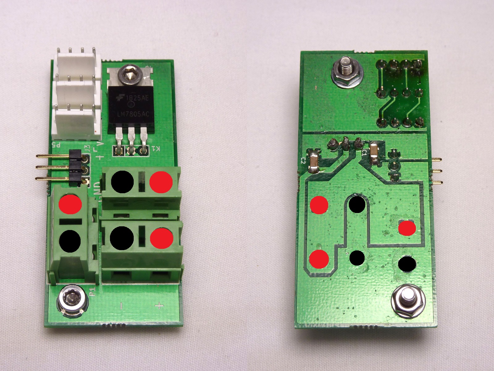
I've attached a color coded image which agrees with your findings, where Black is the GND/Negative and Red is positive, shown by the ground plane connections.
Basically, the terminal on the left side of your image, which is the power input, has negative at the top, which is why the wire has a black stripe when wired correctly, as you have done. This then sets the ground plane.
To test for polarity, you would have to have the power supply on, connect the black wire of your multimeter to the negative side of the 12v, and then probe the various terminals with the red multimeter wire. The multimeter would show 12v where there is +v, and none where there is GND.
It's not necessary for the wire to be single-core. It's only that you must be careful to twist the ends of the wire before putting them into the screw terminals, so that you don't get any frayed wires poking out the side of the terminal, which could cause shorts.
I would recommend using 20AWG or thicker wire, depending on how many motors/heaters you will be installing on the Duetx4.
Edited 1 time(s). Last edit at 06/01/2016 05:01AM by Mitch.
Your reading of the PCB is correct.
I've attached a color coded image which agrees with your findings, where Black is the GND/Negative and Red is positive, shown by the ground plane connections.
Basically, the terminal on the left side of your image, which is the power input, has negative at the top, which is why the wire has a black stripe when wired correctly, as you have done. This then sets the ground plane.
To test for polarity, you would have to have the power supply on, connect the black wire of your multimeter to the negative side of the 12v, and then probe the various terminals with the red multimeter wire. The multimeter would show 12v where there is +v, and none where there is GND.
It's not necessary for the wire to be single-core. It's only that you must be careful to twist the ends of the wire before putting them into the screw terminals, so that you don't get any frayed wires poking out the side of the terminal, which could cause shorts.
I would recommend using 20AWG or thicker wire, depending on how many motors/heaters you will be installing on the Duetx4.
Edited 1 time(s). Last edit at 06/01/2016 05:01AM by Mitch.
|
Re: Duex4 expansion installation problems June 02, 2016 01:41AM |
Registered: 7 years ago Posts: 3 |
Sorry, only registered users may post in this forum.