hot end temperature (fw 0.57a)
Posted by rayhicks
|
hot end temperature (fw 0.57a) January 17, 2014 08:29AM |
Registered: 10 years ago Posts: 578 |
I've just had a go at checking my nozzle temperatures, and it looks like the my thermistor is pretty much spot on up to around 100°C, then starts exaggerating (ie overreading) in the table below, Tr is the temperature read by the duet, Tm is the temperature measured by my thermocouple/multimeter:
This could well be showing a non-linearity in my measurement system, but I have the feeling that it's to do with a beta mismatch or the conversion algorithm - if so then when I need 200°C, I'd need to set something around 220, and for 250 I'd need to set 270-275 (note that the read temperatures end up around +/-5°C away from the set).
The method i used was to insert a small thermocouple into the thermistor mounting hole, snugged up between the aluminium and the thermistor lead insulation so that all items were thermally coupled. The thermocouple was used to indicate the temperature on a Maplin UNI-T UT60E Multimeter. Starting with the heater off, the thermistor showed -2.42 a separate room thermometer showed the ambient to be 19.3 +/0.5, where it stayed for the rest of the run - the thermocouple agreed with a reading of 20°C. I then ramped up the heat setting in steps of 25 or 50°C, waited for the multimeter to indicate an overshoot then fall back to a steady temperature, tabulated this as Tm then sent an M105 command to the duet to get the instantaneous reading from the thermistor (tabulated as Tr).
It isn't the most "pro" thermocouple setup, but it indicates a potential calibration problem - could anyone repeat this with a calibrated thermocouple?
[edit] I'm using a t3p3 duet, maybe this has a different resistor on the board? Also, the bed thermistor agrees with the thermocouple by a couple of degrees over the range 20 - 120 [/edit]
Ray
Edited 2 time(s). Last edit at 01/17/2014 08:35AM by rayhicks.
    Tr   Tm
-2.42    20
25.7     33
51.2     55
72.4     73
99.7    100
150     144
197.3   188
221.9   208
243.1   225
269.3   248
This could well be showing a non-linearity in my measurement system, but I have the feeling that it's to do with a beta mismatch or the conversion algorithm - if so then when I need 200°C, I'd need to set something around 220, and for 250 I'd need to set 270-275 (note that the read temperatures end up around +/-5°C away from the set).
The method i used was to insert a small thermocouple into the thermistor mounting hole, snugged up between the aluminium and the thermistor lead insulation so that all items were thermally coupled. The thermocouple was used to indicate the temperature on a Maplin UNI-T UT60E Multimeter. Starting with the heater off, the thermistor showed -2.42 a separate room thermometer showed the ambient to be 19.3 +/0.5, where it stayed for the rest of the run - the thermocouple agreed with a reading of 20°C. I then ramped up the heat setting in steps of 25 or 50°C, waited for the multimeter to indicate an overshoot then fall back to a steady temperature, tabulated this as Tm then sent an M105 command to the duet to get the instantaneous reading from the thermistor (tabulated as Tr).
It isn't the most "pro" thermocouple setup, but it indicates a potential calibration problem - could anyone repeat this with a calibrated thermocouple?
[edit] I'm using a t3p3 duet, maybe this has a different resistor on the board? Also, the bed thermistor agrees with the thermocouple by a couple of degrees over the range 20 - 120 [/edit]
Ray
Edited 2 time(s). Last edit at 01/17/2014 08:35AM by rayhicks.
|
Re: hot end temperature (fw 0.57a) January 17, 2014 09:28AM |
Registered: 10 years ago Posts: 14,672 |
I'm not too surprised by your results, for two reasons:
1. The datasheet for the thermistor from the manufacturer (Honeywell) is very poor, all it gives is dimensions, nominal resistance (100K) and resistance tolerance (+/- 2%). Their catalog also gives "Resistance ratio" but doesn't appear to define that term. The thermistor beta value quoted by Digikey will be measured over a particular temperature range, which Digikey implies is 0 to 50C. Likewise, there will be a tolerance on the beta value, which Digikey say is +/- 2.1%, but with no visible supporting evidence from Honeywell.
2. The Duet firmware doesn't use the full Steinhart–Hart equation, it uses the simpler beta-equation, which is essentially the Steinhart–Hart equation with the c term set to zero. The further you are away from the calibration temperature (25C in this case), the more important the c term becomes.
Large delta printer [miscsolutions.wordpress.com], E3D tool changer, Robotdigg SCARA printer, Crane Quad and Ormerod
Disclosure: I design Duet electronics and work on RepRapFirmware, [duet3d.com].
|
Re: hot end temperature (fw 0.57a) January 17, 2014 09:55AM |
Registered: 10 years ago Posts: 578 |
@ dc42 With those tolerances, it's surprisingly good  - curve fitting my data from 100°C upwards in excel gives me an intercept of 13.45 and a slope of 0.87 with a very good r^2 (0.9995) - perhaps a gcode or two could be given up to (optionally) calibrating the response on a particular system using such a fit? Though calbration would need to be done for each thermistor and would require the user to have a means of reliable temperature measurement, so may not be worth the effort (which may be better spent on designing a thermocouple interface to replace the thermistor).
- curve fitting my data from 100°C upwards in excel gives me an intercept of 13.45 and a slope of 0.87 with a very good r^2 (0.9995) - perhaps a gcode or two could be given up to (optionally) calibrating the response on a particular system using such a fit? Though calbration would need to be done for each thermistor and would require the user to have a means of reliable temperature measurement, so may not be worth the effort (which may be better spent on designing a thermocouple interface to replace the thermistor).
|
Re: hot end temperature (fw 0.57a) January 17, 2014 10:09AM |
Registered: 10 years ago Posts: 2,472 |
Yay! my replacement Duet arrived this morning - thanks RRP. I can of course no longer look at the temperatures the old board was reporting, and this board is reading differently judging by how quickly it reaches the set temperature and the fact that the bed and extruder temperatures are both only a few degrees out at room temperature (the previous board reported temperatures below freezing). The old board could not get to a bed temperature of 110 deg at all, this board reports it reaches that temperature in about 10 to 15 minutes. The old board struggled to get the extruder up to 240 degrees - this one reports it has got there in a few minutes. So I'm pretty certain that my old board was grossly under-reading - bear in mind nothing else significant has been changed.
Having said that, the first thing I did with the new Duet was to load the latest firmware. I don't know if there have been changes to the temperature reading algorithms between the firmware downloaded this morning (ver 057a of 16 Jan) and the firmware in my old board (version of 06 Jan). The Z IR sensor is now reading far lower - so much so that it is unusable for Z homing in my black housing and I'll be changing the LED resistor to increase its brightness. Again, this could be a difference in the board hardware, or a change to that part of the firmware may have been made. With the Z height above 10mm, the reading is 1 or 2. The reading at 1mm extruder height above my white paper measuring spot is just 6. At 0 height it reads 97. The homing tab (covered in silver foil) reads 450 with the IR sensor directly above it, so it's still good for X homing. I checked that there is 3.3V on the sensor board, and double-checked the photo diode output goes to the correct pin on the Duet board. I could regress the board to the previous firmware to see the difference I suppose, but I'm ready to crack on with other things now, so probably won't do so.
OK - temperatures on this board/firmware seem pretty accurate. Clamping the thermocouple under the glass with some white expanded foam (the PSU packing material) over the glass for insulation settles to a quite wide measured temperature cycle between 97 to 109 when the bed is set to 110. Pronterface reports a cycle of 102 to 114, so a tad optimistic - though of course my probe is above the aluminium and the Ormerod probe is better buried. Setting a bed temperature of 65 causes the meter to cycle between 57 and 62.
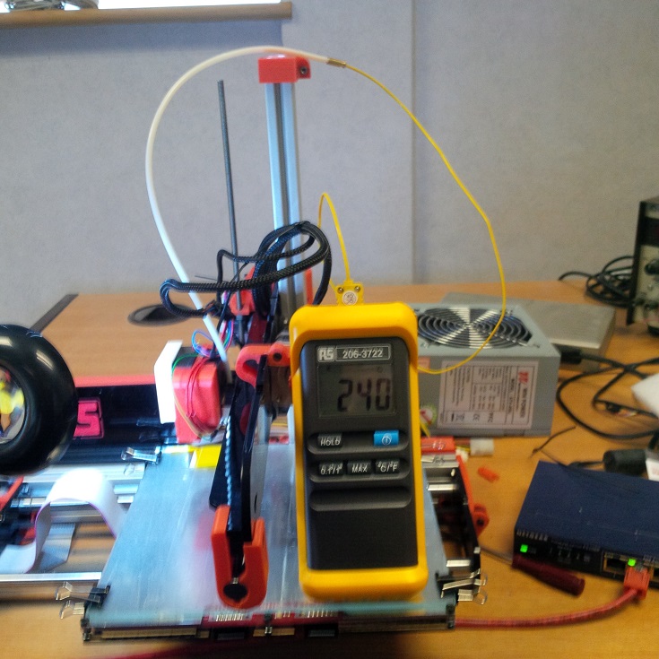
The extruder temperature is great. I took out the filament and fed the thermocouple down the bowden cable till it bottomed in the nozzle, presumably immersed in the remnants of molten plastic. Setting a temperature of 240 resuted in Pronterface reporting a cycle between about 233 and 239 (it never got to a reported temp of 240). However the thermocouple reported a rock-steady 240 degrees in the nozzle - the meter display did not change over the 5 minutes I was measuring (see photo - bit of camera shake, sorry). Setting to 250 got the thermometer reading switching steadily between 249 and 250 within about 30 seconds, and setting 200 degrees resulted in 201 holding pretty steady on the meter.
The thermocouple tip did end up with a plastic coating, but it peeled off easily. With the extruder left at 250 degrees for about 30 minutes (but a cold bed), pressing the thermocouple hard against the top aluminium cooling block on the extruder resulted in a reading of 37 degrees.
Dave
(#106)
So I'm happy that the temperatures are accurate enough in the rage of interest.
Having said that, the first thing I did with the new Duet was to load the latest firmware. I don't know if there have been changes to the temperature reading algorithms between the firmware downloaded this morning (ver 057a of 16 Jan) and the firmware in my old board (version of 06 Jan). The Z IR sensor is now reading far lower - so much so that it is unusable for Z homing in my black housing and I'll be changing the LED resistor to increase its brightness. Again, this could be a difference in the board hardware, or a change to that part of the firmware may have been made. With the Z height above 10mm, the reading is 1 or 2. The reading at 1mm extruder height above my white paper measuring spot is just 6. At 0 height it reads 97. The homing tab (covered in silver foil) reads 450 with the IR sensor directly above it, so it's still good for X homing. I checked that there is 3.3V on the sensor board, and double-checked the photo diode output goes to the correct pin on the Duet board. I could regress the board to the previous firmware to see the difference I suppose, but I'm ready to crack on with other things now, so probably won't do so.
OK - temperatures on this board/firmware seem pretty accurate. Clamping the thermocouple under the glass with some white expanded foam (the PSU packing material) over the glass for insulation settles to a quite wide measured temperature cycle between 97 to 109 when the bed is set to 110. Pronterface reports a cycle of 102 to 114, so a tad optimistic - though of course my probe is above the aluminium and the Ormerod probe is better buried. Setting a bed temperature of 65 causes the meter to cycle between 57 and 62.
The extruder temperature is great. I took out the filament and fed the thermocouple down the bowden cable till it bottomed in the nozzle, presumably immersed in the remnants of molten plastic. Setting a temperature of 240 resuted in Pronterface reporting a cycle between about 233 and 239 (it never got to a reported temp of 240). However the thermocouple reported a rock-steady 240 degrees in the nozzle - the meter display did not change over the 5 minutes I was measuring (see photo - bit of camera shake, sorry). Setting to 250 got the thermometer reading switching steadily between 249 and 250 within about 30 seconds, and setting 200 degrees resulted in 201 holding pretty steady on the meter.
The thermocouple tip did end up with a plastic coating, but it peeled off easily. With the extruder left at 250 degrees for about 30 minutes (but a cold bed), pressing the thermocouple hard against the top aluminium cooling block on the extruder resulted in a reading of 37 degrees.
Dave
(#106)
So I'm happy that the temperatures are accurate enough in the rage of interest.
|
Re: hot end temperature (fw 0.57a) January 17, 2014 10:22AM |
Registered: 10 years ago Posts: 578 |
@dmould - that's very encouraging, I'll try passing mine down the bowden, maybe it was cooled by surrounding air in the method I used, which would have more effect at higher temperatures. I think that the thermistor code has changed since the 6th Jan release (I've been using one of dc42's test builds until today, which also had the code in, but thought I'd try the measurement on the 0.57a release when I flashed it this morning).
Glad to hear you're up and running again!
Ray
Glad to hear you're up and running again!
Ray
|
Re: hot end temperature (fw 0.57a) January 17, 2014 10:44AM |
Registered: 10 years ago Posts: 14,672 |
Hi dmould,
Yes the thermistor reading code has changed. The old code under-reported the extruder temp at low temperatures and over-read it at high temperatures. However, the code for reading the IR sensor has not changed at all. Perhaps your sensor has shifted position, or the connector is coming loose? The screw holes in it allow for quite a lot of movement.
Large delta printer [miscsolutions.wordpress.com], E3D tool changer, Robotdigg SCARA printer, Crane Quad and Ormerod
Disclosure: I design Duet electronics and work on RepRapFirmware, [duet3d.com].
|
Re: hot end temperature (fw 0.57a) January 17, 2014 11:04AM |
Registered: 10 years ago Posts: 2,472 |
Quote
dc42
Hi dmould,
Yes the thermistor reading code has changed. The old code under-reported the extruder temp at low temperatures and over-read it at high temperatures. However, the code for reading the IR sensor has not changed at all. Perhaps your sensor has shifted position, or the connector is coming loose? The screw holes in it allow for quite a lot of movement.
It is up as high as possible in its little cubby, just as I mounted it, and no dirt or foreign bodies obscuring it. I can probe the 3 pins with the Duet powered. I get 3.3V between the centre (black wire) and the pin closest to the extruder (red wire). Between the centre and sensor (blue wire) pin I get a reading of 0.09V with nothing under the sensor. Holding a bit of white paper against the sensor opening results in a reading of 1.9V. removing the blue wire from the Duet board makes no difference to those readings. I'm about to remove the board now to check further.
|
Re: hot end temperature (fw 0.57a) January 17, 2014 12:26PM |
Registered: 10 years ago Posts: 2,472 |
OK, I think I've diagnosed the fault. It seems that the short to 12V did more than damage just the Duet. I already knew that it had blown my SD card (I replaced it). I think it also overloaded the IR emitter of the Z sensor. The phototransistor seems to still work and my phone's camera shows an IR output from the LED, but I think it is a lot weaker than it should be (difficult to tell as I have nothing to compare it with). Looking at the TCRT1000 spec, 12V on the 3.3V rail should not have damaged the phototransistor, but would have exceeded the max forward current of the IR emitter. I'll replace the device next week, but meanwhile I've changed the 150 ohm series resistor to a 51 ohm part (still within the 50mA max), which has improved things significantly.
Sorry, only registered users may post in this forum.