Power supply problems solved
Posted by DennisCowdery
|
Power supply problems solved January 03, 2014 08:55AM |
Registered: 10 years ago Posts: 31 |
My Omerod #343 has been plagued with software crashes caused by power transients.
Thanks to detective work by people on this forum I have been able to identify the underlying problems and corrected the hardware design.
Much work was done to cure the effects of these transients (V.Good), but I have gone for the source. If the unit generates enough interference to trip itself then this is wrong! and would not meet EMC regulations.
1) The bed heater is a parallel tuned circuit with L=2.2uH, R=1.16ohms and Cstray variable with cable lay. This is a reality of its nature, not a fault.
2) The transient impeadance of the 12V psu is indeterminate particularly upswings which it would not encounter in normal use. The leads add series inductance and ther is little decoupling on the PCB for this.
3) The bed driver FET turns on in about 2us and off on about 15ns.
Cumulative result - Parasitic oscillations of +/- 20-40V on the 12V line and heater wires - this noise WILL get everywhere (25ns period) and disturb downs stream regulators - not suprisingly!!
FIX- a) 4700uf cap + 10uf tant on 12Vinput to pcb. b)1000uF 16vcap on C3. c)include an 180ohm resistor in series with the gate of TR2 fet.
d) wire a 1A 30v (piv) schottkey diode across the heater bed -observe direction!!
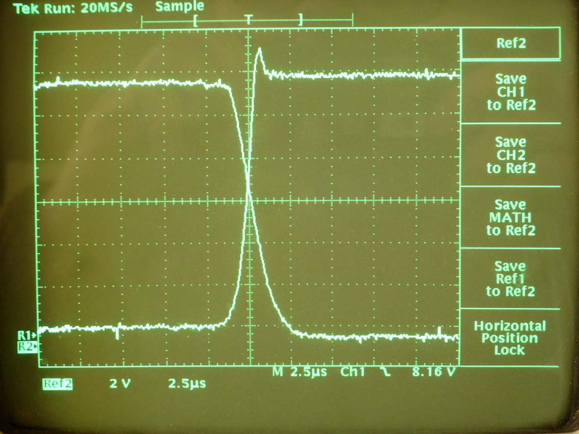
These will give the switching transients shown in the attached pictures.
THESE MODS ARE NOT FOR CLUBTHUMBS! (apart fom invalidating the warranty)
Soon I hope to lay plastic!
Dennis Cowdery
Thanks to detective work by people on this forum I have been able to identify the underlying problems and corrected the hardware design.
Much work was done to cure the effects of these transients (V.Good), but I have gone for the source. If the unit generates enough interference to trip itself then this is wrong! and would not meet EMC regulations.
1) The bed heater is a parallel tuned circuit with L=2.2uH, R=1.16ohms and Cstray variable with cable lay. This is a reality of its nature, not a fault.
2) The transient impeadance of the 12V psu is indeterminate particularly upswings which it would not encounter in normal use. The leads add series inductance and ther is little decoupling on the PCB for this.
3) The bed driver FET turns on in about 2us and off on about 15ns.
Cumulative result - Parasitic oscillations of +/- 20-40V on the 12V line and heater wires - this noise WILL get everywhere (25ns period) and disturb downs stream regulators - not suprisingly!!
FIX- a) 4700uf cap + 10uf tant on 12Vinput to pcb. b)1000uF 16vcap on C3. c)include an 180ohm resistor in series with the gate of TR2 fet.
d) wire a 1A 30v (piv) schottkey diode across the heater bed -observe direction!!
These will give the switching transients shown in the attached pictures.
THESE MODS ARE NOT FOR CLUBTHUMBS! (apart fom invalidating the warranty)
Soon I hope to lay plastic!
Dennis Cowdery
|
Re: Power supply problems solved January 03, 2014 09:27AM |
Registered: 10 years ago Posts: 14,672 |
Very neatly done!
I think the capacitor between source and drain used by Radian is also a good (and easier) alternative to the gate resistor, given that the mosfet turn-on is so slow, although personally I would try 0.47uF rather than 1uF. I added only a 1uF decoupling capacitor, and that seems to be sufficient for my board - there is another 400uF not too far away on the board already, and 1uF fits easily underneath the board.
Large delta printer [miscsolutions.wordpress.com], E3D tool changer, Robotdigg SCARA printer, Crane Quad and Ormerod
Disclosure: I design Duet electronics and work on RepRapFirmware, [duet3d.com].
|
Re: Power supply problems solved January 03, 2014 12:23PM |
Registered: 10 years ago Posts: 300 |
Hi Dennis, one concern I have with using a diode to quench the back-EMF is the current it has to handle. There's about 250uJ stored in the Bed and it's released in a couple of uS. Isn't that around 10A peak? If the diode fails, it will almost certainly go short and may then cause some real grief. Suppression Capacitors are designed to fail O/C and take this kind of thing in their stride.
BTW, don't forget the Extruder Heater transistor - this switches around 4 to 5A and is placed in a much more critical position on the PCB. I don't know about dc42, but my Ormorod was locking-up during most prints before I fixed the back-EMF on both heaters.
RS Components Reprap Ormerod No. 481
BTW, don't forget the Extruder Heater transistor - this switches around 4 to 5A and is placed in a much more critical position on the PCB. I don't know about dc42, but my Ormorod was locking-up during most prints before I fixed the back-EMF on both heaters.
RS Components Reprap Ormerod No. 481
|
Re: Power supply problems solved January 03, 2014 01:04PM |
Registered: 10 years ago Posts: 14,672 |
Hmm... there seems to be some disagreement on the amount of energy stored in the bed heater inductance. I estimated 40uJ based on the length of time that the mosfet is avalanching. You say 250uJ. Dennis says the inductance is 2.2uH, which at 10A gives 110uJ.
I don't know which 1A Schottky diode Dennis is using, but rectifier diodes usually have a surge current rating well above the RMS rating. For example, the 1N5818 1A diode has a surge rating of 25A for 8.3ms, so 10A for a microsecond should be no problem. I don't think a flyback diode is really necessary if you use either a source-drain capacitor or series gate resistor to slow down the turn off, although it will probably reduce the emissions.
Large delta printer [miscsolutions.wordpress.com], E3D tool changer, Robotdigg SCARA printer, Crane Quad and Ormerod
Disclosure: I design Duet electronics and work on RepRapFirmware, [duet3d.com].
|
Re: Power supply problems solved January 03, 2014 01:30PM |
Registered: 10 years ago Posts: 41 |
I saw this post on a blog about a Mendal 90
[hydraraptor.blogspot.co.uk]
The interesting bit for PSU info is that the PSU used in this kit looks the same as the Ormerod one
and it says
"I also changed the PSU to an ATX500 because I can buy them in the UK with CE approval and they come with integral mains inlet and switch, obviating the need for the kit builder to do their own mains wiring. It is also shorter, allowing room for the Melzi (which is very long and thin). The downside is it needs a pair of load resistors on the 5V and 3.3V to get the 12V rail to be close to 12V under load. These are provided in the kit."
I have noticed that the 12 volts drops to about 11.5 when the bed is on
I wonder if drawing something from the 5/3.3 rails would improve this regulation.
Chris
|
Re: Power supply problems solved January 03, 2014 01:37PM |
Registered: 10 years ago Posts: 14,672 |
I believe that putting a load on the +5V and/or +3.3V rails would increase the voltage on the 12V supply, but I'm not at all sure it would improve the regulation. I don't think the poor 12V regulation is a problem anyway, at least when printing with PLA. The real problem is that the bed heater and extruder heater driver electronics produce a lot of electrical noise, which the current Duet board design does not mitigate adequately.
Large delta printer [miscsolutions.wordpress.com], E3D tool changer, Robotdigg SCARA printer, Crane Quad and Ormerod
Disclosure: I design Duet electronics and work on RepRapFirmware, [duet3d.com].
Large delta printer [miscsolutions.wordpress.com], E3D tool changer, Robotdigg SCARA printer, Crane Quad and Ormerod
Disclosure: I design Duet electronics and work on RepRapFirmware, [duet3d.com].
|
Re: Power supply problems solved January 03, 2014 01:44PM |
Registered: 10 years ago Posts: 300 |
@dc42
I was working with 3.5uH as the bed plus cable inductance (which I had measured with an LCR meter) and 12A which my 25A bench supply indicated.
BTW, Basics_about_switching_loads_with_MOSFETs on the reprap.org site discusses the use of a freewheeling diode and laments its absence on a number of printer controllers! The article seems to be more concerned for the health and safety of the MOSFET but my experience tells me it's crucial to the stable operation of the entire printer.
Edited 1 time(s). Last edit at 01/03/2014 02:08PM by Radian.
RS Components Reprap Ormerod No. 481
|
Re: Power supply problems solved January 03, 2014 02:07PM |
Registered: 10 years ago Posts: 300 |
Quote
DennisCowdery
d) wire a 1A 30v (piv) schottkey diode across the heater bed -observe direction!!
Hi Dennis, do you have a way to post up a scope trace of the Drain voltage and the 12V PSU using the diode? Just curious to compare it with the capacitor snubber. I'm being a bit lazy now, as I could do it myslef but I've lost count of the number of times I've pulled the Duet PCB out to tinker.
RS Components Reprap Ormerod No. 481
|
Re: Power supply problems solved January 03, 2014 04:06PM |
Registered: 10 years ago Posts: 314 |
The power board does have 22R and 30R resistors on the lower side (probably obscured by the wiring loom). I presume these are the loads for the other supplies.Quote
chriscain
I saw this post on a blog about a Mendal 90
[hydraraptor.blogspot.co.uk]
The interesting bit for PSU info is that the PSU used in this kit looks the same as the Ormerod one
and it says
"I also changed the PSU to an ATX500 because I can buy them in the UK with CE approval and they come with integral mains inlet and switch, obviating the need for the kit builder to do their own mains wiring. It is also shorter, allowing room for the Melzi (which is very long and thin). The downside is it needs a pair of load resistors on the 5V and 3.3V to get the 12V rail to be close to 12V under load. These are provided in the kit."
I have noticed that the 12 volts drops to about 11.5 when the bed is on
I wonder if drawing something from the 5/3.3 rails would improve this regulation.
Chris
|
Re: Power supply problems solved January 03, 2014 04:51PM |
Registered: 10 years ago Posts: 135 |
|
Re: Power supply problems solved January 03, 2014 06:01PM |
Admin Registered: 17 years ago Posts: 7,879 |
I use 10R and 4R7, so yes, they are a lot higher. ACE 500W and ALPINE 500W both work fine on Mendel90 with the same type of bed but Melzi electronics, not Duet.
Edited 1 time(s). Last edit at 01/03/2014 07:25PM by nophead.
[www.hydraraptor.blogspot.com]
Edited 1 time(s). Last edit at 01/03/2014 07:25PM by nophead.
[www.hydraraptor.blogspot.com]
|
Re: Power supply problems solved January 04, 2014 10:50AM |
Registered: 10 years ago Posts: 31 |
Hi Radian,
Clearly you have done a lot of good work on the hardware and know your business!
The diode I used was an 1N5818, but as it was only asked to absorb this energy dump every 30 secs or so then I reckoned this to be ok.
The current in the diode depends on the resistance of the heater amongst other things, and I reckoned it would handle 10 amps for a few microsecs.
I previously tried conventional snubber networks but these only seemed to move the frequency down the frequency band, so I went for the full nuke!
The diode fits well in the spare holes in the PCB.
For my particular unit that seems to conclude hardware issues, but the bed of my unit is twisted and flimsy, and I am not happy with it
The twist is spherical without the glass and variable with it - NBG at all. This is the next engineering task. I have yet to lay plastic.
Do you know how people fitted the slugging capacitor to their FETS??. The should use the Miller capacitance of the device (increase it by a few 100 pf) but you still need a few ohms in the gate line to stop the driver FET from being loaded by it.
I have seen values of 1uF mentioned. If people are putting this across their FET then they will put a big transient load on the FET on turn on (I have popped them in the past this way), they will also inject current into the PCB- anyway my method works for me.
Keep up the good work
Dennis Cowdery
|
Re: Power supply problems solved January 04, 2014 10:55AM |
Registered: 10 years ago Posts: 31 |
|
Re: Power supply problems solved January 04, 2014 10:57AM |
Registered: 10 years ago Posts: 31 |
|
Re: Power supply problems solved January 04, 2014 10:59AM |
Registered: 10 years ago Posts: 31 |
|
Re: Power supply problems solved January 04, 2014 11:04AM |
Registered: 10 years ago Posts: 14,672 |
Hi Dennis,
I was initially horrified when I heard of a 1uF capacitor being connected across the FET. However, the turn on time of the FET is quite slow because the gate is charging through a 1K resistor. The slew rate I measured was 6V/us (with no capacitor). This gives a peak discharge current from the 1uF capacitor of 6A (even if the slew rate is maintained after adding the capacitor), which is somewhat less than the bed current. I still find this a little high, so if I were doing this mod, I would use a smaller capacitor, perhaps 0.47uF. But I have a 100 ohm gate resistor now, which slows down the turn-off sufficiently - although I think 200 ohms would be even better.
I had previously suggested, but not tried a Schottky diode-resistor-capacitor arrangement: diode cathode to capacitor, anode to mosfet drain, other side of capacitor to ground (as close to mosfet source as possible), and resistor in parallel with the diode. Then the capacitor discharges through the resistor at turn-on, and charges through the diode at turn-off.
Edited 2 time(s). Last edit at 01/04/2014 11:06AM by dc42.
Large delta printer [miscsolutions.wordpress.com], E3D tool changer, Robotdigg SCARA printer, Crane Quad and Ormerod
Disclosure: I design Duet electronics and work on RepRapFirmware, [duet3d.com].
Quote
DennisCowdery
I have seen values of 1uF mentioned. If people are putting this across their FET then they will put a big transient load on the FET on turn on (I have popped them in the past this way), they will also inject current into the PCB
I was initially horrified when I heard of a 1uF capacitor being connected across the FET. However, the turn on time of the FET is quite slow because the gate is charging through a 1K resistor. The slew rate I measured was 6V/us (with no capacitor). This gives a peak discharge current from the 1uF capacitor of 6A (even if the slew rate is maintained after adding the capacitor), which is somewhat less than the bed current. I still find this a little high, so if I were doing this mod, I would use a smaller capacitor, perhaps 0.47uF. But I have a 100 ohm gate resistor now, which slows down the turn-off sufficiently - although I think 200 ohms would be even better.
I had previously suggested, but not tried a Schottky diode-resistor-capacitor arrangement: diode cathode to capacitor, anode to mosfet drain, other side of capacitor to ground (as close to mosfet source as possible), and resistor in parallel with the diode. Then the capacitor discharges through the resistor at turn-on, and charges through the diode at turn-off.
Edited 2 time(s). Last edit at 01/04/2014 11:06AM by dc42.
Large delta printer [miscsolutions.wordpress.com], E3D tool changer, Robotdigg SCARA printer, Crane Quad and Ormerod
Disclosure: I design Duet electronics and work on RepRapFirmware, [duet3d.com].
|
Re: Power supply problems solved January 04, 2014 01:11PM |
Registered: 10 years ago Posts: 300 |
Just to add that I've started a dedicated thread to discuss the Heater switching transients issue.
RS Components Reprap Ormerod No. 481
RS Components Reprap Ormerod No. 481
Sorry, only registered users may post in this forum.