Ormerod from RS
Posted by ROBBED666
|
Re: Ormerod from RS December 12, 2013 06:11AM |
Registered: 10 years ago Posts: 314 |
|
Re: Ormerod from RS December 12, 2013 08:44AM |
Registered: 10 years ago Posts: 7 |
@Ian,
Yes indeed you did answer my question and more! It's very much appreciated and gives me a good insight into how the X-carriage and print-head were designed to work together.
I also understand that when in printing pre-determined compensation is applied to the head positioning to ensure any alignment corrections are accounted for. This alays any concern I had over observing the X-axis arm not being perpendicular to the Y-axis movement. Am I then right to believe this method of correction will cater for the print head, when moved along it's axis close to the heated-table, is not moving exactly parallel to the table surface. It can be lowered to touch the table at the X-motor end of its movement and arrive about 2.5mm above the table top at it's furthest position from the X-motor?
As for the Z-runner mount, I did set this up with the bearings gripping the vertical extruded ali' column firmly and find no play in the X-arm, it is rock solid yet travels freely up and down the column albeit through manually rotating the lead screw (not hooked up power, etc. yet) that drives the Z-movement. It may be that my way of getting this tightly fitting originally could have led to the lack of perpendicularity between the Y-movement and X-movment along the arm!
Thanks again Ian.
Graham.
|
Re: Ormerod from RS December 12, 2013 12:01PM |
Registered: 10 years ago Posts: 9 |
@Ray Hicks
You are quite right. I crossed my wires on R numbers.
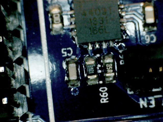
However I am now convinced that R60 and 61 are mounted incorrectly. I can see the silk screen markers underneath at 90 degrees to the Rs.
Clearly this will f$£%-up the A4403 s operation.
I am awaiting Ian's permission to remove and remount these correctly so they will conform to the layout drawing.
Only then will we know if the ic survives.
I recommend anyone else with electric trouble to look at these Rs and all components on Duet and check orientation against either/both the silk screen or diagram.
I assume this SM board had robotic component placement so I can't imagine that mine is the only one with exactly this mistake???
Edited 1 time(s). Last edit at 12/12/2013 12:03PM by pault.
You are quite right. I crossed my wires on R numbers.
However I am now convinced that R60 and 61 are mounted incorrectly. I can see the silk screen markers underneath at 90 degrees to the Rs.
Clearly this will f$£%-up the A4403 s operation.
I am awaiting Ian's permission to remove and remount these correctly so they will conform to the layout drawing.
Only then will we know if the ic survives.
I recommend anyone else with electric trouble to look at these Rs and all components on Duet and check orientation against either/both the silk screen or diagram.
I assume this SM board had robotic component placement so I can't imagine that mine is the only one with exactly this mistake???
Edited 1 time(s). Last edit at 12/12/2013 12:03PM by pault.
|
Re: Ormerod from RS December 12, 2013 01:25PM |
Registered: 12 years ago Posts: 1,236 |
Quote
pault
@Ray Hicks
You are quite right. I crossed my wires on R numbers.
However I am now convinced that R60 and 61 are mounted incorrectly. I can see the silk screen markers underneath at 90 degrees to the Rs.
I think you are on to something, if you look at the image from T3P3 blog it shows those resistors parallel to C5. However, the board layout in github, Duet0.6 shows them NOT parallel.

So either something changed without revision number update or they are not mounted correctly.
Seems an unlikely error for a SM machine, but it wouldn't be unknown for early production samples to be hand mounted...
Edited 3 time(s). Last edit at 12/12/2013 01:31PM by bobc.
What is Open Source?
What is Open Source Hardware?
Open Source in a nutshell: the Four Freedoms
CC BY-NC is not an Open Source license
|
Re: Ormerod from RS December 12, 2013 01:59PM |
Registered: 10 years ago Posts: 578 |
@pault and bobc - I see what you mean, I've attached a picture of my circuit board I took last night, which shows the screen printed outlines running across the resistors, presumably R60 is connected across pads common to both outlines, accounting for the short. This hypothesis would be backed up by the fact that there's a track running from pin 5 ( FB ) of the A4403 to the upper pad of R60.)and this would intentionally be the commoning point)
Ray
Edited 1 time(s). Last edit at 12/12/2013 02:00PM by rayhicks.
Ray
Edited 1 time(s). Last edit at 12/12/2013 02:00PM by rayhicks.
|
Re: Ormerod from RS December 12, 2013 02:49PM |
Registered: 12 years ago Posts: 1,236 |
Here is a screenshot of the board layout I see in github [github.com]
I am fairly certain there is an assembly error.
Edited 1 time(s). Last edit at 12/12/2013 02:50PM by bobc.
What is Open Source?
What is Open Source Hardware?
Open Source in a nutshell: the Four Freedoms
CC BY-NC is not an Open Source license

I am fairly certain there is an assembly error.
Edited 1 time(s). Last edit at 12/12/2013 02:50PM by bobc.
What is Open Source?
What is Open Source Hardware?
Open Source in a nutshell: the Four Freedoms
CC BY-NC is not an Open Source license
|
Re: Ormerod from RS December 12, 2013 03:27PM |
Registered: 10 years ago Posts: 578 |
that nails it for me: R60 is shorted across on my board as observed before - I've just checked continuity of the pads that R61 sits on - the top pad (in situ on the machine, but labelled GND 1 in the overlay) is short to GND, the bottom (on the left in the overlay and labelled 2 +5V) is short to +5V, I'd say those two resistors are definitely rotated 90° as pault surmised, with R61 linking the GND and +5V nets and R60 sitting on top of a floating feedback input track
Ray
Ray
|
Re: Ormerod from RS December 12, 2013 03:36PM |
Registered: 10 years ago Posts: 314 |
Hi All,
Good detective work re component orientation, I have the same 'wrong' layout, so assume that's how they were all produced.
The good news is I don't think there should be any damage as it means the feedback pin is floating (hence no output or wrong voltage) and one of the resistors is just across the 5V supply, so there should be no problem. I expect both will be replaced when repaired.
I am going to continue with JP9 removed and use the USB for now.
@ALL, thanks for the help in getting me off the ground, but I have a couple more questions and comments.
The Arduino serial interface works and returns the following:
serial: M503
; RepRapPro Ormerod
; Standard configuration G Codes
M111 S1; Debug on
M550 POrmerod; Set the machine's name
M551 Preprap; Set the password
M552 P192.168.1.14; Set the IP address
M553 P255.255.255.0; Set netmask
M554 P192.168.1.1; Set the gateway
M555 P2; Emulate Marlin USB output
M92 E420; Set extruder steps/mm
G21 ; Work in mm
G90 ; Absolute positioning
M83 ; Extrusions relative
M558 P1 ; Turn Z Probe on
G31 Z0.5 P500 ; Set Z probe height and threshold
M906 X800 Y800 Z800 E800 ; Motor currents (mA)
T0 ; Select extruder 0
I have installed Chrome, but using IP 192.168.1.14 still does not give any response.
I have installed the latest SD download onto a new microSDHC, but this behaves as the supplied one.
With the network lead connected (tried two) when I power up the DUET via the USB the green led flashes at different rates, eventually slowing down and staying on. No activity is seen regarding the orange LED.
Is there anything I need to set in Chrome?
As Pronterface seems to now connect via the USB, I shall power up the 550W supply and see how far I get tomorrow, but again any pointer prior to this big step gratefully received!
|
Re: Ormerod from RS December 12, 2013 03:52PM |
Registered: 12 years ago Posts: 1,611 |
pault - excellent investigative work.
We have been investigating this problem ourselves, and came to the same conclusion a couple of days ago, with the help of the manufacturer - the boards are made in the UK, so at least it got fixed quickly. Unfortunately, it seems a manufacturing issue has caused the first 200 kits to be shipped with the same problem, and it's taken us a day or two to restock fixed Duets, and formulate a plan to replace so many sets of electronics with RS. I should stress that the Duets DO work; it's just that the USB connection does have to be connected to supply 5V to the logic. Early Duet boards that we had did not have this problem, so we didn't pick it up until customers, such as yourselves, started commenting on it.
Sorry for the inconvenience. Unfortunately, moving to a completely new set of electronics, with new firmware, was always going to have the odd hiccup. I'd much prefer this hadn't happened; it certainly has made support a bit of a headache! Any other issues, eg ethernet not working like Markus's Duet, are not related - these sorts of issues will require a normal warranty replacement, which has already been organised in his case.
Here is our official statement, which I will post in a separate thread in this sub-forum; if you contact RS, you should get the same response. Hopefully, they're going to handle the admin on this one!
=========================================================
RepRapPro Ormerod - Duet controller, USB connection and power
The instructions for Ormerod state that the machine has to have its USB lead connected, even when it is being controlled by its network/ethernet/web interface (and so not via the USB ). The reason for this is that the USB is required to supply 5 volts power to the board.
This is not ideal because it ties up the computer on the other end of the USB which - if it is a laptop - it might be useful to take away while a 3D print is being done to do other work. (In fact, the Duet will also work if it is plugged into a powered USB hub if one is available, in which case the computer would not be required.)
Ormerods and Duet boards supplied after 10 December do not suffer this restriction. They will work over the ethernet just under power from the Ormerod itself.
If they wish, buyers of the initial 220 machines with the restriction can get a free upgrade from RepRapPro Ltd. They will need to return their Duet board to:
RepRapPro Ltd
House 6, Unit 7,
Great Leaze Farm,
Oldbury on Severn
BS35 1RF
UK
together with a return address label, a note giving the price paid for postage, and an e-mail address to which the postage can be refunded via Paypal. The Duet should be packaged in its original anti-static packaging inside a padded envelope. The outside of the envelope should have a "Fragile - handle with care" label on.
==========================================================
@pault - If you are confident in your skills to fix your board, go for it. I'd prefer it if you returned the board, as returned boards will be sent back to the manufacturer for fixing; you may be left with a dud board that we can't resurrect either.
There is another fix to get 5V on the board, not via USB, which is to put 3 x pin headers on the board next to the 12V power input. There is a 5V line input here, and the ATX power PCB has a similar 3-pin header on it. Make a jumper wire to connect the two, though I'm not sure of the pinout. This can supply 5V power. The third pin (can't remember the order) can control the ATX PSU, turning it on and off. We hope to include this functionality in a future version of the firmware.
I'll copy all of the above to a new thread. Please feel free to ask me any questions regarding this, in the new thread. If others want to copy their investigation work and responses there, it may help people to be better informed, and reduce the diverse topics covered in this thread.
Ian
RepRapPro tech support
Edited 2 time(s). Last edit at 12/12/2013 03:54PM by droftarts.
|
Re: Ormerod from RS December 12, 2013 04:17PM |
Registered: 12 years ago Posts: 1,611 |
|
Re: Ormerod from RS December 12, 2013 04:32PM |
Registered: 10 years ago Posts: 314 |
The monster lives!
Now have x,y and z operational from Pronterface.
Y and Z home also work, but X home doesn't tell the stepper motor to drive (but the step functions do!)
But another step in the right direction.......
Advice as mentioned on earlier post on Chrome/ network connection is still of interest.
I did find the X axis clashed with the electronics enclosure when Z was a low height and if I move the enclosure one of the T nuts will no longer be in a slot! I did check my dimensions at build time but will investigate tomorrow. Anyone else found this?
Edited 2 time(s). Last edit at 12/12/2013 04:36PM by Treth.
|
Re: Ormerod from RS December 12, 2013 04:53PM |
Registered: 10 years ago Posts: 578 |
Hi Treth, congratulations! 
Still no success for me on ethernet either I'm afraid, so no tips...
Mine is pretty much 125mm from the right hand side of the Z to the right hand end of the Y extrusion, not sure to the last mm since I moved it when it was fully built . This lets the x axis home without clashing and leaves the nozzle pretty much on the extreme left edge when Y homes.
Still no success for me on ethernet either I'm afraid, so no tips...
Mine is pretty much 125mm from the right hand side of the Z to the right hand end of the Y extrusion, not sure to the last mm since I moved it when it was fully built
. This lets the x axis home without clashing and leaves the nozzle pretty much on the extreme left edge when Y homes.
|
Re: Ormerod from RS December 12, 2013 05:20PM |
Registered: 10 years ago Posts: 24 |
Just out of interest. The bed has metal foil attached to reflect the ir energy from the z probe. Would this not work if the glass plate was replaced with a mirror? There might be some losses by the travel in and out of the glass but the higher albedo should compensate for it (the foil isn't as reflective as a mirror) It would enable much more sophisticated bed compensation (if the duet can handle it mind). I'm finding theres a slight sag in my heat bed between the corners. Just a thought. I might have to visit a glass cutter.
|
Re: Ormerod from RS December 12, 2013 05:27PM |
Registered: 10 years ago Posts: 24 |
I found I had to shuffle the duet electronics box along in ordee to stop clashing when homing the x axis. I also noticed I had to be careful the z probe was level or higher than the print nozzle or it scrapes off your newly laid plastic from the bed. Bit obvious in hindsight... doh
(Also my last post was meant to go somewhere else... sorry)
(Also my last post was meant to go somewhere else... sorry)
|
Re: Ormerod from RS December 12, 2013 05:31PM |
Registered: 10 years ago Posts: 578 |
Hard to say Carnivalius - I'd thought similar, but was concerned about the double reflection being too confusing for the sensor (the glass itself will reflect - less light but at a smaller angle and be closer than the silvering of the mirror).
I've found that by aligning the sensor while looking at the G31 response, I get useful signals without the foil, just from the kaptan/glass, and can compensate the bed in the area I intend to print on, I haven't done a full comparison against foil though. I plan to check batch and day to day variations in signal at various heights to see if I've just been lucky! (intitially I set three pieces of foil tape in the corners as per the original instructions, and didn't have four pieces when the instructions updated and destroyed one patch trying to split it in two and move half of it, it's also hard to avoid snagging the clips near the left hand edge with the fan vents, so I tried this gambit)
Ray
|
Re: Ormerod from RS December 12, 2013 05:47PM |
Registered: 12 years ago Posts: 1,611 |
Regarding Z probing without the foil: The probe has the best accuracy (around 5 microns) in the 1 to 3mm range. If you don't have something reflective on or just under the surface (under just Kapton), you loose accuracy. We initially probed off the aluminium bed under the glass, but the glass is 3mm thick, so you'd have the same problem with a mirror. Also, it can be more inconsistent, due to extra reflections, and the refraction (or dirtiness) of the glass. That's why we recommend putting the aluminium on the bed, as close to the surface as possible.
Ian
RepRapPro tech support
Ian
RepRapPro tech support
|
Re: Ormerod from RS December 12, 2013 05:47PM |
Registered: 10 years ago Posts: 24 |
Ah double reflections are an arse, good point. I might dig out a telescope collimation mirror (don't ask and I don't have another mirror to hand) and see what the signal levels are like consistency wise. Bare glass is also good one to test I agreement. Their instructions list calibrating from 600-700 signal strength due to inaccuracy at high values so if thats a magic area to go to or if lower is also good is the question.
|
Re: Ormerod from RS December 13, 2013 03:33AM |
Registered: 10 years ago Posts: 314 |
Thanks Ray.
Regarding reflective foil, tape and sensor etc.
@Ian, you say it did not perform well reflecting off the aluminium bed through the glass and hence the use of reflective tape which is on the ideal top surface, but do you need to cover it in Kapton tape, does that not degrade the reflective performance?
A question: What is the homing sequence?
Using Pronterface my system homes Y, then Z. As the same height sensor is used to home X, does this not cause home on X to be instantly detected?
(edit) My system must be wrong as it will not be homing Z over the reflective foil! Must home X and Y before Z to do this! Pronterface X and Y manual moves are correct though so I'm confused at the moment (end edit)
I would have thought a good sequence would have been check Z not home and if it is raise Z.
Home Y and then Home X to avoid any spurious home signals from the platform.
Now positioned for the tape, home Z.
I am not clear of the current homing sequence so forgive glaring errors in the above.
.................
Regarding my system not homing X, it is probably my (big) error that I did not have the glass plate in position (kept in a safe location!).
.................
@Ian, regarding the network connection problems I (and others) are experiencing, can you provide any more information please?
As you are doing a board recall for the 5V supply issue, it would obviously be worth testing all supplied boards regarding the network operation to avoid a further recall.
Edited 1 time(s). Last edit at 12/13/2013 03:36AM by Treth.
|
Re: Ormerod from RS December 13, 2013 04:14AM |
Registered: 10 years ago Posts: 314 |
|
Re: Ormerod from RS December 13, 2013 04:24AM |
Registered: 10 years ago Posts: 191 |
Hi Treth
If you want to establish a direct connection between two network devices you have to use a crossover network cable instead of the usual patch cable.
Markus
Edited 1 time(s). Last edit at 12/13/2013 04:25AM by markbee.
XBee & electronics blog: [lookmanowire.blogspot.com]
If you want to establish a direct connection between two network devices you have to use a crossover network cable instead of the usual patch cable.
Markus
Edited 1 time(s). Last edit at 12/13/2013 04:25AM by markbee.
XBee & electronics blog: [lookmanowire.blogspot.com]
|
Re: Ormerod from RS December 13, 2013 05:14AM |
Registered: 12 years ago Posts: 116 |
Treth
Plugging ethernet direct into a PC is something we've only briefly played around with. The one laptop we have tried it with seems to auto-negotiate, and a standard network cable worked. Actually, building a crossover cable caused it NOT to work! But that could have been down to poor construction. You have to set your PC ethernet port to the same subnet mask and give it an ip number in the same range as the printer.
If you get a green light on your ethernet socket, there's a hardware connection, and it should be working. It's either the SD card sys/config.g file is not being read, or a network settings issue. Ignore the orange light - it's a data light, and the data packets are so small and quick to transmit, it doesn't have time to turn on before it's told to turn off again!
If you're having trouble with the X axis homing, put a piece of silver foil on the X axis homing tab. Also, make sure that the Z axis is up a bit, so it's not erroneously seeing the bed and thinking it's over the X homing tab already.
Homing sequence - it's X, Y then Z. However, you can't home Z with X at 0, as the sensor will just see the X axis homing tab. You need to move the X axis out 10mm before homing Z.
Ian
RepRapPro tech support
|
Re: Ormerod from RS December 13, 2013 05:18AM |
Registered: 12 years ago Posts: 116 |
Treth
Re Kapton tape over the aluminium foil - the IR beam has no problem passing through the Kapton. It's the glass (more reflection/refratction), and the distance to the aluminium under the glass (greater than 3mm) that causes the problem. If you're homing directly onto the aluminium without the glass, I would guess that it won't have any problem. But then you're going to have problems printing onto that. It is possible though; our Huxley printer uses an aluminium bed, no glass, with Kapton applied to the aluminium. Just not as convenient.
Ian
RepRapPro tech support
|
Re: Ormerod from RS December 13, 2013 05:24AM |
Registered: 10 years ago Posts: 578 |
@treth re homing sequence, there's a new thread started on axis movement [forums.reprap.org]
re crossover/patch cable, a crossover cable should "guarantee" connectivity, but many recent nic's autodetect connection (eg on my mac and I understand, most gigabit PC cards) - nonetheless I've tried both cable types on both mac and PC, and I've configured my router to allow manual ip address configuration, still no connection:- not only does th eyellow (speed) light not come on (though ian tells me it may just flicker dimly), but the printer doesn't respond to pings or arp -a [www.erg.abdn.ac.uk] from any other device on the network, and it doesn't appear on my routers connection list. I've tried default settings, and settings suitable for my router (which has the address 192.168.1.254 unlike the expected 192.168.1.1) in sys/config.g, I've also tried reformatting and replacing the sd card and manually executing config.g -still no ethernet presence. I believe that markbee has also been through pretty much the same steps with the same result.
@ Ian, I asked in th eirc channel a few days ago how we could find the MAC address of our duet prett ymuch so I could interpret the results of running arp -a on my network - a MAC address is normally needed to communicate via ethernet I understand, and I don't see any reference to it in the firmware code (though this doesn't mean it isn't there, I'm a slow reader) - does Adrian have any info on this?
Ray
Edited 1 time(s). Last edit at 12/13/2013 05:31AM by rayhicks.
|
Re: Ormerod from RS December 13, 2013 05:31AM |
Registered: 10 years ago Posts: 191 |
I have exactly the same observations as rayhicks.
Markus
XBee & electronics blog: [lookmanowire.blogspot.com]
Markus
XBee & electronics blog: [lookmanowire.blogspot.com]
|
Re: Ormerod from RS December 13, 2013 05:50AM |
Registered: 12 years ago Posts: 116 |
Ray
Do you get a green light? Markus did not. If you do, but still can't connect, it's possible you have some other ethernet hardware malfunction.
ip settings in firmware (should work without an SD card, or if sys/config.g is not being recognised):
#define IP_ADDRESS {192, 168, 1, 10} // Need some sort of default...
#define NET_MASK {255, 255, 255, 0}
#define GATE_WAY {192, 168, 1, 1}
This is lines 170 to 172 in Platform.h - [github.com]
The SD card sys/config.h is set as follows as standard:
M552 P192.168.1.14; Set the IP address
M553 P255.255.255.0; Set netmask
M554 P192.168.1.1; Set the gateway
From [github.com]
Have you confirmed that you can read the SD card? Connect via USB, Arduino Serial Monitor, and send M503. What is the response?
Ian
RepRapPro tech support
|
Re: Ormerod from RS December 13, 2013 06:17AM |
Registered: 10 years ago Posts: 191 |
|
Re: Ormerod from RS December 13, 2013 06:25AM |
Registered: 10 years ago Posts: 49 |
Hi Everyone this is my first post on here, I bought my machine last week and so far I have had several problems, the first of course being the many omissions in the build instructions,
The board fixing holes not being drilled correctly.
The 5V supply problem.
I have also had problems with the Laser cut parts the X rib was a few millimetres too short and the end snapped off when trying to press together.
My latest problem relates to the Y axis end plates which do not match and have ended up with the heated bed being about 5mm out end to end at the furthest points, this can't be compensated for with the screws.
I am lucky that I have a laser cutter and materials to hand to remake these parts .
There is one question that I haven't seen an answer to that is how do you fix the rear cover to the duet enclosure, it appears to have fixing holes but there is nowhere to fix it to, and this is supposed to support the filament reel?
Mike
|
Re: Ormerod from RS December 13, 2013 07:06AM |
Registered: 12 years ago Posts: 116 |
|
Re: Ormerod from RS December 13, 2013 10:39AM |
Registered: 10 years ago Posts: 25 |
Hi
Try to use my new ormerod printer, number 002 by RS component
I cant read config file from the printer
From pronterface I see the duet cant find the config.h file, but this file is good on sd card reading from pc windows.
Tryed other 8Gb microSD, but don't solve. Tryed to reformatting but the error still present.
How can I solve it?
Thanks
Connecting...
T:32.5 B:-273.1
Printer is now online.
T:32.5 B:-273.1
>>>m105
SENDING:M105
T:32.5 B:-273.1
>>>m503
SENDING:M503
Can't open 0:/sys/config.g to read from. Error code: 3
Configuration file not found
|
Re: Ormerod from RS December 13, 2013 11:18AM |
Registered: 10 years ago Posts: 191 |
Hi actiondrone,
some of the Ormerod users here just used another sd card and then the config.g file was readable. But as far as I remember the error code with the supplied sd card was "0". I never got that sd card working btw, which came with the printer.
Markus
Edited 1 time(s). Last edit at 12/13/2013 11:19AM by markbee.
XBee & electronics blog: [lookmanowire.blogspot.com]


Sorry, only registered users may post in this forum.