Mechanical Endstop in Gen7 1.5 and Teacup
Posted by wangfei
|
Mechanical Endstop in Gen7 1.5 and Teacup October 08, 2013 12:01AM |
Registered: 10 years ago Posts: 11 |
Hi there,
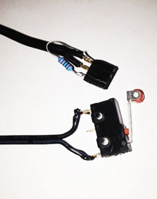
I am building a 3D printer from scratch using the Gen7 1,5 board. Have finished all and am now trying to get the mechanical endstops to work.
Firmware is Teacup.
Endstops are just not working even though i have activated the #define USE_INTERNAL_PULLUPS according to Wiki instruction and added the resistor 10kOhm.
See my config.h here :
/***************************************************************************\
* *
* 3. PINOUTS *
* *
\***************************************************************************/
/*
Machine Pin Definitions
- make sure to avoid duplicate usage of a pin
- comment out pins not in use, as this drops the corresponding code and makes operations faster
*/
#include "arduino.h"
/** \def USE_INTERNAL_PULLUPS
internal pullup resistors
the ATmega has internal pullup resistors on it's input pins which are counterproductive with the commonly used eletronic endstops, so they should be switched off. For other endstops, like mechanical ones, you may want to uncomment this.
*/
#define USE_INTERNAL_PULLUPS
/*
user defined pins
adjust to suit your electronics,
or adjust your electronics to suit this
*/
#define X_STEP_PIN DIO29
#define X_DIR_PIN DIO28
#define X_MIN_PIN DIO0
//#define X_MAX_PIN xxxx
//#define X_ENABLE_PIN xxxx
//#define X_INVERT_DIR
//#define X_INVERT_MIN
//#define X_INVERT_MAX
//#define X_INVERT_ENABLE
#define Y_STEP_PIN DIO27
#define Y_DIR_PIN DIO26
#define Y_MIN_PIN DIO1
//#define Y_MAX_PIN xxxx
//#define Y_ENABLE_PIN xxxx
//#define Y_INVERT_DIR
//#define Y_INVERT_MIN
//#define Y_INVERT_MAX
//#define Y_INVERT_ENABLE
#define Z_STEP_PIN DIO23
#define Z_DIR_PIN DIO22
#define Z_MIN_PIN DIO2
//#define Z_MAX_PIN xxxx
//#define Z_ENABLE_PIN xxxx
//#define Z_INVERT_DIR
//#define Z_INVERT_MIN
//#define Z_INVERT_MAX
//#define Z_INVERT_ENABLE
#define E_STEP_PIN DIO19
#define E_DIR_PIN DIO18
//#define E_ENABLE_PIN
//#define E_INVERT_DIR
//#define E_INVERT_ENABLE
#define PS_ON_PIN DIO15
#define STEPPER_ENABLE_PIN DIO25
#define STEPPER_INVERT_ENABLE
Photo of endstop in attachment.
does anybody have an idea to solve the problem ?
Any help appreciated !
Wangfei
|
Re: Mechanical Endstop in Gen7 1.5 and Teacup October 08, 2013 12:00PM |
Registered: 12 years ago Posts: 2,705 |
You could measure the signal pin and see if it changes from 5v to gnd.
Maybe you should change
//#define X_INVERT_MIN
Pin number seems ok.
Did you try M119 to check if the signals change?
But I'm no teacup user. This is the repetier firmware and host thread. For gen 7 try the generation N+1 Electronics thread. There you see much more users familiar with Gen 7 and Teacup.
Repetier-Software - the home of Repetier-Host (Windows, Linux and Mac OS X) and Repetier-Firmware.
Repetier-Server - the solution to control your printer from everywhere.
Visit us on Facebook and Twitter!
Sorry, only registered users may post in this forum.