Help with 16x2 LCD
Posted by another_reprapper
|
Help with 16x2 LCD April 14, 2012 07:18AM |
Registered: 12 years ago Posts: 51 |
I have set up a 16x2 LCD over I2C via a PCF8574 and set UI_DISPLAY_TYPE==3.
However I think something is causing it to "hang" as the display remains blank and when I try and connect via the host software it hangs during connection.
I set UI_ROWS and UI_COLS.
I also checked my I2C address is 0x4e by tying all the address pins on the PCF8574 to +5V.
I have checked all my pins match those in the firmware. I noted that the firmware specifies 8-bit pins but I am only using 4. I'm assuming this is fine.
I wondered if the line offsets could be the cause:
#define UI_LINE_OFFSETS {0,0x40,0x10,0x50} // 2x16, 2x20, 2x24
I can't seem to find out what these mean to see if they are right for my 4 bit 16x2 display.
I also disabled eeprom and sd support for my sanguinololu board just in case they were bloating the 64k memory.
With UI_DISPLAY_TYPE disabled the firmware works but with it enabled it hangs every time.
Any tips on how to further debug this?
|
Re: Help with 16x2 LCD April 14, 2012 07:58AM |
Registered: 12 years ago Posts: 2,705 |
another_reprapper Wrote:
-------------------------------------------------------
> I have set up a 16x2 LCD over I2C via a PCF8574
> and set UI_DISPLAY_TYPE==3.
>
OK.
> However I think something is causing it to "hang"
> as the display remains blank and when I try and
> connect via the host software it hangs during
> connection.
The I2C communication is blocking if it doesn't get the requested feedback. Possible reasons: Wrong address, communication error caused by to long cable, no pullup resistors for SCL/SDA (don't know if your sanguino has them already on chip, in this schamtic I couldn't find any: http://www.reprap.org/mediawiki/images/8/83/Sanguinololu-schematic.jpg, gen6 has 4,7k to 5V)
Before initialization you should see some black dots. If not you contrast voltage is wrong. You can set it that light, you won't see a thing even if it worked.
>
> I set UI_ROWS and UI_COLS.
> I also checked my I2C address is 0x4e by tying all
> the address pins on the PCF8574 to +5V.
There is a subtype of PCF8574 with different addresses.
> I have checked all my pins match those in the
> firmware. I noted that the firmware specifies
> 8-bit pins but I am only using 4. I'm assuming
> this is fine.
Yes, i2c uses only 4 bit mode. DB0-DB3 should be connected to ground. That way 7 of the 8 pins are used.
>
> I wondered if the line offsets could be the
> cause:
> #define UI_LINE_OFFSETS {0,0x40,0x10,0x50} //
> 2x16, 2x20, 2x24
> I can't seem to find out what these mean to see if
> they are right for my 4 bit 16x2 display.
They are ok. They are the start addresses in LCD ram where the lines have to be stored.
>
> I also disabled eeprom and sd support for my
> sanguinololu board just in case they were bloating
> the 64k memory.
Disabling SD support is enough. Did the same with my Gen6.
>
> With UI_DISPLAY_TYPE disabled the firmware works
> but with it enabled it hangs every time.
>
> Any tips on how to further debug this?
Repetier-Software - the home of Repetier-Host (Windows, Linux and Mac OS X) and Repetier-Firmware.
Repetier-Server - the solution to control your printer from everywhere.
Visit us on Facebook and Twitter!
|
Re: Help with 16x2 LCD April 14, 2012 08:08AM |
Registered: 12 years ago Posts: 31 |
|
Re: Help with 16x2 LCD April 14, 2012 01:44PM |
Registered: 12 years ago Posts: 51 |
Thanks for the tips guys, much appreciated.
I have added 4.7k pullups to SDA and SCL and now it no longer hangs - the host software can connect fine.
I am using a 10k pot to control the contrast and I can see 1 row of black blocks, but nothing else.
DB0-DB3 on my LCD are not connected to ground as they do not even have pins soldered to them, as they are unrequired.
I also checked the chip and I have a PCF8574P, so the address is right.
However the LCD still only shows a row of black dots, nothing more.
Edited 1 time(s). Last edit at 04/14/2012 01:45PM by another_reprapper.
|
Re: Help with 16x2 LCD April 14, 2012 02:06PM |
Registered: 12 years ago Posts: 2,705 |
The black row is a good sign. That is the normal start of a powered LCD before initialization.
With the DB0-3 I'm not sure what happens if they are left floating. At the beginning the LCD is in 8 bit mode and needs a special sequence to get into 4 bit mode. I have connected them and added a connection from one of the ground pins. And my I2C works. But perhaps it is not so important.
For further tests I have added my I2C test software attached. If you have Arduino < 1.0 rename it to i2ctester.pde.
It is a seperate sketch and has nothing to do with your firmware. Compile, Upload and use Serial Monitor with 57600 baud to connect. Address 0x4e is preselected but can be changed with
If you now send a number form 1-255 that bit pattern is assigned to the output pins.
Do the following sequence and test if your pin assignment is correct.( I hope you left the _BV() around the pin numbers.)
1
2
4
8
16
32
64
128
After each change, take your multimeter and check if the pin you think it is has 5V and the other 6 should have 0.
After that you know the PCF is working the way you thought or where you set a wrong pin mask.
Repetier-Software - the home of Repetier-Host (Windows, Linux and Mac OS X) and Repetier-Firmware.
Repetier-Server - the solution to control your printer from everywhere.
Visit us on Facebook and Twitter!
With the DB0-3 I'm not sure what happens if they are left floating. At the beginning the LCD is in 8 bit mode and needs a special sequence to get into 4 bit mode. I have connected them and added a connection from one of the ground pins. And my I2C works. But perhaps it is not so important.
For further tests I have added my I2C test software attached. If you have Arduino < 1.0 rename it to i2ctester.pde.
It is a seperate sketch and has nothing to do with your firmware. Compile, Upload and use Serial Monitor with 57600 baud to connect. Address 0x4e is preselected but can be changed with
#addressAddress in decimal format!
If you now send a number form 1-255 that bit pattern is assigned to the output pins.
Do the following sequence and test if your pin assignment is correct.( I hope you left the _BV() around the pin numbers.)
1
2
4
8
16
32
64
128
After each change, take your multimeter and check if the pin you think it is has 5V and the other 6 should have 0.
After that you know the PCF is working the way you thought or where you set a wrong pin mask.
Repetier-Software - the home of Repetier-Host (Windows, Linux and Mac OS X) and Repetier-Firmware.
Repetier-Server - the solution to control your printer from everywhere.
Visit us on Facebook and Twitter!
|
Re: Help with 16x2 LCD April 14, 2012 07:31PM |
Registered: 12 years ago Posts: 51 |
Thanks ever so much for the help. I couldn't get that I2C test working (for some reason even though I downloaded the library it requires it wouldn't compile).
But no matter: my LCD now works! I think (and this is embarrassing) that the missing pullup resistors were the cause of my problems and as I'd switched to your new version of the firmware released today I didn't update all the configuration correctly in the uiconfig.h file when testing.
To confirm the situation with DB0-3 on the LCD: I have used LCDs on a few occasions in 4 bit mode and have never connected DB0-3 to ground. This may be not be technically correct usage but I can confirm that the LCD works fine if DB0-3 are not tied to ground.
Thank you again for the help, it is much appreciated.
Now I'm onto key configuration which also seems to be working, so far so good.
For future reference for anyone looking to verify I2C data transmission: there is a simple example built into Arduino - "Wire>master_writer" which can be easily modified to enable verification of the HIGH/LOW settings of pins via a multimeter by sending an integer value over I2C. But anyone doing this needs to shift the bits of their I2C address right one binary bit as for some reason this is how the Arduino Wire library addresses I2C. So for example, my I2C device address 0x4e (01001110) became 0x27 (00100111) when using the Arduino Wire library.
Edited 2 time(s). Last edit at 04/14/2012 08:19PM by another_reprapper.
|
Re: Help with 16x2 LCD June 04, 2012 02:41AM |
Registered: 12 years ago Posts: 70 |
|
Re: Help with 16x2 LCD June 07, 2012 10:42AM |
Registered: 12 years ago Posts: 70 |
|
Re: Help with 16x2 LCD June 07, 2012 11:37AM |
Registered: 12 years ago Posts: 2,705 |
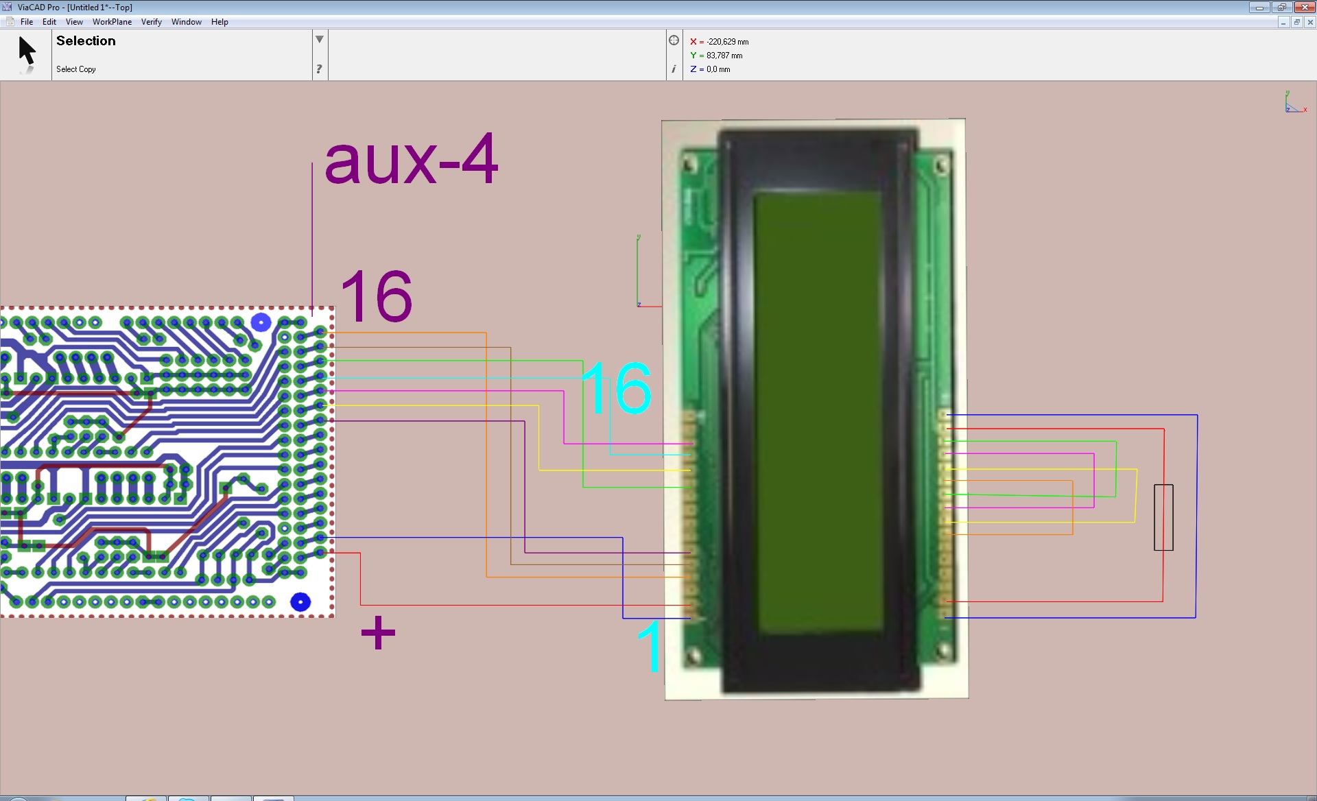
A picture helps if my descriptions are hard to understand. I will add some possible schemes in the manual I'm currently writing.
In your wiring I don't see a connection to V0 (pin 3) for contrast adjustment. I always put a 10K poti and connect the middle pin to v0, so I can change the contrast. The other pins go to vss and vdd (pin 1 and 2). If you have a good contrast without it, you can leave it off course.
Repetier-Software - the home of Repetier-Host (Windows, Linux and Mac OS X) and Repetier-Firmware.
Repetier-Server - the solution to control your printer from everywhere.
Visit us on Facebook and Twitter!
|
Re: Help with 16x2 LCD June 08, 2012 07:44AM |
Registered: 12 years ago Posts: 70 |
|
Re: Help with 16x2 LCD June 11, 2012 04:56PM |
Registered: 13 years ago Posts: 1,797 |
[arduino.cc] may help. also there is something known as a diode trick, place a diode and a 10k resistor in series. this type Hitachi-compatible LCD requires a bias voltage ~0.5-0.8v.
Also remember to GND R/WR pin. many people forget to put lcd into the proper mode by gnd this pin.
crude diagram as i could not find a picture.
vcc 5v
-----
\
/ 10k
\
/
-------------() Vo (pin 3)
|
|
__
-\/- diode
|
-----
---
-
Gnd
Edited 1 time(s). Last edit at 06/11/2012 05:08PM by jamesdanielv.
Also remember to GND R/WR pin. many people forget to put lcd into the proper mode by gnd this pin.
crude diagram as i could not find a picture.
vcc 5v
-----
\
/ 10k
\
/
-------------() Vo (pin 3)
|
|
__
-\/- diode
|
-----
---
-
Gnd

Edited 1 time(s). Last edit at 06/11/2012 05:08PM by jamesdanielv.
Sorry, only registered users may post in this forum.