How to make a hole in object's shell to expose the infill?[solved]
Posted by DeepSOIC
|
How to make a hole in object's shell to expose the infill?[solved] July 24, 2014 12:36PM |
Registered: 9 years ago Posts: 16 |
Hi everyone!
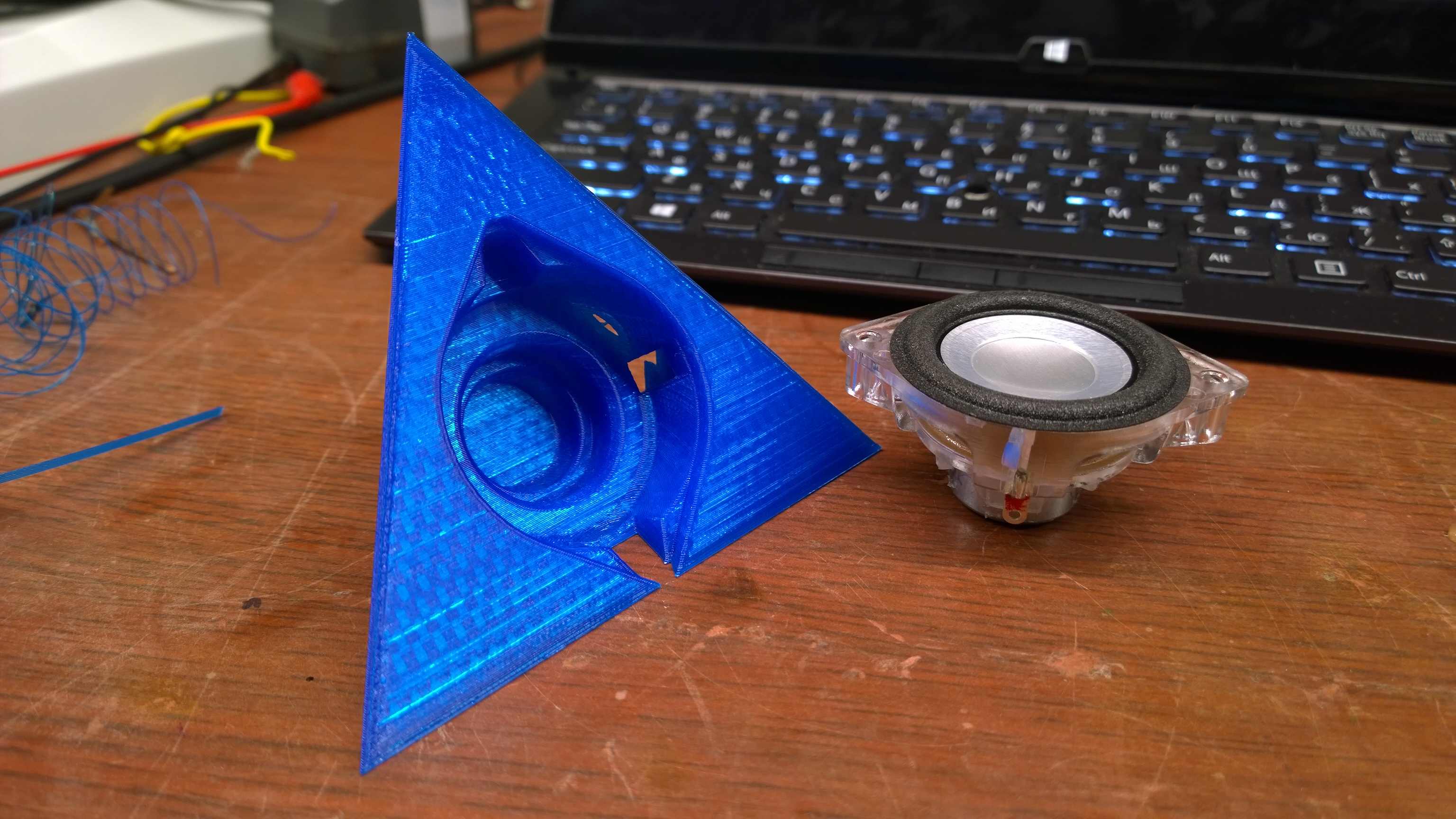
I like making speaker systems, and I realized recently that it's a good idea to have the infill in the whole working volume of a speaker cabinet. The infill will allow to make walls thin (keep them from wobbling) and act as sound absorbing material at the same time, preventing formation of standing waves inside.
However, it turns out that I don't know how to make some part of model's shell go away, i.e. to make a hole/indentation for the driver. I have attached a photo to help understand what I mean.
The first idea was to make the whole cabinet with indentation for the driver as usual, and then dremel out some parts of the shell under the driver. I did it, it works, except that dremeling of PLA turned out to be unexpectedly hard. That took me a lot of time, effort, and the result was very messy (yeah, it all ended up hidden behind the driver, so the mess is not a big concern).
That makes me reconsider an option to force the slicer into doing the job. The only direction that looks promising to me is to trick the slicer into thinking that my printer has two extruders, and tell the slicer that I want to print the shell behind the driver with a second (non-existing) extruder. I'm not sure if it will work, but it is certainly not optimal solution in terms of time since the printer will still try to print the non-existing shell.
If anyone happens to come up with a great idea on how to do this, please share!
Edited 1 time(s). Last edit at 07/25/2014 03:30PM by DeepSOIC.
|
Re: How to make a hole in object's shell to expose the infill? July 24, 2014 03:26PM |
Registered: 10 years ago Posts: 208 |
I don't think the slicer could help you in the way you want.
One solution would be (the sequence is pretty generic and should work with any CAD program)
- model the interior as full solid and make 2 more copies
- use one copy to extrude the walls that you want to be
- intersect above with a second copy - the result will be the shell
- model the structure you want to have in the interior
- use the original of the interior to intersect with the structure
- combine the shell with the interior
|
Re: How to make a hole in object's shell to expose the infill? July 24, 2014 06:20PM |
Registered: 9 years ago Posts: 16 |
Thanks for the answer!
My own idea with fake extruder didn't work - the slicer makes opaque interfaces between materials regardless of a setting that should affect it (a checkbox: print settings/multiple extruders/advanced/interface shells). No progress with Cura and Skeinforge either.
Another idea: separate shell and infill as two simple solids in CAD. Slice them separately: infill object - with 0 perimeters, and shell .. well.. complelely made of perimeters =). And then write a custom script to combine the two resulting g-codes. But I'm not sure it is worth the hassle - dremeling looks easier. And of course - I can write a g-code filter that removes some pieces of perimeters, but that involves some 3d geometry, thus it's waay too much work.
And one more idea. I'm thinking if it's possible to utilize support material generator. Like - make thin walled shell STL, and tell the slicer to support everything...
eem.. As I got it, you are basically telling me that I should not use slicer's infilling at all and model the whole internal structure in CAD program. Yeah, might work, but it's a bit too complex, produce a hugely complex geometry and maybe it even can confuse the slicer.Quote
3Dmaker4U
- model the interior as full solid and make 2 more copies
- use one copy to extrude the walls that you want to be
- intersect above with a second copy - the result will be the shell
- model the structure you want to have in the interior
- use the original of the interior to intersect with the structure
- combine the shell with the interior
My own idea with fake extruder didn't work - the slicer makes opaque interfaces between materials regardless of a setting that should affect it (a checkbox: print settings/multiple extruders/advanced/interface shells). No progress with Cura and Skeinforge either.
Another idea: separate shell and infill as two simple solids in CAD. Slice them separately: infill object - with 0 perimeters, and shell .. well.. complelely made of perimeters =). And then write a custom script to combine the two resulting g-codes. But I'm not sure it is worth the hassle - dremeling looks easier. And of course - I can write a g-code filter that removes some pieces of perimeters, but that involves some 3d geometry, thus it's waay too much work.
And one more idea. I'm thinking if it's possible to utilize support material generator. Like - make thin walled shell STL, and tell the slicer to support everything...
|
Re: How to make a hole in object's shell to expose the infill? July 24, 2014 08:32PM |
Registered: 13 years ago Posts: 2,947 |
You could try Cura and in the expert options there is an option to keep open faces.
| FFF Settings Calculator | Gcode post processors | Geometric Object Deposition Tool Blog |
| Tantillus.org | Mini Printable Lathe | How NOT to install a Pololu driver |
|
Re: How to make a hole in object's shell to expose the infill? July 25, 2014 05:56AM |
Registered: 9 years ago Posts: 16 |
Thanks for the answer! I have searched for help on this option and found that:Quote
Sublime
You could try Cura and in the expert options there is an option to keep open faces.
Doesn't look promising.Quote
Daid
"Keep open faces" happens in a step before that [CSG union of everything]. What Cura does at first, is taking a knife and slicing your model into tiny slices. Each slice is a layer as you might understand. But, 3D models are never perfect, so what I end up with is a lot of small line segments in a 2D plane. The next thing I do is joining up small gaps between the line segments, and any line segment that makes a full circle is stored for later reference. Any line segment that fails to make a full circle is normally discarded. UNLESS you have this option checked, then it makes a line from one end to the other to close up the line.
Simple example would be to take a cube, remove 1 side from the cube, save it, load it in Cura. It won't generate any GCode because no slice is closed, unless you check the "keep open faces" then it will effectively fake in the removed surface again.
Results may vary, and it usually works best in combination with "Type-B combine everything".
What I have just found is that it is possible to make adjustments to every solid in a print separately in Slic3r's plater. That should nail my problem. All I have to do now is split the cabinet into a shell and an interior, combine them in plater and configure the interior to have no perimeters/no solid layers. That must be it, I'll try that soon.
|
Re: How to make a hole in object's shell to expose the infill? July 25, 2014 03:19PM |
Registered: 9 years ago Posts: 16 |
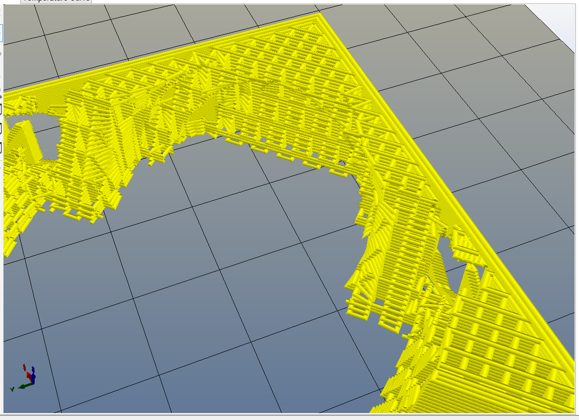
So, the problem is solved. I had to make two models: one for the solid airproof shell, the other for the sparse infill (still a simple solid, just indicating where to make the infill). I joined them in Slic3r's plater, made an AMF file, re-imported it into the plater, modified the settings for interior part so that it is printed with normal extruder and it has no perimeters and solid infill. And voila! (see the attached picture, where a few layers in the middle of the model are shown). Long live Slic3r!!!
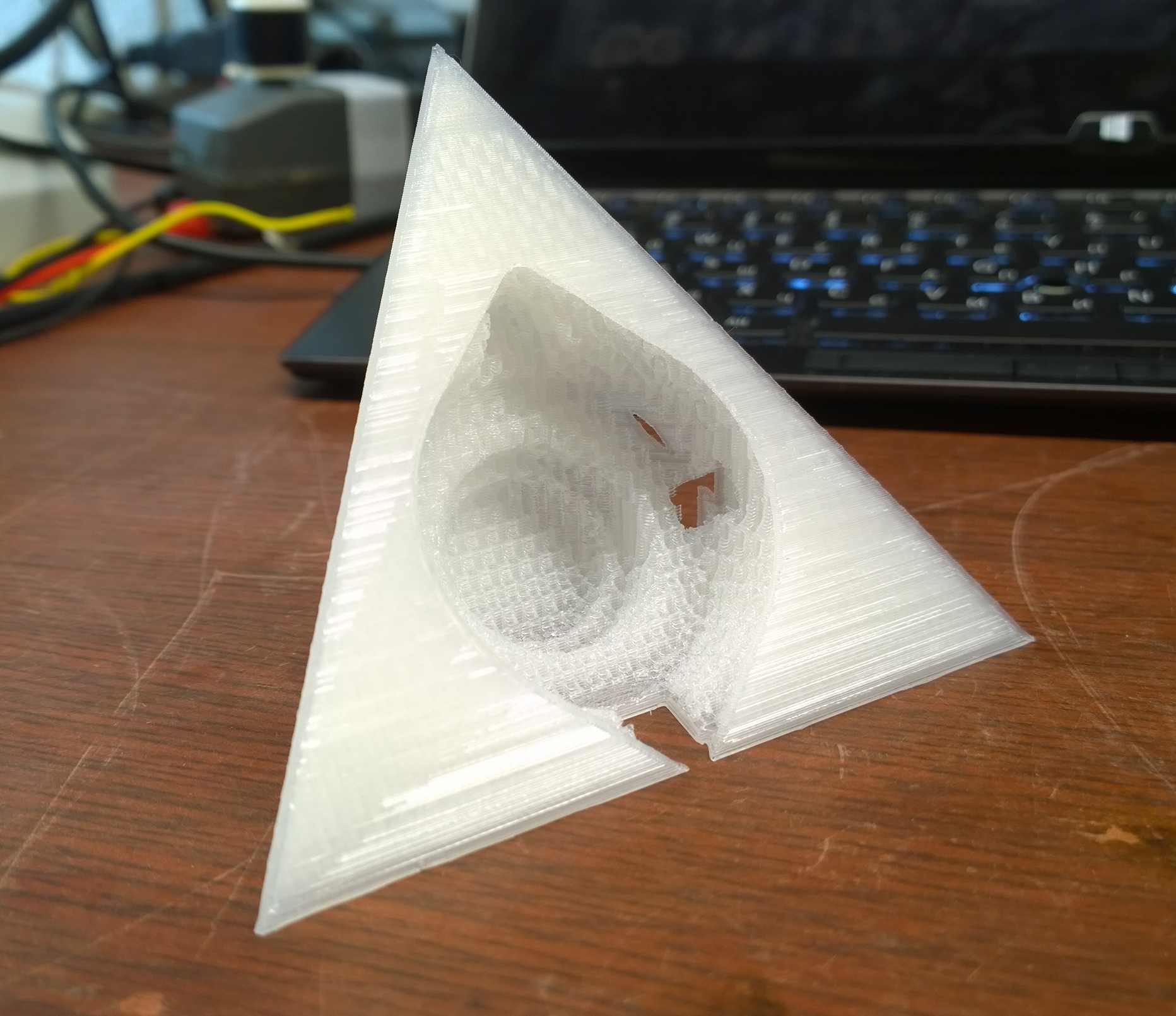
EDIT: When I started to print, it turned out to print not good: there is a small gap between the shell and the infill, so they do not adhere to each other. Now I'm figuring out an easy way to combat this.
EDIT2: attached a photo of a successful print.
Edited 2 time(s). Last edit at 07/25/2014 06:58PM by DeepSOIC.
Sorry, only registered users may post in this forum.