Mating Issues Between Two Printed Parts
Posted by GaM3r2Xtreme
|
Mating Issues Between Two Printed Parts April 07, 2016 04:47PM |
Registered: 8 years ago Posts: 3 |
Hey Everyone,
I've been 3D printing for about a year now and have ran into plenty of common problems over that span of time, but I have never been able to understand a good method of having two printed parts mate without any interference or huge gaps between the two. Just as a simple example, think of a solid rod sliding through a thick pipe. The measurements are arbitrary when used in the text and the attached images, and most of my slicing background comes from using Cura. The printer I have is a HICTOP Prusa i3 as well, for anyone curious to know.
First off, we have this thick pipe where each of the slices, 0.1 to 0.3mm in thickness, would look like washers. If a 0.4mm extruder were to be used with a 0.4mm shell thickness setting, one would think the path traveled by the head of the printer would offset from the inner hole by +0.2mm and the outer edge by -0.2mm. This would keep all the dimensions desired at the correct length they are suppose to be. Let's say the inner diameter is expected to be 5mm while the outer diameter is 10mm. This would mean that the printer head would follow a circular path with a diameter or 5.4mm and 9.6mm. See "Pipe_1" for a visual representation.
The solid rod is desired to have a diameter of 5mm, which would mean that the printer needs to follow a circular path of 4.6mm in order to print this part correctly. See "Rod_1" for a visual representation.
Great, so we design these two parts with the desired dimensions in a preferred CAD software exactly as we would like and theoretically the parts should print correctly and mate as intended. Now I know there are tolerances, and the printer will not follow the exact path diameters described above, so importing the designed STL files with exact dimensions will not work. Instead, let's say we give the rod some wiggle room and cut the diameter down to 4.8mm to give a 0.1mm gap between the two parts. The parts are printed, and there are still clearance issues and the rod will not slide in a smooth manner down the pipe, if at all.
Why is this the case? Is it possible that the slicer program is actually making the print head follow the actual edges of the model, leaving a 0.2mm trail of extra plastic on the inside and outside of the parts, as seen in "Pipe_2" and "Rod_2" images? Should a gap of at least 0.4mm be designed in between the two parts within the CAD file in order to compensate?
|
Re: Mating Issues Between Two Printed Parts April 07, 2016 05:18PM |
Registered: 9 years ago Posts: 978 |
Maybe you're not aware... 3D printers approximate circles with a series of straight line segments. So the inner surface of your pipe will be a polygon.The vertices of the polygon will be slightly outside the circle, and the middle of each side will be slightly inside. (I'd expected to find a setting in Slic3r or Cura to control this, but couldn't find one in either). So holes will always by slightly smaller than their expected diameter, and rods will always be slightly larger.
When I need a hole to be circular, I run a drill through it after printing. When I need two parts to fit accurately, there's usually a bit of sanding involved.
When I need a hole to be circular, I run a drill through it after printing. When I need two parts to fit accurately, there's usually a bit of sanding involved.
|
Re: Mating Issues Between Two Printed Parts April 07, 2016 05:19PM |
Registered: 10 years ago Posts: 651 |
Slic3r's doing the math for extrusion width and following that. Slic3r knows that plastic exits the nozzle and actually swells to larger than the size of the nozzle, Eg. Die Swell and that the layer is squeezed onto the layer before it, thus the extrusion width. A .4 nozzle doesn't create a .4 width line, it'll probably be something like .67. If you design a part at .4 wall thickness, you'll still get a .67 thick wall. If you open a Slic3r generated gcode file in a text editor. you'll see what it calculated the extrusion width to be.
This is just calculation, it may not be what your printer is actually doing. You can calibrate your extrusion multiplier setting in Slic3r to make the extrusion width setting and actual extrusion width to be very close. Take a look at this guide.
Of course the plastic shrinks a little too, so you have to compensate for that. When I calibrate my machines, I usually calibrate just the X and Y carriage movements. I tell it to move 100mm and then measure from a static part somewhere to make sure it moved 100mm, if not I adjust my steps per mm in EEPROM until I've got it right and write that to my firmware. Then I know the nozzle always moves 100mm when I tell it, and everything else is just properties of the plastic.
So all I have to do is print a couple of calibration parts when I get a different spool of plastic cause they're all different. I do an extusion width calibration to get that right and I also print a cube. I measure the cube, I then adjust steps per mm for and write to eeprom, reprint the test, and measure. Repeat until I've got accurate size. Then I write those settings (extrusion multiplier too) on the spool for when I swap out to another spool and come back to it, I know which settings to use.
Edit: And like mentioned, circles are just many segments, they're always undersized when they actually print. Looks like you've designed with that in mind already, giving .4mm of room I would think to be enough.
Also unless you have perfect vertical alignment of the layers, there are going to be ripples that will catch one another, they won't be perfectly smooth.. Using the cylinder in a pipe example, if the cylinder was bent even slightly, it wouldn't slide in the pipe unless your tolerances accounted for that too..
Edited 5 time(s). Last edit at 04/07/2016 05:35PM by FA-MAS.
|
Re: Mating Issues Between Two Printed Parts April 07, 2016 06:48PM |
Registered: 8 years ago Posts: 778 |
I did some of these alignment tests with my printer some time ago.
With a 0.3mm nozzle and PLA I can tweak the extrusion so that parts fit snug together when using a gap of 0.3mm.
However, this means the dimensions are not really as planned.
One way around this is do some tests first for rods (pins) and holes.
Check the dimensional accuracy with your best settings and adjust your design accordingly.
Would mean for example you design a 4mm hole to be 4.15mm and a 4mm pin to be 3.85mm for example.
Since you always need some time for manual cleaning and smoothing it often pays off to print holes slightly smaller and to drill them to the right size.
Same for other case of a rod, sand it smooth.
As said above a slicer usually calculates a circle either as a combination of straight lines or as a combination of arcs - depends on the slicer and diameter.
So when designing holes do some tests in different diameters and with different amounts of line sections to measure the difference in roundness and diameter.
|
Re: Mating Issues Between Two Printed Parts April 08, 2016 07:33AM |
Registered: 8 years ago Posts: 413 |
You can research how the slicers calculate the material requirement.
The slicer auto calculation considers the layer height not just the nozzle size. So it has a different value dependant on the layer height. If you try to use fixed width values or the multiplier you will probably find these are only valid for the layer height you used. Theres another rule of thumb that says don't used fixed widths greater than 1.2 x the nozzle diameter.
Oh and you can change the outer perimeter first/last option. Last and slow is common but if last it will flow around the inner perimeter so be "oversize". If you print it first you will be more accurate but have more difficulties with overhangs.
|
Re: Mating Issues Between Two Printed Parts April 08, 2016 08:46AM |
Registered: 11 years ago Posts: 5,780 |
See Slic3r flow math
When you convert your CAD file to STL, the curves become polygons because the surface is broken into triangles. That changes the dimensions of both holes and solids. That is at least part of the problem. Any misregistration on the layers creates a rough surface that will make sliding close fitting parts together difficult. Any calibration error in the X and Y axes will cause solids and holes to be misshapen, and they won't fit together properly, especially if a round post has to rotate inside a hole. Any nonorthogonality of the X, Y, and Z axes will result in misshapen objects that won't fit together properly.
When you try to print parts to close tolerances the printer has to be extremely well calibrated, and even well made so it doesn't flex or wobble while printing. The sloppier the printer, the looser the tolerances will have to be to print parts that fit together.
Edited 1 time(s). Last edit at 04/08/2016 08:47AM by the_digital_dentist.
Ultra MegaMax Dominator 3D printer: [drmrehorst.blogspot.com]
|
Re: Mating Issues Between Two Printed Parts April 08, 2016 04:45PM |
Registered: 8 years ago Posts: 3 |
Thanks for all the help and quick replies everyone!
I did know circles are estimated via polygon representation, but I didn't take that into consideration. This and the die swell makes sense as to why the a hole could end up smaller than what was intended. I found this thread on the ultimaker website talking about the Cura software and how it calculates the placement of the extruded plastic.
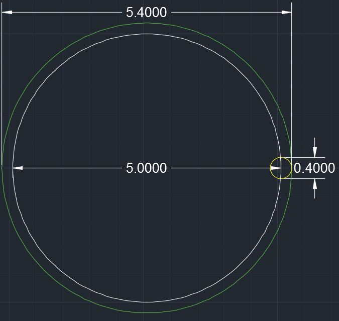
Apparently the CAD program will also estimate a circle as a polygon inscribed within. After generating a .stl file, Cura would see this polygon as separate linear walls to offset from. I'm sure Slic3r would offset in the same direction as well, but how much would depend on it's own method of calculation. I have attached another image of what I would assume to be happening throughout the whole process. The white circle would represent the desired circle, The green polygon would acts as a simple estimation to the circle (over simplified in order to show detail a little better). And the orange would be the path the print head would follow, and the yellow circle would be the extruded plastic.
As far as I can tell, taking a drill bit would be the best way to clean out the extra plastic within the printed hole. If a hole would typically become smaller than intended, what would a pin turn out to be? Would it be a little smaller as well because the same type of line segment estimation would inscribe on the inside of the intended diameter?
I did know circles are estimated via polygon representation, but I didn't take that into consideration. This and the die swell makes sense as to why the a hole could end up smaller than what was intended. I found this thread on the ultimaker website talking about the Cura software and how it calculates the placement of the extruded plastic.
Apparently the CAD program will also estimate a circle as a polygon inscribed within. After generating a .stl file, Cura would see this polygon as separate linear walls to offset from. I'm sure Slic3r would offset in the same direction as well, but how much would depend on it's own method of calculation. I have attached another image of what I would assume to be happening throughout the whole process. The white circle would represent the desired circle, The green polygon would acts as a simple estimation to the circle (over simplified in order to show detail a little better). And the orange would be the path the print head would follow, and the yellow circle would be the extruded plastic.
As far as I can tell, taking a drill bit would be the best way to clean out the extra plastic within the printed hole. If a hole would typically become smaller than intended, what would a pin turn out to be? Would it be a little smaller as well because the same type of line segment estimation would inscribe on the inside of the intended diameter?
Sorry, only registered users may post in this forum.