Inductive sensor aways OPEN
Posted by gustavogoulart
|
Inductive sensor aways OPEN April 14, 2015 05:33AM |
Registered: 9 years ago Posts: 51 |
Hi there everyone!
I bought one inductive sensor for my Prusa. I got the cables with the resistors on, they are connected BLUE and BLACK to the ZEndstop on the RAMPS 1.4 and the BROWN, direct to the 12V line of the PSU (I will hookit to the ramps too, but for testing it was easier).
The situation:
It lights up the LED when near metal, the aluminum bed also works perfectly lighting up the LED, but...when I gcode M199, it aways return OPEN for the Z. If I invert the logics, It will aways return Triggered and will stop the Z to move down.
Well, thats it...
Thank you so much.
|
Re: Inductive sensor aways OPEN April 14, 2015 08:43AM |
Registered: 10 years ago Posts: 869 |
|
Re: Inductive sensor aways OPEN April 14, 2015 09:26AM |
Registered: 9 years ago Posts: 51 |
|
Re: Inductive sensor aways OPEN April 14, 2015 11:24AM |
Registered: 10 years ago Posts: 1,401 |
|
Re: Inductive sensor aways OPEN April 14, 2015 11:27AM |
Registered: 9 years ago Posts: 51 |
|
Re: Inductive sensor aways OPEN April 14, 2015 11:36AM |
Registered: 10 years ago Posts: 1,401 |
|
Re: Inductive sensor aways OPEN April 14, 2015 11:40AM |
Registered: 9 years ago Posts: 51 |
Ok, I will try it now.
I´m followeing two topics on this problem right now, one I believe you helped the guy with a similar problem one year ago. And hes helping me now! (the beaty of opensource! ) ... I´m connecting the wires like he told me now.
Black on the Signal Z estop on Ramps
Brown on the 12V + IN also on ramps
Blue on the 12V - IN ramps...
I´m followeing two topics on this problem right now, one I believe you helped the guy with a similar problem one year ago. And hes helping me now! (the beaty of opensource!
) ... I´m connecting the wires like he told me now.Black on the Signal Z estop on Ramps
Brown on the 12V + IN also on ramps
Blue on the 12V - IN ramps...
|
Re: Inductive sensor aways OPEN April 14, 2015 12:08PM |
Registered: 9 years ago Posts: 51 |
|
Re: Inductive sensor aways OPEN April 14, 2015 12:17PM |
Registered: 9 years ago Posts: 51 |
|
Re: Inductive sensor aways OPEN April 14, 2015 12:28PM |
Registered: 10 years ago Posts: 1,401 |
That's why I don't use resistors, they are less than accurate, I use a 5 volts regulator (LM7805) to secure a 5 volts signal. If you didn't fry the board you are still ok.
For testing, untill you get it working will be best to use the 5 volts from ramps endstop pins.
Brown to pin 3 or +, blue to pin 2 or - and black to pin 1 or signal. Remove the pullup resistor for Z min in the firmware and test. If doesn't work that way, you might have to change it to an NPN sensor.
|
Re: Inductive sensor aways OPEN April 14, 2015 12:32PM |
Registered: 10 years ago Posts: 869 |
Did you ever have the sensor output connected directly to the endstop sense pin without a voltage divider? A 12V fed PNP sensor will output nearly 12V and would fried that pin as it's only ~5V safe. Your 100k and 150k resistors create a voltage divider dropping the voltage to ~4.8 volts, if you have them located in the correct spot. Post a picture of your divider.
Since you have a RAMPS board, if you did fry one of the endstops, you have 2 more you can use. Switch the Z axis with one of the (most likely) unused X or Y endstops. Just swap the pin numbers in the pins.h file if indeed the pin is bad (you can test by shorting S to ground and checking the endstop status using M119.
Since you have a RAMPS board, if you did fry one of the endstops, you have 2 more you can use. Switch the Z axis with one of the (most likely) unused X or Y endstops. Just swap the pin numbers in the pins.h file if indeed the pin is bad (you can test by shorting S to ground and checking the endstop status using M119.
|
Re: Inductive sensor aways OPEN April 14, 2015 12:40PM |
Registered: 10 years ago Posts: 1,401 |
|
Re: Inductive sensor aways OPEN April 14, 2015 12:41PM |
Registered: 9 years ago Posts: 51 |
Quote
ggherbaz
That's why I don't use resistors, they are less than accurate, I use a 5 volts regulator (LM7805) to secure a 5 volts signal. If you didn't fry the board you are still ok.
For testing, untill you get it working will be best to use the 5 volts from ramps endstop pins.
Brown to pin 3 or +, blue to pin 2 or - and black to pin 1 or signal. Remove the pullup resistor for Z min in the firmware and test. If doesn't work that way, you might have to change it to an NPN sensor.
By that you mean, put a 3 pin plug and plug it to the z endstop connectinos on ramps entirely? Like if ti was a normal Endstop?
|
Re: Inductive sensor aways OPEN April 14, 2015 12:43PM |
Registered: 9 years ago Posts: 51 |
Quote
cdru
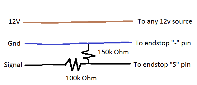
Did you ever have the sensor output connected directly to the endstop sense pin without a voltage divider? A 12V fed PNP sensor will output nearly 12V and would fried that pin as it's only ~5V safe. Your 100k and 150k resistors create a voltage divider dropping the voltage to ~4.8 volts, if you have them located in the correct spot. Post a picture of your divider.
Since you have a RAMPS board, if you did fry one of the endstops, you have 2 more you can use. Switch the Z axis with one of the (most likely) unused X or Y endstops. Just swap the pin numbers in the pins.h file if indeed the pin is bad (you can test by shorting S to ground and checking the endstop status using M119.
No, I´ve never connected it without the resistors. And I just tryed the printer with the endstop, everything is working fine.
|
Re: Inductive sensor aways OPEN April 14, 2015 12:57PM |
Registered: 9 years ago Posts: 51 |

|
Re: Inductive sensor aways OPEN April 14, 2015 01:08PM |
Registered: 9 years ago Posts: 51 |
|
Re: Inductive sensor aways OPEN April 14, 2015 02:00PM |
Registered: 10 years ago Posts: 869 |
Your wiring is wrong. The 100k ohm resistor should be between the two wires and the 150k ohm resistor should between the sensor output (black wire) and where the 100k ohm resistor attaches. See the wonderful drawing skills in the image below.
|
Re: Inductive sensor aways OPEN April 14, 2015 02:05PM |
Registered: 9 years ago Posts: 51 |

|
Re: Inductive sensor aways OPEN April 14, 2015 02:07PM |
Registered: 9 years ago Posts: 51 |
|
Re: Inductive sensor aways OPEN April 14, 2015 02:20PM |
Registered: 10 years ago Posts: 869 |
|
Re: Inductive sensor aways OPEN April 14, 2015 02:22PM |
Registered: 9 years ago Posts: 51 |
|
Re: Inductive sensor aways OPEN April 14, 2015 02:26PM |
Registered: 10 years ago Posts: 869 |
Way higher for what? Anything over about 3V is considered high by the microcontroller. Even if the supply voltage monetarily dropped down a few volts it still would be high enough to be considered high. Sure with a higher precision resistor you could get a bit closer. But it's not that necessary when close enough will do.Quote
ggherbaz
That is true as long as he used gold banded resistors, if silver, that 4.8 could be way higher.
Why do you think that it can't work with a PNP sensor? The 150k Ohm resistor very weakly pulls down the pin to low. When the sensor is triggered, it causes the pin to go high. Low. High. That's what an input pin is designed to detect. Now depending on if the sensor is NC or NO will change whether the logic should be inverted. You'd want to disable the pullup resistor though for a PNP sensor.Quote
The main problem is that I don't think the mega can work with PNP sensors, if it does something needs to be change it in the firmware.
Edited 1 time(s). Last edit at 04/14/2015 02:27PM by cdru.
|
Re: Inductive sensor aways OPEN April 14, 2015 03:08PM |
Registered: 9 years ago Posts: 51 |
|
Re: Inductive sensor aways OPEN April 15, 2015 07:38AM |
Registered: 9 years ago Posts: 51 |
Hi guys, I thought I could leave you alone 
All hardware stuff is working properly...but...
I followed every single tutorial I could found about the marlin configuration, and the problem I cant solve now is the Z offset. I send the Gcode through Pronterface, but everytime I do homming it goes a litle bit higher than I setted with the paper sheet.
thanks
|
Re: Inductive sensor aways OPEN April 15, 2015 09:55AM |
Registered: 10 years ago Posts: 869 |
|
Re: Inductive sensor aways OPEN April 15, 2015 10:04AM |
Registered: 9 years ago Posts: 51 |
I maybe wrong, but I feel like my arduino IDE is not uploading my marlin.ino, although it says so.
And I´m a bit confuse about wich method to use, if I send gcods through Pronterface and make it record it with m500 or if I just go on the marlin.ino and type the value. One way or another it seems not to work as espected.
Questions
1 - The sensor must be about 1 mm from the bed, when nozzle is scratching the paper sheet?
2 - Does it make any difference the distance when the sensor triggers? I mean, I can set its fisical height by hand from 1 to almost 4 mm and it will still light up the LED
3 - There is a line on Marlin to prevent Gcode to be recorded on the EEPROM, right? If I change that is there any colateral effect on how the Arduino IDE will update the marlin on the board?
Thanks
|
Re: Inductive sensor aways OPEN April 15, 2015 10:47AM |
Registered: 10 years ago Posts: 1,401 |
1. No, your sensor will be at the offset distance.
2. The only difference it makes is the offset distance that the axis will have to move down to set the nozzle at 0.1 from built plate. It is always better to locate the sensor as close to the nozzle as possible.
3. Uncomment EEPROM in Marlin, you will be able to modify the firmware only through Arduino ide. Any modification done from lcd or G code won't be save.
|
Re: Inductive sensor aways OPEN April 15, 2015 10:50AM |
Registered: 9 years ago Posts: 51 |
It just doesn´t care about what distance I put on Marlin at z probe offset. It aways raises the Z axis and maintain what looks like to bem the same distance between the sensor and the bed.
That behavior is making me think that de arduino IDE is not recording the new versions I put to apload. And I don´t know any way to ensure that.
What Gcode can I use to see whats inside my board?
That behavior is making me think that de arduino IDE is not recording the new versions I put to apload. And I don´t know any way to ensure that.
What Gcode can I use to see whats inside my board?
|
Re: Inductive sensor aways OPEN April 15, 2015 10:53AM |
Registered: 9 years ago Posts: 51 |
|
Re: Inductive sensor aways OPEN April 15, 2015 11:31AM |
Registered: 10 years ago Posts: 1,401 |
Did you uncommented the EEPROM setting and allow chitchat in configuration h file? If so after any modification with g code will be saved with M500. Also, you might have to allow your Z axis to pass min position in configuration h too.
#define min_software_endstops true // If true, axis won't move to coordinates less than HOME_POS.
Change true to false
Edited 1 time(s). Last edit at 04/15/2015 11:32AM by ggherbaz.
#define min_software_endstops true // If true, axis won't move to coordinates less than HOME_POS.
Change true to false
Edited 1 time(s). Last edit at 04/15/2015 11:32AM by ggherbaz.

Sorry, only registered users may post in this forum.