Gen7 + Repetier Extention Board
geschrieben von Night-Fly
|
Gen7 + Repetier Extention Board 11. October 2013 10:51 |
Registrierungsdatum: 12 Jahre zuvor Beiträge: 22 |
Moin,
Ich bin gerade dabei meinen Prusa gegen einen Mendel90 zu tauschen .. bzw ihm dazuzustellen damit er nicht so alleine ist ....
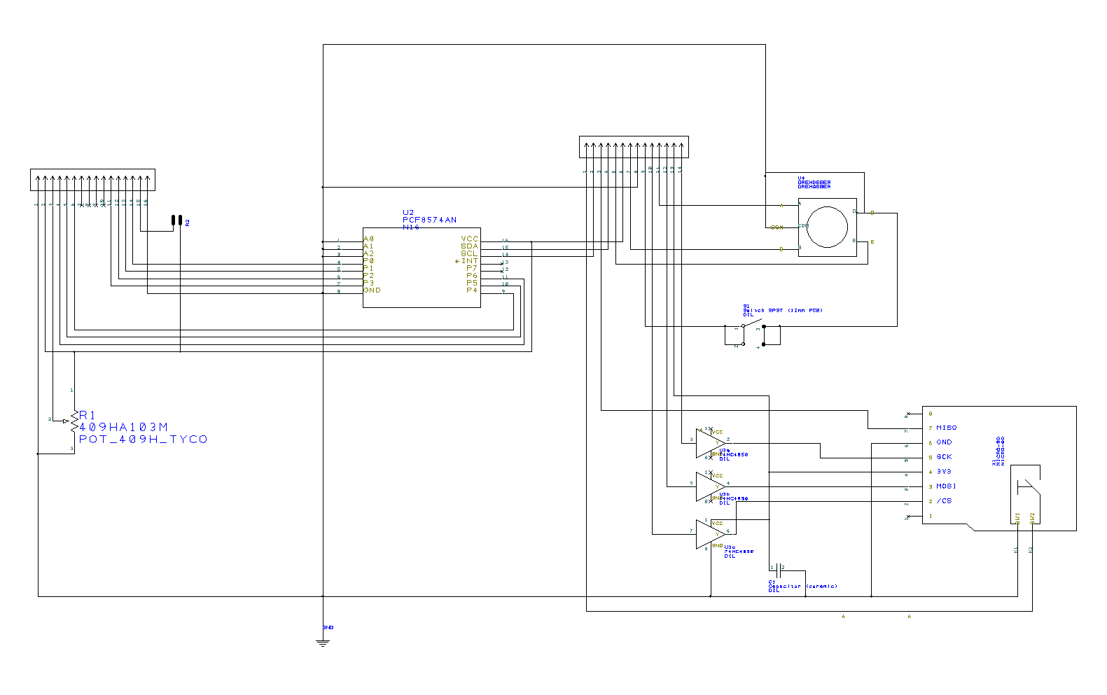
Ich nutze die Gen7 1.4 Und habe mir ein Extention Board konsturiert. Das Board hat eine Lüftersteuerung drauf, sd Card Sockel, Bluetoothmodul, Resettaster, Dehencoder und LCD Display. Nein der Quatum Flux Kompensatur und Warp Antrieb sind noch nicht implementiert ...
Lüfter , Bluetooth, Resettaster und Drehencoder sind direkt am Atmega dran, das LCD jage ich über einen PCF8574A.
Ich hab in der Repetier Firmware sd und LCD aktiviert und erfreue mich seid über einer Stunde über "Binäre Sketchgröße: 90.326 Bytes (von einem Maximum von 63.488 Bytes)" Nehm ich testweise SD Card raus hänge ich bei 73kb Ich hab dem Controller auch schon versucht klar zu machen das er sich wegen son paar kb nicht so anstellen soll aber der will nicht. Ich befürchte der ATMega644p wird dann in einer meiner Microcontrollerbasteleien asyl bekommen und gegen einen 1284P ausgetauscht werden müssen oder sehe ich das falsch ? Womit die eigendlich Frage warum das nicht geht hinfällig sein dürfte aber ganz viele Augen sehen ja bekanntlich mehr als 2 von daher wärs nett wenn wer nen Fehler findet mir das zu verraten
Ich sitz jetzt hier seid 3 Stunden mit meinem Drucker und Steckbrett und versuche das zum laufen zu bekommen ehe ich Platinen ätze. Dummerweise komm ich grad nicht weiter zumal dieser Apothekenladen in Kiel den 1284P nichtmal im Sortiment hat. (Selbst wenn wäre das egal da der in Kiel sowieso nix vorrätig hat). Somit bleibt die Frage hab ich da irgendwo nen Denkfehler in meiner Konstruktion .. so allgemein und so ..
Schaltpläne sind in Eagle bzw. Designspark gezeichnet ... war zu faul das Eagle teil nochmal zu machen
Pins die ich mir so ausgesucht habe ...
SDCarddetect PD2 D10
OK PD3 D11
A PC5 D21
B PC4 D20
SDSS PA7 D24
Fan PD5 D13
Configuration.h Repetier
#ifndef SDSUPPORT // Some boards have sd support on board. These define the values already in pins.h
#define SDSUPPORT true
/** If set to false all files with longer names then 8.3 or having a tilde in the name will be hidden */
#define SD_ALLOW_LONG_NAMES false
// Uncomment to enable or changed card detection pin. With card detection the card is mounted on insertion.
#define SDCARDDETECT 10
#define FEATURE_FAN_CONTROL true
/** For displays and keys there are too many permutations to handle them all in once.
For the most common available combinations you can set the controller type here, so
you don't need to configure uicong.h at all. Controller settings > 1 disable usage
of uiconfig.h
0 = no display
1 = Manual definition of display and keys parameter in uiconfig.h
The following settings override uiconfig.h!
2 = Smartcontroller from reprapdiscount on a RAMPS or RUMBA board
3 = Adafruit RGB controller
4 = Foltyn 3DMaster with display attached
5 = ViKi LCD - Check pin configuration in ui.h for feature controller 5!!! sd card disabled by default!
*/
#define FEATURE_CONTROLLER 1
/**
Select the language to use.
0 = english
1 = german
2 = dutch
3 = brazilian portuguese
4 = italian
*/
#define UI_LANGUAGE 1
// This is line 2 of the status display at startup. Change to your like.
#define UI_VERSION_STRING2 "Möp Möp Möp"
/** How many ms should a single page be shown, until it is switched to the next one.*/
#define UI_PAGES_DURATION 4000
/** Uncomment if you don't want automatic page switching. You can still switch the
info pages with next/previous button/click-encoder */
#define UI_DISABLE_AUTO_PAGESWITCH true
/** Time to return to info menu if x millisconds no key was pressed. Set to 0 to disable it. */
#define UI_AUTORETURN_TO_MENU_AFTER 30000
#define FEATURE_UI_KEYS 0
/* Normally cou want a next/previous actions with every click of your encoder.
Unfotunately, the encoder have a different count of phase changes between clicks.
Select an encoder speed from 0 = fastest to 2 = slowest that results in one menu move per click.
*/
#define UI_ENCODER_SPEED 1
/** \brief bounce time of keys in milliseconds */
#define UI_KEY_BOUNCETIME 10
/** \brief First time in ms until repeat of action. */
#define UI_KEY_FIRST_REPEAT 500
/** \brief Reduction of repeat time until next execution. */
#define UI_KEY_REDUCE_REPEAT 50
/** \brief Lowest repeat time. */
#define UI_KEY_MIN_REPEAT 50
#define FEATURE_BEEPER false
uiconfig.h
#define UI_DISPLAY_TYPE 3
/** Number of columns per row
Typical values are 16 and 20
*/
#define UI_COLS 20
/**
Rows of your display. 2 or 4
*/
#define UI_ROWS 4
/* What type of chip is used for I2C communication
0 : PCF8574 or PCF8574A or compatible chips.
1 : MCP23017
*/
#define UI_DISPLAY_I2C_CHIPTYPE 0
// 0x40 till 0x4e for PCF8574, 0x40 for the adafruid RGB shield, 0x40 - 0x4e for MCP23017
// Official addresses have a value half as high!
#define UI_DISPLAY_I2C_ADDRESS 0x40
// For MCP 23017 define which pins should be output
#define UI_DISPLAY_I2C_OUTPUT_PINS 65504
// Set the output mask that is or'd over the output data. This is needed to activate
// a backlight switched over the I2C.
// The adafruit RGB shields enables a light if the bit is not set. Bits 6-8 are used for backlight.
#define UI_DISPLAY_I2C_OUTPUT_START_MASK 0
// For MCP which inputs are with pullup. 31 = pins 0-4 for adafruid rgb shield buttons
#define UI_DISPLAY_I2C_PULLUP 31
/* How fast should the I2C clock go. The PCF8574 work only with the lowest setting 100000.
A MCP23017 can run also with 400000 Hz */
#define UI_I2C_CLOCKSPEED 100000L
/**
Define the pin
*/
#if UI_DISPLAY_TYPE==3 // I2C Pin configuration
#define UI_DISPLAY_RS_PIN _BV(6)
#define UI_DISPLAY_RW_PIN _BV(5)
#define UI_DISPLAY_ENABLE_PIN _BV(4)
//#define UI_DISPLAY_D0_PIN _BV(0)
//#define UI_DISPLAY_D1_PIN _BV(1)
//#define UI_DISPLAY_D2_PIN _BV(2)
//#define UI_DISPLAY_D3_PIN _BV(3)
#define UI_DISPLAY_D4_PIN _BV(3)
#define UI_DISPLAY_D5_PIN _BV(2)
#define UI_DISPLAY_D6_PIN _BV(1)
#define UI_DISPLAY_D7_PIN _BV(0)
void ui_init_keys() {
#if UI_HAS_KEYS!=0
UI_KEYS_INIT_CLICKENCODER_LOW(20,21); // click encoder on pins 47 and 45. Phase is connected with gnd for signals.
UI_KEYS_INIT_BUTTON_LOW(11); // push button, connects gnd to pin
// UI_KEYS_INIT_BUTTON_LOW(5);
// UI_KEYS_INIT_BUTTON_LOW(6);
// UI_KEYS_INIT_BUTTON_LOW(11);
// UI_KEYS_INIT_BUTTON_LOW(42);
// UI_KEYS_INIT_CLICKENCODER_LOW(47,45); // click encoder on pins 47 and 45. Phase is connected with gnd for signals.
// UI_KEYS_INIT_BUTTON_LOW(43); // push button, connects gnd to pin
// UI_KEYS_INIT_MATRI 32,47,45,43,41,39,37,35);
#endif
}
void ui_check_keys(int &action) {
#if UI_HAS_KEYS!=0
UI_KEYS_CLICKENCODER_LOW_REV(20,21); // click encoder on pins 47 and 45. Phase is connected with gnd for signals.
UI_KEYS_BUTTON_LOW(11,UI_ACTION_OK); // push button, connects gnd to pin
// UI_KEYS_BUTTON_LOW(5,UI_ACTION_NEXT); // push button, connects gnd to pin
// UI_KEYS_BUTTON_LOW(6,UI_ACTION_PREVIOUS); // push button, connects gnd to pin
// UI_KEYS_BUTTON_LOW(11,UI_ACTION_BACK); // push button, connects gnd to pin
// UI_KEYS_BUTTON_LOW(42,UI_ACTION_SD_PRINT ); // push button, connects gnd to pin
// UI_KEYS_CLICKENCODER_LOW_REV(47,45); // click encoder on pins 47 and 45. Phase is connected with gnd for signals.
// UI_KEYS_BUTTON_LOW(43,UI_ACTION_OK); // push button, connects gnd to pin
#endif
pins.h
//x axis pins
#define X_STEP_PIN 29
#define X_DIR_PIN 28
#define X_ENABLE_PIN 25
#define X_MIN_PIN 0
#define X_MAX_PIN -1
//y axis pins
#define Y_STEP_PIN 27
#define Y_DIR_PIN 26
#define Y_ENABLE_PIN 25
#define Y_MIN_PIN 1
#define Y_MAX_PIN -1
//z axis pins
#define Z_STEP_PIN 23
#define Z_DIR_PIN 22
#define Z_ENABLE_PIN 25
#define Z_MIN_PIN 2
#define Z_MAX_PIN -1
//extruder pins
#define E0_STEP_PIN 19
#define E0_DIR_PIN 18
#define E0_ENABLE_PIN 25
#define TEMP_0_PIN 1
#define TEMP_1_PIN 0
#define HEATER_0_PIN 4
#define HEATER_1_PIN 3
#define FAN_PIN 13
#define PS_ON_PIN 15
//our pin for debugging.
#define DEBUG_PIN 0
//our RS485 pins
#define TX_ENABLE_PIN -1
#define RX_ENABLE_PIN -1
#define SDPOWER -1
#define SDSS 24
#define SDSSORIG 24 // Needs to set this to output to enable SPI even if other SS is used!
#define LED_PIN -1
#define SCK_PIN 7
#define MISO_PIN 6
#define MOSI_PIN 5
#define E0_PINS E0_STEP_PIN,E0_DIR_PIN,E0_ENABLE_PIN,
#define E1_PINS
#endif
Gruß Sven
Ich bin gerade dabei meinen Prusa gegen einen Mendel90 zu tauschen .. bzw ihm dazuzustellen damit er nicht so alleine ist ....
Ich nutze die Gen7 1.4 Und habe mir ein Extention Board konsturiert. Das Board hat eine Lüftersteuerung drauf, sd Card Sockel, Bluetoothmodul, Resettaster, Dehencoder und LCD Display. Nein der Quatum Flux Kompensatur und Warp Antrieb sind noch nicht implementiert ...
Lüfter , Bluetooth, Resettaster und Drehencoder sind direkt am Atmega dran, das LCD jage ich über einen PCF8574A.
Ich hab in der Repetier Firmware sd und LCD aktiviert und erfreue mich seid über einer Stunde über "Binäre Sketchgröße: 90.326 Bytes (von einem Maximum von 63.488 Bytes)" Nehm ich testweise SD Card raus hänge ich bei 73kb Ich hab dem Controller auch schon versucht klar zu machen das er sich wegen son paar kb nicht so anstellen soll aber der will nicht. Ich befürchte der ATMega644p wird dann in einer meiner Microcontrollerbasteleien asyl bekommen und gegen einen 1284P ausgetauscht werden müssen oder sehe ich das falsch ? Womit die eigendlich Frage warum das nicht geht hinfällig sein dürfte aber ganz viele Augen sehen ja bekanntlich mehr als 2 von daher wärs nett wenn wer nen Fehler findet mir das zu verraten
Ich sitz jetzt hier seid 3 Stunden mit meinem Drucker und Steckbrett und versuche das zum laufen zu bekommen ehe ich Platinen ätze. Dummerweise komm ich grad nicht weiter zumal dieser Apothekenladen in Kiel den 1284P nichtmal im Sortiment hat. (Selbst wenn wäre das egal da der in Kiel sowieso nix vorrätig hat). Somit bleibt die Frage hab ich da irgendwo nen Denkfehler in meiner Konstruktion .. so allgemein und so ..
Schaltpläne sind in Eagle bzw. Designspark gezeichnet ... war zu faul das Eagle teil nochmal zu machen
Pins die ich mir so ausgesucht habe ...
SDCarddetect PD2 D10
OK PD3 D11
A PC5 D21
B PC4 D20
SDSS PA7 D24
Fan PD5 D13
Configuration.h Repetier
#ifndef SDSUPPORT // Some boards have sd support on board. These define the values already in pins.h
#define SDSUPPORT true
/** If set to false all files with longer names then 8.3 or having a tilde in the name will be hidden */
#define SD_ALLOW_LONG_NAMES false
// Uncomment to enable or changed card detection pin. With card detection the card is mounted on insertion.
#define SDCARDDETECT 10
#define FEATURE_FAN_CONTROL true
/** For displays and keys there are too many permutations to handle them all in once.
For the most common available combinations you can set the controller type here, so
you don't need to configure uicong.h at all. Controller settings > 1 disable usage
of uiconfig.h
0 = no display
1 = Manual definition of display and keys parameter in uiconfig.h
The following settings override uiconfig.h!
2 = Smartcontroller from reprapdiscount on a RAMPS or RUMBA board
3 = Adafruit RGB controller
4 = Foltyn 3DMaster with display attached
5 = ViKi LCD - Check pin configuration in ui.h for feature controller 5!!! sd card disabled by default!
*/
#define FEATURE_CONTROLLER 1
/**
Select the language to use.
0 = english
1 = german
2 = dutch
3 = brazilian portuguese
4 = italian
*/
#define UI_LANGUAGE 1
// This is line 2 of the status display at startup. Change to your like.
#define UI_VERSION_STRING2 "Möp Möp Möp"
/** How many ms should a single page be shown, until it is switched to the next one.*/
#define UI_PAGES_DURATION 4000
/** Uncomment if you don't want automatic page switching. You can still switch the
info pages with next/previous button/click-encoder */
#define UI_DISABLE_AUTO_PAGESWITCH true
/** Time to return to info menu if x millisconds no key was pressed. Set to 0 to disable it. */
#define UI_AUTORETURN_TO_MENU_AFTER 30000
#define FEATURE_UI_KEYS 0
/* Normally cou want a next/previous actions with every click of your encoder.
Unfotunately, the encoder have a different count of phase changes between clicks.
Select an encoder speed from 0 = fastest to 2 = slowest that results in one menu move per click.
*/
#define UI_ENCODER_SPEED 1
/** \brief bounce time of keys in milliseconds */
#define UI_KEY_BOUNCETIME 10
/** \brief First time in ms until repeat of action. */
#define UI_KEY_FIRST_REPEAT 500
/** \brief Reduction of repeat time until next execution. */
#define UI_KEY_REDUCE_REPEAT 50
/** \brief Lowest repeat time. */
#define UI_KEY_MIN_REPEAT 50
#define FEATURE_BEEPER false
uiconfig.h
#define UI_DISPLAY_TYPE 3
/** Number of columns per row
Typical values are 16 and 20
*/
#define UI_COLS 20
/**
Rows of your display. 2 or 4
*/
#define UI_ROWS 4
/* What type of chip is used for I2C communication
0 : PCF8574 or PCF8574A or compatible chips.
1 : MCP23017
*/
#define UI_DISPLAY_I2C_CHIPTYPE 0
// 0x40 till 0x4e for PCF8574, 0x40 for the adafruid RGB shield, 0x40 - 0x4e for MCP23017
// Official addresses have a value half as high!
#define UI_DISPLAY_I2C_ADDRESS 0x40
// For MCP 23017 define which pins should be output
#define UI_DISPLAY_I2C_OUTPUT_PINS 65504
// Set the output mask that is or'd over the output data. This is needed to activate
// a backlight switched over the I2C.
// The adafruit RGB shields enables a light if the bit is not set. Bits 6-8 are used for backlight.
#define UI_DISPLAY_I2C_OUTPUT_START_MASK 0
// For MCP which inputs are with pullup. 31 = pins 0-4 for adafruid rgb shield buttons
#define UI_DISPLAY_I2C_PULLUP 31
/* How fast should the I2C clock go. The PCF8574 work only with the lowest setting 100000.
A MCP23017 can run also with 400000 Hz */
#define UI_I2C_CLOCKSPEED 100000L
/**
Define the pin
*/
#if UI_DISPLAY_TYPE==3 // I2C Pin configuration
#define UI_DISPLAY_RS_PIN _BV(6)
#define UI_DISPLAY_RW_PIN _BV(5)
#define UI_DISPLAY_ENABLE_PIN _BV(4)
//#define UI_DISPLAY_D0_PIN _BV(0)
//#define UI_DISPLAY_D1_PIN _BV(1)
//#define UI_DISPLAY_D2_PIN _BV(2)
//#define UI_DISPLAY_D3_PIN _BV(3)
#define UI_DISPLAY_D4_PIN _BV(3)
#define UI_DISPLAY_D5_PIN _BV(2)
#define UI_DISPLAY_D6_PIN _BV(1)
#define UI_DISPLAY_D7_PIN _BV(0)
void ui_init_keys() {
#if UI_HAS_KEYS!=0
UI_KEYS_INIT_CLICKENCODER_LOW(20,21); // click encoder on pins 47 and 45. Phase is connected with gnd for signals.
UI_KEYS_INIT_BUTTON_LOW(11); // push button, connects gnd to pin
// UI_KEYS_INIT_BUTTON_LOW(5);
// UI_KEYS_INIT_BUTTON_LOW(6);
// UI_KEYS_INIT_BUTTON_LOW(11);
// UI_KEYS_INIT_BUTTON_LOW(42);
// UI_KEYS_INIT_CLICKENCODER_LOW(47,45); // click encoder on pins 47 and 45. Phase is connected with gnd for signals.
// UI_KEYS_INIT_BUTTON_LOW(43); // push button, connects gnd to pin
// UI_KEYS_INIT_MATRI
32,47,45,43,41,39,37,35);#endif
}
void ui_check_keys(int &action) {
#if UI_HAS_KEYS!=0
UI_KEYS_CLICKENCODER_LOW_REV(20,21); // click encoder on pins 47 and 45. Phase is connected with gnd for signals.
UI_KEYS_BUTTON_LOW(11,UI_ACTION_OK); // push button, connects gnd to pin
// UI_KEYS_BUTTON_LOW(5,UI_ACTION_NEXT); // push button, connects gnd to pin
// UI_KEYS_BUTTON_LOW(6,UI_ACTION_PREVIOUS); // push button, connects gnd to pin
// UI_KEYS_BUTTON_LOW(11,UI_ACTION_BACK); // push button, connects gnd to pin
// UI_KEYS_BUTTON_LOW(42,UI_ACTION_SD_PRINT ); // push button, connects gnd to pin
// UI_KEYS_CLICKENCODER_LOW_REV(47,45); // click encoder on pins 47 and 45. Phase is connected with gnd for signals.
// UI_KEYS_BUTTON_LOW(43,UI_ACTION_OK); // push button, connects gnd to pin
#endif
pins.h
//x axis pins
#define X_STEP_PIN 29
#define X_DIR_PIN 28
#define X_ENABLE_PIN 25
#define X_MIN_PIN 0
#define X_MAX_PIN -1
//y axis pins
#define Y_STEP_PIN 27
#define Y_DIR_PIN 26
#define Y_ENABLE_PIN 25
#define Y_MIN_PIN 1
#define Y_MAX_PIN -1
//z axis pins
#define Z_STEP_PIN 23
#define Z_DIR_PIN 22
#define Z_ENABLE_PIN 25
#define Z_MIN_PIN 2
#define Z_MAX_PIN -1
//extruder pins
#define E0_STEP_PIN 19
#define E0_DIR_PIN 18
#define E0_ENABLE_PIN 25
#define TEMP_0_PIN 1
#define TEMP_1_PIN 0
#define HEATER_0_PIN 4
#define HEATER_1_PIN 3
#define FAN_PIN 13
#define PS_ON_PIN 15
//our pin for debugging.
#define DEBUG_PIN 0
//our RS485 pins
#define TX_ENABLE_PIN -1
#define RX_ENABLE_PIN -1
#define SDPOWER -1
#define SDSS 24
#define SDSSORIG 24 // Needs to set this to output to enable SPI even if other SS is used!
#define LED_PIN -1
#define SCK_PIN 7
#define MISO_PIN 6
#define MOSI_PIN 5
#define E0_PINS E0_STEP_PIN,E0_DIR_PIN,E0_ENABLE_PIN,
#define E1_PINS
#endif
Gruß Sven
|
Re: Gen7 + Repetier Extention Board 12. October 2013 07:13 |
Registrierungsdatum: 13 Jahre zuvor Beiträge: 7.616 |
Quote
Ich befürchte der ATMega644p wird dann in einer meiner Microcontrollerbasteleien asyl bekommen und gegen einen 1284P ausgetauscht werden müssen oder sehe ich das falsch ?
Das, oder der Teacup den Umgang mit SD-Karten beibringen. Der Code ist schon da, im Zweig "sdcard". Es fehlt nur jemand, das auch mal auszuprobieren.
| Generation 7 Electronics | Teacup Firmware | RepRap DIY |
|
Re: Gen7 + Repetier Extention Board 23. October 2013 12:54 |
Registrierungsdatum: 12 Jahre zuvor Beiträge: 22 |
Danke für den Tip Traumflug,
ich hab mich vorerst für den größeren ATMega Entschieden und mittlerweile läuft auch alles. Ich habe aber noch eine Gen7 1.3.1 hier rumliegen die dann der Prusa bekommen wird .. vielleicht probier ich die Teacup da nochmal aus. Hatte ich lange im einsatz nur wurden mir Rundungen irgendwie nicht rund sondern eher so vielecke. Man konnte quasi nachzählen aus wievielen segmenten dieser Kreis in der stl bestand daher bin ich auf die Repetier Firmware gewechselt.
Gruß Sven
In diesem Forum dürfen leider nur registrierte Teilnehmer schreiben.