Megatronics mit Smart LCD Controller
geschrieben von SimGa
|
Megatronics mit Smart LCD Controller 27. June 2013 18:29 |
Registrierungsdatum: 11 Jahre zuvor Beiträge: 4 |
Hallo,
ich wollte mal fragen ob schon mal jemand den Smart LCD Controller von reprapdiscount(Klick) an ne Megatronics(Klick) angeschlossen hat, und wenn ja, wie derjenige das zustandegebracht hat
leider kann ich auch meinem LCD controller keinerlei markierungen finden, welcher pin denn nun welcher ist. Ich konnte lediglich rausfinden, welche der beiden Buchsen EXP1 und welche EXP2 ist. Somit kann ich leider auch mit dem Schaltplan nichts anfangen.
Wäre super, wenn da schonmal jemand erfahrungen gemacht hat und diese mit mir teilen möchte.
Danke schonmal im Vorraus,
SimGa
|
Re: Megatronics mit Smart LCD Controller 26. December 2013 06:50 |
Registrierungsdatum: 10 Jahre zuvor Beiträge: 10 |
Hi
Auch wenn das nen alter Thread ist:
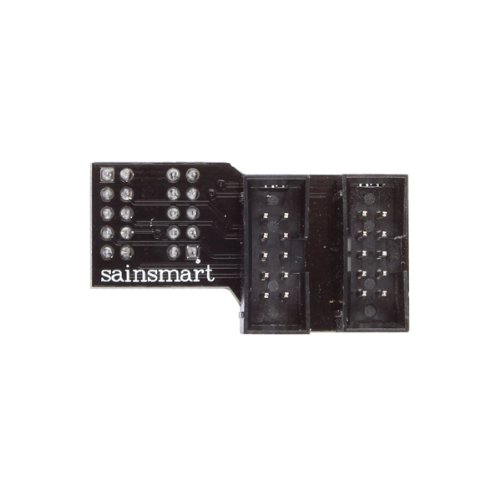
Das von Sainsmart verkaufte große LCD Display Keyboard ist ja "baugleich"...und wird mit nem passenden Adapterboard wie auf dem Foto zu sehen, angeschlossen...
Ich kann inzwischen auch über das Display die Motoren bewegen und Heizen und Temperaturen ablesen...
Nur Drucken geht weder über PC (US , noch erkennt er die SD-Card...hat das jemand schon hinbekommen ?
Peter
PS: Beim Betrachten meiens eigenen Bildes fällt mir gerade auf: Warum zum Henker verwende ich den RC2 ?!?!?
1-mal bearbeitet. Zuletzt am 26.12.13 06:52.
Auch wenn das nen alter Thread ist:

Das von Sainsmart verkaufte große LCD Display Keyboard ist ja "baugleich"...und wird mit nem passenden Adapterboard wie auf dem Foto zu sehen, angeschlossen...
Ich kann inzwischen auch über das Display die Motoren bewegen und Heizen und Temperaturen ablesen...
Nur Drucken geht weder über PC (US
, noch erkennt er die SD-Card...hat das jemand schon hinbekommen ?Peter
PS: Beim Betrachten meiens eigenen Bildes fällt mir gerade auf: Warum zum Henker verwende ich den RC2 ?!?!?
1-mal bearbeitet. Zuletzt am 26.12.13 06:52.
|
Re: Megatronics mit Smart LCD Controller 27. December 2013 00:53 |
Registrierungsdatum: 12 Jahre zuvor Beiträge: 675 |
Quote
kamphausen
Das von Sainsmart verkaufte große LCD Display Keyboard ist ja "baugleich"...?!?!?
Nein ist es nicht, es ist 3 mal langsamer als das Original in der Datenübertragung vom Controller zum Disp, und hat auch weit weniger Kontrast.
Hardwarekiller
1-mal bearbeitet. Zuletzt am 27.12.13 00:55.
|
Re: Megatronics mit Smart LCD Controller 27. December 2013 03:08 |
Registrierungsdatum: 10 Jahre zuvor Beiträge: 10 |
Ich will darauf ja nicht "Zocken"....von daher stört das nicht...und der Kontrast ist einstellbar...
Die Anzeige "RC2" kommt aus der "dogm_lcd_implementation.h" und ist wohl beim Releasewechsel vergessen worden -> Kosmetik...
Was mich mehr stört ist die Tatsache, das hier noch garnix funktioniert....aber ich hab ja Urlaub :-)
Peter
Die Anzeige "RC2" kommt aus der "dogm_lcd_implementation.h" und ist wohl beim Releasewechsel vergessen worden -> Kosmetik...
Was mich mehr stört ist die Tatsache, das hier noch garnix funktioniert....aber ich hab ja Urlaub :-)
Peter
|
Re: Megatronics mit Smart LCD Controller 02. January 2014 15:45 |
Registrierungsdatum: 12 Jahre zuvor Beiträge: 45 |
|
Re: Megatronics mit Smart LCD Controller 02. January 2014 18:31 |
Registrierungsdatum: 10 Jahre zuvor Beiträge: 10 |
Da würd ich mal auf Hardwaredefekt tippen, denn wenn er irgend was macht, scheint die Firmware ja richtig kompiliert zu sein...
Aktuelle Marlin genommen?
Meins druckt jetzt (Lag am billigen USB-Kabel...)
Aber die SD-Card geht noch immer nicht...
Auch versteh ich nicht, wie er zwischen den beiden Cardreadern unter scheidet (einer im Graphics contriller, einer auf der Megatronics V2 )
Peter
Aktuelle Marlin genommen?
Meins druckt jetzt (Lag am billigen USB-Kabel...)
Aber die SD-Card geht noch immer nicht...
Auch versteh ich nicht, wie er zwischen den beiden Cardreadern unter scheidet (einer im Graphics contriller, einer auf der Megatronics V2 )
Peter
|
Re: Megatronics mit Smart LCD Controller 03. January 2014 05:17 |
Registrierungsdatum: 11 Jahre zuvor Beiträge: 15 |
Moin,
da mein Rumba noch kabellos in meinem Basteldelta sitzt, habe ich versucht dieses FullGraphics mit dem Megatronics2 zu verkuppeln.
Ich habe es mit der neuen Repetier 0.91 gemacht und es läuft. Da ich nicht so den Plan vom Programmieren habe musste ich D53 auf dem Megatronics per Lötkolben abzweigen. Muß es für SD CSEL unbedingt D53 sein? Habe versucht andere Pins zu wählen, gab aber nur Fehler. Der Pin lässt sich aber einfach auf dem Megatronics abgreifen. Über dem Sdeinschub ist eine 4pol Steckleiste, links neben dem L von Digitalio ist eine Durchkontaktierung das ist D53.
Da ich leider keinen Adapter habe musste es mit Lochraster und Kabel gehen und es geht
so hab ich's gemacht
-Board 701, SD Support ein
-Contoller 11 auswählen
-in der ui.h die Pins dem Megatronics anpassen. Ich habe die Pins vom Megatronic verwendet LCD / Keypad / ISP und D53
ui.h Änderungen farbig
.....
#if FEATURE_CONTROLLER==2 || FEATURE_CONTROLLER==10 || FEATURE_CONTROLLER==11 // reprapdiscount smartcontroller has a sd card buildin
#undef SDCARDDETECT
#define SDCARDDETECT 63
#undef SDCARDDETECTINVERTED
#define SDCARDDETECTINVERTED false
#undef SDSUPPORT
#define SDSUPPORT true
#endif
...........
......
#if MOTHERBOARD==80 // Rumba has different pins as RAMPS!
#define BEEPER_PIN 44
#define UI_DISPLAY_RS_PIN 19
#define UI_DISPLAY_RW_PIN -1
#define UI_DISPLAY_ENABLE_PIN 42
#define UI_DISPLAY_D0_PIN 18
#define UI_DISPLAY_D1_PIN 38
#define UI_DISPLAY_D2_PIN 41
#define UI_DISPLAY_D3_PIN 40
#define UI_DISPLAY_D4_PIN 18
#define UI_DISPLAY_D5_PIN 38
#define UI_DISPLAY_D6_PIN 41
#define UI_DISPLAY_D7_PIN 40
#define UI_ENCODER_A 12
#define UI_ENCODER_B 11
#define UI_ENCODER_CLICK 43
#define UI_RESET_PIN 46
#else
#define BEEPER_PIN 42
#define UI_DISPLAY_RS_PIN 14
#define UI_DISPLAY_RW_PIN -1
#define UI_DISPLAY_ENABLE_PIN 15
#define UI_DISPLAY_D0_PIN 23
#define UI_DISPLAY_D1_PIN 25
#define UI_DISPLAY_D2_PIN 27
#define UI_DISPLAY_D3_PIN 29
#define UI_DISPLAY_D4_PIN 30
#define UI_DISPLAY_D5_PIN 25
#define UI_DISPLAY_D6_PIN 27
#define UI_DISPLAY_D7_PIN 29
#define UI_ENCODER_A 61
#define UI_ENCODER_B 59
#define UI_ENCODER_CLICK 43
#define UI_RESET_PIN 41
#endif
#endif
........
MISO,SCK,MOSI,RESET liegen auf dem ISP und brauchen (und können wohl auch) nicht geändert werden.
Damit geht das Display, die SD, der Resetknopf und der Pieper auf der Controllerplatine. Jetzt muß ich nur noch rausfinden wie ich meine anderen Buttons da mit reinbekomme und ich bestell mir noch ein FullGraphics.
Falls es einen eleganteren Weg gibt bin ich da sehr offen, ist ja nicht einfach plug&play.
hoffe mal es hilft dem Einen oder Anderen
Gruß Stefan
|
Re: Megatronics mit Smart LCD Controller 03. January 2014 10:20 |
Registrierungsdatum: 12 Jahre zuvor Beiträge: 45 |
Quote
kamphausen
Da würd ich mal auf Hardwaredefekt tippen, denn wenn er irgend was macht, scheint die Firmware ja richtig kompiliert zu sein...
Aktuelle Marlin genommen?
Meins druckt jetzt (Lag am billigen USB-Kabel...)
Aber die SD-Card geht noch immer nicht...
Auch versteh ich nicht, wie er zwischen den beiden Cardreadern unter scheidet (einer im Graphics contriller, einer auf der Megatronics V2 )
Peter
Hallo Peter!
Danke für den Tipp! Ich habe den Fehler gefunden -jetzt läuft alles! Es war tatsächlich ein Hardwarefehler - in der Adapterplatine. Unter der einen Steckerwanne hat Lötzinn einen Encoder-Pin dauerhaft gegen Masse gezogen - da kann dann wohl nix klappen. Sockel aus- und wieder eingelötet - und läuft.
SD habe ich noch nicht versucht, mache ich aber sobald alles verkabelt ist.
Gruß, Lutjanus
1-mal bearbeitet. Zuletzt am 03.01.14 10:21.
|
Re: Megatronics mit Smart LCD Controller 04. January 2014 14:35 |
Registrierungsdatum: 12 Jahre zuvor Beiträge: 45 |
So, mein SD-Leser auf der Megatronic funktioniert, der auf dem Displayboard nicht. Aber anscheinend geht es mit dem Adapter nicht:
[www.geeetech.com]
Gruß, Lutjanus
[www.geeetech.com]
Gruß, Lutjanus
|
Re: Megatronics mit Smart LCD Controller 11. January 2014 15:39 |
Registrierungsdatum: 10 Jahre zuvor Beiträge: 10 |
|
Re: Megatronics mit Smart LCD Controller 12. January 2014 15:08 |
Registrierungsdatum: 10 Jahre zuvor Beiträge: 24 |
Hallo Zusammen,
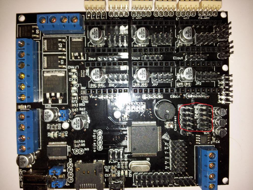
ich hab mal eine grundsätzliche Frage zu dem Adapater der LCD-Displays für das Megatronics board.
Wie genau muss ich das anstecken?
Auf der Platine sind ja einmal 2x6 Pins die mit LCD bezeichnet sind und 2x5 Pins die mit Keypad. Wenn ich den Adapter draufstecke bleiben quasi 2 Pins von LCD frei oder?
Ich frag nur deshalb, weil bei meinem bestellen Set von Sainstore.de von grundauf ein fehlerhafter Adapter für das LCD-Display mitgeliefert wurde.
Die haben auf den Adapter anstatt 2 Buchsen und 2 Stecker einfach mal 4 Stecker aufgelötet. Jetzt kann ich natürlich meine Kabel nicht anschließen.
Der Anschluss des Adapters erfolgt dann wie im Bild eingezeichnet seh ich das richtig?
Gruß Buckhunter
1-mal bearbeitet. Zuletzt am 12.01.14 15:19.
|
Re: Megatronics mit Smart LCD Controller 12. January 2014 16:05 |
Registrierungsdatum: 12 Jahre zuvor Beiträge: 45 |
|
Re: Megatronics mit Smart LCD Controller 12. January 2014 16:23 |
Registrierungsdatum: 12 Jahre zuvor Beiträge: 45 |
Quote
Buckhunter
Hallo Zusammen,
ich hab mal eine grundsätzliche Frage zu dem Adapater der LCD-Displays für das Megatronics board.
Wie genau muss ich das anstecken?
Auf der Platine sind ja einmal 2x6 Pins die mit LCD bezeichnet sind und 2x5 Pins die mit Keypad. Wenn ich den Adapter draufstecke bleiben quasi 2 Pins von LCD frei oder?
Ich frag nur deshalb, weil bei meinem bestellen Set von Sainstore.de von grundauf ein fehlerhafter Adapter für das LCD-Display mitgeliefert wurde.
Die haben auf den Adapter anstatt 2 Buchsen und 2 Stecker einfach mal 4 Stecker aufgelötet. Jetzt kann ich natürlich meine Kabel nicht anschließen.
Der Anschluss des Adapters erfolgt dann wie im Bild eingezeichnet seh ich das richtig?
Gruß Buckhunter
Ja, zwei Pins bleiben frei. Das ganze muß so aussehen:

|
Re: Megatronics mit Smart LCD Controller 13. January 2014 05:17 |
Registrierungsdatum: 10 Jahre zuvor Beiträge: 10 |
Quote
lutjanus
Quote
kamphausen
Verrätst du auch , wie du das gemacht hast?
1. Kleine SD-Karte in den Slot auf der Megatronics-Platine stecken.
2. Im Menü "Init. SD.Card" klicken
3. Im Menü "Print from SD-Card" wählen.
Öhm....
Welche Firmware? Welche settings?
Ich hab bei mir gerade noch mal alles "durchgeklingelt"...die Verbindungen scheinen in Ordnung zu sein...
Trotzdem bekomm ich mit ner Marlin 1.0 (Board 701) + SDSUPPORT definiert immer "SD Init Error"
SD-Card 1GB Fat32 formatiert...
Zugriff ist nicht möglich...
Ich werd wohl mal den 74HC4050 austauschen....
Peter
1-mal bearbeitet. Zuletzt am 13.01.14 06:41.
|
Re: Megatronics mit Smart LCD Controller 13. January 2014 16:49 |
Registrierungsdatum: 12 Jahre zuvor Beiträge: 45 |
Hi Peter!
Ich habe hier eine "handelsübliche" Marlin 1.0 drauf, wie bei Dir. Löte doch nochmal alle Anschlüsse vom 74HC4050 nach, bzw. reinige die Anschlüsse mit etwas Spiritus & Zahnbürste. Meisten ist es irgend eine Kleinigkeit (Lötzinnrest o.ä.) was Scherereien verursacht.
Viel Erfolg erstmal.
Hier ist meine Configuration.h (noch keine Parameter für Motoren etc. angepasst, aber die relevanten Dinge für die SD-Karte sind drin):
1-mal bearbeitet. Zuletzt am 13.01.14 16:53.
Ich habe hier eine "handelsübliche" Marlin 1.0 drauf, wie bei Dir. Löte doch nochmal alle Anschlüsse vom 74HC4050 nach, bzw. reinige die Anschlüsse mit etwas Spiritus & Zahnbürste. Meisten ist es irgend eine Kleinigkeit (Lötzinnrest o.ä.) was Scherereien verursacht.
Viel Erfolg erstmal.
Hier ist meine Configuration.h (noch keine Parameter für Motoren etc. angepasst, aber die relevanten Dinge für die SD-Karte sind drin):
#ifndef CONFIGURATION_H #define CONFIGURATION_H // This configuration file contains the basic settings. // Advanced settings can be found in Configuration_adv.h // BASIC SETTINGS: select your board type, temperature sensor type, axis scaling, and endstop configuration //=========================================================================== //============================= DELTA Printer =============================== //=========================================================================== // For a Delta printer rplace the configuration files wilth the files in the // example_configurations/delta directory. // // User-specified version info of this build to display in [Pronterface, etc] terminal window during // startup. Implementation of an idea by Prof Braino to inform user that any changes made to this // build by the user have been successfully uploaded into firmware. #define STRING_VERSION_CONFIG_H __DATE__ " " __TIME__ // build date and time #define STRING_CONFIG_H_AUTHOR "(none, default config)" // Who made the changes. // SERIAL_PORT selects which serial port should be used for communication with the host. // This allows the connection of wireless adapters (for instance) to non-default port pins. // Serial port 0 is still used by the Arduino bootloader regardless of this setting. #define SERIAL_PORT 0 // This determines the communication speed of the printer // This determines the communication speed of the printer #define BAUDRATE 250000 // This enables the serial port associated to the Bluetooth interface //#define BTENABLED // Enable BT interface on AT90USB devices //// The following define selects which electronics board you have. Please choose the one that matches your setup // 10 = Gen7 custom (Alfons3 Version) "https://github.com/Alfons3/Generation_7_Electronics" // 11 = Gen7 v1.1, v1.2 = 11 // 12 = Gen7 v1.3 // 13 = Gen7 v1.4 // 2 = Cheaptronic v1.0 // 20 = Sethi 3D_1 // 3 = MEGA/RAMPS up to 1.2 = 3 // 33 = RAMPS 1.3 / 1.4 (Power outputs: Extruder, Fan, Bed) // 34 = RAMPS 1.3 / 1.4 (Power outputs: Extruder0, Extruder1, Bed) // 35 = RAMPS 1.3 / 1.4 (Power outputs: Extruder, Fan, Fan) // 4 = Duemilanove w/ ATMega328P pin assignment // 5 = Gen6 // 51 = Gen6 deluxe // 6 = Sanguinololu < 1.2 // 62 = Sanguinololu 1.2 and above // 63 = Melzi // 64 = STB V1.1 // 65 = Azteeg X1 // 66 = Melzi with ATmega1284 (MaKr3d version) // 67 = Azteeg X3 // 7 = Ultimaker // 71 = Ultimaker (Older electronics. Pre 1.5.4. This is rare) // 77 = 3Drag Controller // 8 = Teensylu // 80 = Rumba // 81 = Printrboard (AT90USB1286) // 82 = Brainwave (AT90USB646) // 83 = SAV Mk-I (AT90USB1286) // 9 = Gen3+ // 70 = Megatronics // 701= Megatronics v2.0 // 702= Minitronics v1.0 // 90 = Alpha OMCA board // 91 = Final OMCA board // 301 = Rambo // 21 = Elefu Ra Board (v3) #ifndef MOTHERBOARD #define MOTHERBOARD 701 #endif // Define this to set a custom name for your generic Mendel, // #define CUSTOM_MENDEL_NAME "This Mendel" // Define this to set a unique identifier for this printer, (Used by some programs to differentiate between machines) // You can use an online service to generate a random UUID. (eg [www.uuidgenerator.net]) // #define MACHINE_UUID "00000000-0000-0000-0000-000000000000" // This defines the number of extruders #define EXTRUDERS 1 //// The following define selects which power supply you have. Please choose the one that matches your setup // 1 = ATX // 2 = X-Box 360 203Watts (the blue wire connected to PS_ON and the red wire to VCC) #define POWER_SUPPLY 1 // Define this to have the electronics keep the powersupply off on startup. If you don't know what this is leave it. // #define PS_DEFAULT_OFF //=========================================================================== //=============================Thermal Settings ============================ //=========================================================================== // //--NORMAL IS 4.7kohm PULLUP!-- 1kohm pullup can be used on hotend sensor, using correct resistor and table // //// Temperature sensor settings: // -2 is thermocouple with MAX6675 (only for sensor 0) // -1 is thermocouple with AD595 // 0 is not used // 1 is 100k thermistor - best choice for EPCOS 100k (4.7k pullup) // 2 is 200k thermistor - ATC Semitec 204GT-2 (4.7k pullup) // 3 is mendel-parts thermistor (4.7k pullup) // 4 is 10k thermistor !! do not use it for a hotend. It gives bad resolution at high temp. !! // 5 is 100K thermistor - ATC Semitec 104GT-2 (Used in ParCan & J-Head) (4.7k pullup) // 6 is 100k EPCOS - Not as accurate as table 1 (created using a fluke thermocouple) (4.7k pullup) // 7 is 100k Honeywell thermistor 135-104LAG-J01 (4.7k pullup) // 71 is 100k Honeywell thermistor 135-104LAF-J01 (4.7k pullup) // 8 is 100k 0603 SMD Vishay NTCS0603E3104FXT (4.7k pullup) // 9 is 100k GE Sensing AL03006-58.2K-97-G1 (4.7k pullup) // 10 is 100k RS thermistor 198-961 (4.7k pullup) // 60 is 100k Maker's Tool Works Kapton Bed Thermister // // 1k ohm pullup tables - This is not normal, you would have to have changed out your 4.7k for 1k // (but gives greater accuracy and more stable PID) // 51 is 100k thermistor - EPCOS (1k pullup) // 52 is 200k thermistor - ATC Semitec 204GT-2 (1k pullup) // 55 is 100k thermistor - ATC Semitec 104GT-2 (Used in ParCan & J-Head) (1k pullup) #define TEMP_SENSOR_0 -1 #define TEMP_SENSOR_1 -1 #define TEMP_SENSOR_2 0 #define TEMP_SENSOR_BED 0 // This makes temp sensor 1 a redundant sensor for sensor 0. If the temperatures difference between these sensors is to high the print will be aborted. //#define TEMP_SENSOR_1_AS_REDUNDANT #define MAX_REDUNDANT_TEMP_SENSOR_DIFF 10 // Actual temperature must be close to target for this long before M109 returns success #define TEMP_RESIDENCY_TIME 10 // (seconds) #define TEMP_HYSTERESIS 3 // (degC) range of +/- temperatures considered "close" to the target one #define TEMP_WINDOW 1 // (degC) Window around target to start the residency timer x degC early. // The minimal temperature defines the temperature below which the heater will not be enabled It is used // to check that the wiring to the thermistor is not broken. // Otherwise this would lead to the heater being powered on all the time. #define HEATER_0_MINTEMP 5 #define HEATER_1_MINTEMP 5 #define HEATER_2_MINTEMP 5 #define BED_MINTEMP 5 // When temperature exceeds max temp, your heater will be switched off. // This feature exists to protect your hotend from overheating accidentally, but *NOT* from thermistor short/failure! // You should use MINTEMP for thermistor short/failure protection. #define HEATER_0_MAXTEMP 275 #define HEATER_1_MAXTEMP 275 #define HEATER_2_MAXTEMP 275 #define BED_MAXTEMP 150 // If your bed has low resistance e.g. .6 ohm and throws the fuse you can duty cycle it to reduce the // average current. The value should be an integer and the heat bed will be turned on for 1 interval of // HEATER_BED_DUTY_CYCLE_DIVIDER intervals. //#define HEATER_BED_DUTY_CYCLE_DIVIDER 4 // PID settings: // Comment the following line to disable PID and enable bang-bang. #define PIDTEMP #define BANG_MAX 255 // limits current to nozzle while in bang-bang mode; 255=full current #define PID_MAX 255 // limits current to nozzle while PID is active (see PID_FUNCTIONAL_RANGE below); 255=full current #ifdef PIDTEMP //#define PID_DEBUG // Sends debug data to the serial port. //#define PID_OPENLOOP 1 // Puts PID in open loop. M104/M140 sets the output power from 0 to PID_MAX #define PID_FUNCTIONAL_RANGE 10 // If the temperature difference between the target temperature and the actual temperature // is more then PID_FUNCTIONAL_RANGE then the PID will be shut off and the heater will be set to min/max. #define PID_INTEGRAL_DRIVE_MAX 255 //limit for the integral term #define K1 0.95 //smoothing factor within the PID #define PID_dT ((16.0 * 8.0)/(F_CPU / 64.0 / 256.0)) //sampling period of the temperature routine // If you are using a preconfigured hotend then you can use one of the value sets by uncommenting it // Ultimaker #define DEFAULT_Kp 22.2 #define DEFAULT_Ki 1.08 #define DEFAULT_Kd 114 // Makergear // #define DEFAULT_Kp 7.0 // #define DEFAULT_Ki 0.1 // #define DEFAULT_Kd 12 // Mendel Parts V9 on 12V // #define DEFAULT_Kp 63.0 // #define DEFAULT_Ki 2.25 // #define DEFAULT_Kd 440 #endif // PIDTEMP // Bed Temperature Control // Select PID or bang-bang with PIDTEMPBED. If bang-bang, BED_LIMIT_SWITCHING will enable hysteresis // // Uncomment this to enable PID on the bed. It uses the same frequency PWM as the extruder. // If your PID_dT above is the default, and correct for your hardware/configuration, that means 7.689Hz, // which is fine for driving a square wave into a resistive load and does not significantly impact you FET heating. // This also works fine on a Fotek SSR-10DA Solid State Relay into a 250W heater. // If your configuration is significantly different than this and you don't understand the issues involved, you probably // shouldn't use bed PID until someone else verifies your hardware works. // If this is enabled, find your own PID constants below. //#define PIDTEMPBED // //#define BED_LIMIT_SWITCHING // This sets the max power delivered to the bed, and replaces the HEATER_BED_DUTY_CYCLE_DIVIDER option. // all forms of bed control obey this (PID, bang-bang, bang-bang with hysteresis) // setting this to anything other than 255 enables a form of PWM to the bed just like HEATER_BED_DUTY_CYCLE_DIVIDER did, // so you shouldn't use it unless you are OK with PWM on your bed. (see the comment on enabling PIDTEMPBED) #define MAX_BED_POWER 255 // limits duty cycle to bed; 255=full current #ifdef PIDTEMPBED //120v 250W silicone heater into 4mm borosilicate (MendelMax 1.5+) //from FOPDT model - kp=.39 Tp=405 Tdead=66, Tc set to 79.2, aggressive factor of .15 (vs .1, 1, 10) #define DEFAULT_bedKp 10.00 #define DEFAULT_bedKi .023 #define DEFAULT_bedKd 305.4 //120v 250W silicone heater into 4mm borosilicate (MendelMax 1.5+) //from pidautotune // #define DEFAULT_bedKp 97.1 // #define DEFAULT_bedKi 1.41 // #define DEFAULT_bedKd 1675.16 // FIND YOUR OWN: "M303 E-1 C8 S90" to run autotune on the bed at 90 degreesC for 8 cycles. #endif // PIDTEMPBED //this prevents dangerous Extruder moves, i.e. if the temperature is under the limit //can be software-disabled for whatever purposes by #define PREVENT_DANGEROUS_EXTRUDE //if PREVENT_DANGEROUS_EXTRUDE is on, you can still disable (uncomment) very long bits of extrusion separately. #define PREVENT_LENGTHY_EXTRUDE #define EXTRUDE_MINTEMP 170 #define EXTRUDE_MAXLENGTH (X_MAX_LENGTH+Y_MAX_LENGTH) //prevent extrusion of very large distances. //=========================================================================== //=============================Mechanical Settings=========================== //=========================================================================== // Uncomment the following line to enable CoreXY kinematics // #define COREXY // coarse Endstop Settings #define ENDSTOPPULLUPS // Comment this out (using // at the start of the line) to disable the endstop pullup resistors #ifndef ENDSTOPPULLUPS // fine Enstop settings: Individual Pullups. will be ignored if ENDSTOPPULLUPS is defined // #define ENDSTOPPULLUP_XMAX // #define ENDSTOPPULLUP_YMAX // #define ENDSTOPPULLUP_ZMAX // #define ENDSTOPPULLUP_XMIN // #define ENDSTOPPULLUP_YMIN // #define ENDSTOPPULLUP_ZMIN #endif #ifdef ENDSTOPPULLUPS #define ENDSTOPPULLUP_XMAX #define ENDSTOPPULLUP_YMAX #define ENDSTOPPULLUP_ZMAX #define ENDSTOPPULLUP_XMIN #define ENDSTOPPULLUP_YMIN #define ENDSTOPPULLUP_ZMIN #endif // The pullups are needed if you directly connect a mechanical endswitch between the signal and ground pins. const bool X_MIN_ENDSTOP_INVERTING = true; // set to true to invert the logic of the endstop. const bool Y_MIN_ENDSTOP_INVERTING = true; // set to true to invert the logic of the endstop. const bool Z_MIN_ENDSTOP_INVERTING = true; // set to true to invert the logic of the endstop. const bool X_MAX_ENDSTOP_INVERTING = true; // set to true to invert the logic of the endstop. const bool Y_MAX_ENDSTOP_INVERTING = true; // set to true to invert the logic of the endstop. const bool Z_MAX_ENDSTOP_INVERTING = true; // set to true to invert the logic of the endstop. //#define DISABLE_MAX_ENDSTOPS //#define DISABLE_MIN_ENDSTOPS // Disable max endstops for compatibility with endstop checking routine #if defined(COREXY) && !defined(DISABLE_MAX_ENDSTOPS) #define DISABLE_MAX_ENDSTOPS #endif // For Inverting Stepper Enable Pins (Active Low) use 0, Non Inverting (Active High) use 1 #define X_ENABLE_ON 0 #define Y_ENABLE_ON 0 #define Z_ENABLE_ON 0 #define E_ENABLE_ON 0 // For all extruders // Disables axis when it's not being used. #define DISABLE_X false #define DISABLE_Y false #define DISABLE_Z false #define DISABLE_E false // For all extruders #define INVERT_X_DIR true // for Mendel set to false, for Orca set to true #define INVERT_Y_DIR false // for Mendel set to true, for Orca set to false #define INVERT_Z_DIR true // for Mendel set to false, for Orca set to true #define INVERT_E0_DIR false // for direct drive extruder v9 set to true, for geared extruder set to false #define INVERT_E1_DIR false // for direct drive extruder v9 set to true, for geared extruder set to false #define INVERT_E2_DIR false // for direct drive extruder v9 set to true, for geared extruder set to false // ENDSTOP SETTINGS: // Sets direction of endstops when homing; 1=MAX, -1=MIN #define X_HOME_DIR -1 #define Y_HOME_DIR -1 #define Z_HOME_DIR -1 #define min_software_endstops true // If true, axis won't move to coordinates less than HOME_POS. #define max_software_endstops true // If true, axis won't move to coordinates greater than the defined lengths below. // Travel limits after homing #define X_MAX_POS 205 #define X_MIN_POS 0 #define Y_MAX_POS 205 #define Y_MIN_POS 0 #define Z_MAX_POS 200 #define Z_MIN_POS 0 #define X_MAX_LENGTH (X_MAX_POS - X_MIN_POS) #define Y_MAX_LENGTH (Y_MAX_POS - Y_MIN_POS) #define Z_MAX_LENGTH (Z_MAX_POS - Z_MIN_POS) //============================= Bed Auto Leveling =========================== //#define ENABLE_AUTO_BED_LEVELING // Delete the comment to enable (remove // at the start of the line) #ifdef ENABLE_AUTO_BED_LEVELING // these are the positions on the bed to do the probing #define LEFT_PROBE_BED_POSITION 15 #define RIGHT_PROBE_BED_POSITION 170 #define BACK_PROBE_BED_POSITION 180 #define FRONT_PROBE_BED_POSITION 20 // these are the offsets to the prob relative to the extruder tip (Hotend - Probe) #define X_PROBE_OFFSET_FROM_EXTRUDER -25 #define Y_PROBE_OFFSET_FROM_EXTRUDER -29 #define Z_PROBE_OFFSET_FROM_EXTRUDER -12.35 #define Z_RAISE_BEFORE_HOMING 4 // (in mm) Raise Z before homing (G28) for Probe Clearance. // Be sure you have this distance over your Z_MAX_POS in case #define XY_TRAVEL_SPEED 8000 // X and Y axis travel speed between probes, in mm/min #define Z_RAISE_BEFORE_PROBING 15 //How much the extruder will be raised before traveling to the first probing point. #define Z_RAISE_BETWEEN_PROBINGS 5 //How much the extruder will be raised when traveling from between next probing points //If defined, the Probe servo will be turned on only during movement and then turned off to avoid jerk //The value is the delay to turn the servo off after powered on - depends on the servo speed; 300ms is good value, but you can try lower it. // You MUST HAVE the SERVO_ENDSTOPS defined to use here a value higher than zero otherwise your code will not compile. // #define PROBE_SERVO_DEACTIVATION_DELAY 300 //If you have enabled the Bed Auto Levelling and are using the same Z Probe for Z Homing, //it is highly recommended you let this Z_SAFE_HOMING enabled!!! #define Z_SAFE_HOMING // This feature is meant to avoid Z homing with probe outside the bed area. // When defined, it will: // - Allow Z homing only after X and Y homing AND stepper drivers still enabled // - If stepper drivers timeout, it will need X and Y homing again before Z homing // - Position the probe in a defined XY point before Z Homing when homing all axis (G28) // - Block Z homing only when the probe is outside bed area. #ifdef Z_SAFE_HOMING #define Z_SAFE_HOMING_X_POINT (X_MAX_LENGTH/2) // X point for Z homing when homing all axis (G28) #define Z_SAFE_HOMING_Y_POINT (Y_MAX_LENGTH/2) // Y point for Z homing when homing all axis (G28) #endif // with accurate bed leveling, the bed is sampled in a ACCURATE_BED_LEVELING_POINTSxACCURATE_BED_LEVELING_POINTS grid and least squares solution is calculated // Note: this feature occupies 10'206 byte #define ACCURATE_BED_LEVELING #ifdef ACCURATE_BED_LEVELING // I wouldn't see a reason to go above 3 (=9 probing points on the bed) #define ACCURATE_BED_LEVELING_POINTS 2 #endif #endif // The position of the homing switches //#define MANUAL_HOME_POSITIONS // If defined, MANUAL_*_HOME_POS below will be used //#define BED_CENTER_AT_0_0 // If defined, the center of the bed is at (X=0, Y=0) //Manual homing switch locations: // For deltabots this means top and center of the cartesian print volume. #define MANUAL_X_HOME_POS 0 #define MANUAL_Y_HOME_POS 0 #define MANUAL_Z_HOME_POS 0 //#define MANUAL_Z_HOME_POS 402 // For delta: Distance between nozzle and print surface after homing. //// MOVEMENT SETTINGS #define NUM_AXIS 4 // The axis order in all axis related arrays is X, Y, Z, E #define HOMING_FEEDRATE {50*60, 50*60, 4*60, 0} // set the homing speeds (mm/min) // default settings #define DEFAULT_AXIS_STEPS_PER_UNIT {78.7402,78.7402,200.0*8/3,760*1.1} // default steps per unit for Ultimaker #define DEFAULT_MAX_FEEDRATE {500, 500, 5, 25} // (mm/sec) #define DEFAULT_MAX_ACCELERATION {9000,9000,100,10000} // X, Y, Z, E maximum start speed for accelerated moves. E default values are good for skeinforge 40+, for older versions raise them a lot. #define DEFAULT_ACCELERATION 3000 // X, Y, Z and E max acceleration in mm/s^2 for printing moves #define DEFAULT_RETRACT_ACCELERATION 3000 // X, Y, Z and E max acceleration in mm/s^2 for retracts // Offset of the extruders (uncomment if using more than one and relying on firmware to position when changing). // The offset has to be X=0, Y=0 for the extruder 0 hotend (default extruder). // For the other hotends it is their distance from the extruder 0 hotend. // #define EXTRUDER_OFFSET_X {0.0, 20.00} // (in mm) for each extruder, offset of the hotend on the X axis // #define EXTRUDER_OFFSET_Y {0.0, 5.00} // (in mm) for each extruder, offset of the hotend on the Y axis // The speed change that does not require acceleration (i.e. the software might assume it can be done instantaneously) #define DEFAULT_XYJERK 20.0 // (mm/sec) #define DEFAULT_ZJERK 0.4 // (mm/sec) #define DEFAULT_EJERK 5.0 // (mm/sec) //=========================================================================== //=============================Additional Features=========================== //=========================================================================== // EEPROM // the microcontroller can store settings in the EEPROM, e.g. max velocity... // M500 - stores paramters in EEPROM // M501 - reads parameters from EEPROM (if you need reset them after you changed them temporarily). // M502 - reverts to the default "factory settings". You still need to store them in EEPROM afterwards if you want to. //define this to enable eeprom support //#define EEPROM_SETTINGS //to disable EEPROM Serial responses and decrease program space by ~1700 byte: comment this out: // please keep turned on if you can. //#define EEPROM_CHITCHAT // Preheat Constants #define PLA_PREHEAT_HOTEND_TEMP 180 #define PLA_PREHEAT_HPB_TEMP 70 #define PLA_PREHEAT_FAN_SPEED 255 // Insert Value between 0 and 255 #define ABS_PREHEAT_HOTEND_TEMP 240 #define ABS_PREHEAT_HPB_TEMP 100 #define ABS_PREHEAT_FAN_SPEED 255 // Insert Value between 0 and 255 //LCD and SD support //#define ULTRA_LCD //general lcd support, also 16x2 //#define DOGLCD // Support for SPI LCD 128x64 (Controller ST7565R graphic Display Family) //#define SDSUPPORT // Enable SD Card Support in Hardware Console //#define SDSLOW // Use slower SD transfer mode (not normally needed - uncomment if you're getting volume init error) //#define ENCODER_PULSES_PER_STEP 1 // Increase if you have a high resolution encoder //#define ENCODER_STEPS_PER_MENU_ITEM 5 // Set according to ENCODER_PULSES_PER_STEP or your liking //#define ULTIMAKERCONTROLLER //as available from the ultimaker online store. //#define ULTIPANEL //the ultipanel as on thingiverse // The MaKr3d Makr-Panel with graphic controller and SD support // [reprap.org] //#define MAKRPANEL // The RepRapDiscount Smart Controller (white PC
1-mal bearbeitet. Zuletzt am 13.01.14 16:53.
|
Re: Megatronics mit Smart LCD Controller 23. January 2014 10:09 |
Registrierungsdatum: 10 Jahre zuvor Beiträge: 10 |
|
Re: Megatronics mit Smart LCD Controller 23. January 2014 14:09 |
Registrierungsdatum: 12 Jahre zuvor Beiträge: 45 |
Klar, kein Problem, schick Deine Adresse rüber. Bei meiner Marlin V1.0 sind nur noch keine Werte für die Schritte der einzelnen Achsen drin, da der Drucker an den die Megatronic soll noch nicht zusammengebaut ist. Das mußt Du dann an Deinen Drucker anpassen.
Gruß,
Lutjanus
Gruß,
Lutjanus
Quote
kamphausen
Sorry, aber das läuft bei mir mit deiner config nicht...
Wäre schön, wenn Du mir mal dein komplettes Marlin, wie Du es momentan laufen hast, in nen ZIP-File packen kannst....ich schick Dri meine Mailadress per PN....
Peter
|
Re: Megatronics mit Smart LCD Controller 21. February 2014 16:39 |
Registrierungsdatum: 10 Jahre zuvor Beiträge: 10 |
Grrrrr..
74HC4050 ist getauscht..
Alle Leitungen durchgemessen und ok..
Die Drecks SDcard auf der Megatronics läßt sich nicht ansprechen...2GB Fat32 formatiert...nen paar *.gcode sind auch schon drauf...
Konfiguration: einzelne Megatronics V2 ohne irgend was, Board 701 in aktueller Marlin ohne sonst irgend was gewählt...
Dreck Dreck Dreck Dreck Dreck...
Peter
1-mal bearbeitet. Zuletzt am 23.02.14 03:06.
|
Re: Megatronics mit Smart LCD Controller 24. February 2014 03:53 |
Registrierungsdatum: 11 Jahre zuvor Beiträge: 69 |
|
Re: Megatronics mit Smart LCD Controller 27. February 2014 06:01 |
Registrierungsdatum: 10 Jahre zuvor Beiträge: 10 |
So hatte ich das verstanden....
Mosi, Miso etc. sind ja eh nur ein mal vorhanden und D53 ist auch fertig geroutet...
Hab schon inder Firmware mal testhlaber den Speed runter gesetzt, bekomm aber immer noch den gleichen Fehler...
Im REPETIER-Host keine verbindung und im Log SD-INIT failed...
Peter
(Am FullGraphics-Controller hat´s natürlich auch nicht funktioniert....den hab ich jetzt aber erst mal zum reduzieren der Fehlermöglichkeiten abgebaut...)
|
Re: Megatronics mit Smart LCD Controller 15. March 2014 12:58 |
Registrierungsdatum: 12 Jahre zuvor Beiträge: 45 |
Ich habe den SD-Kartenslot auf der LCD-Platine jetzt auch am laufen, und bin wie folgt vorgegangen:
Um den Buzzer (Lautsprecher) auf der Display-Platine zu aktivieren ist lediglich ein Kabel (Lackdraht) auf der Adapterplatine erforderlich. Hier ist Pin 1 des Keyboard-Anschlusses auf Pin 1 des linken Flachbandkabel-Ansclusses zu legen. Dann noch in der Firmware (pins.h) den Buzzer von Port 64 auf 65 ändern und es piepst von der Displayplatine.
- ICSP-Pfostenleise ausgelötet
- Neue Pfostenleiste mit 2x4 Pins eingelötet, vorher zwei Pins umgebogen (da es dafür keine Löcher in der Platine gibt)
- Signal D53 von Pin 7 des 74HC4050 auf die Vorderseite bringen (Lackdraht) und an einem der neuen Pins vom ICSP Port anlöten
- Pins vom ICSP Port mit Adapterplatine des Displays verbinden (s. Foto)


Um den Buzzer (Lautsprecher) auf der Display-Platine zu aktivieren ist lediglich ein Kabel (Lackdraht) auf der Adapterplatine erforderlich. Hier ist Pin 1 des Keyboard-Anschlusses auf Pin 1 des linken Flachbandkabel-Ansclusses zu legen. Dann noch in der Firmware (pins.h) den Buzzer von Port 64 auf 65 ändern und es piepst von der Displayplatine.
|
Re: Megatronics mit Smart LCD Controller 15. June 2014 08:32 |
Registrierungsdatum: 10 Jahre zuvor Beiträge: 2 |

|
Re: Megatronics mit Smart LCD Controller 16. July 2014 10:16 |
Registrierungsdatum: 9 Jahre zuvor Beiträge: 2 |
|
Re: Megatronics mit Smart LCD Controller 16. July 2014 15:05 |
Registrierungsdatum: 12 Jahre zuvor Beiträge: 45 |
Hi Simon!
Die Nummerierung entspricht dem Standard für zweirreihige Pfostenleisten. Der eckige Pin ist 1, auf der kurzen Seite daneben die zwei. Unter der 1 befindet sich die 3, auf der kurzen Seite daneben die 4, usw...
Hier ist ein Foto zur Verdeutlichung Nummerierung Pfostenleiste. Die ist zwar etwas länger, aber das Prinzip ist identisch.
So und jetzt viel Spaß beim Umbau!
Lutjanus
|
Re: Megatronics mit Smart LCD Controller 17. July 2014 03:35 |
Registrierungsdatum: 9 Jahre zuvor Beiträge: 2 |
|
Re: Megatronics mit Smart LCD Controller 16. March 2015 05:37 |
Registrierungsdatum: 9 Jahre zuvor Beiträge: 101 |
Hallo,
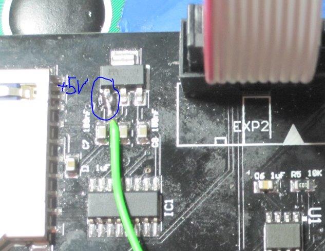
hier meine Lösung...
und es lag doch an der Hardware ;-) Ok wer sainsmart kauft muss damit rechnen.
Es ist tatsächlich so gewesen das der SD Karten Slot keine 3.3V erhalten hat.
Der Hammer ist aber bei der Leiterbahn für den Spannungswandler 5-->3.3V kamen keine 5V an.
Habe also eine Brücke vom LCD PIN 2 dort zum Regler (siehe Bild) gelegt.
Und siehe da, Karte erkannt.
Jetzt schnell ein Druck gemacht. Der ging aber völlig in die Hose, der Drucker machte seltsame Sachen.
Habe herausgefunden das meine SD Karte wohl zu langsam war. Na egal jetzt steckt eine 8 !! GB FAT32 SD Karte
drin und der Drucker rennt wie verrückt.
D A N K E
Peik
_________________________________________________________________________________________________
Bevor ich hier eine Frage stelle, habe ich hoffentlich gründlich recherchiert. Grundsätzlich versuche ich selbst Lösungen zu finden, nur manchmal bekomme ich es nicht hin und noch mehr graue Haare stehen mir nicht. Also seht es mir nach, wenn ich dann doch mal eine Frage stelle und über jede einzelne Antwort freue und bedanke ich mich hier nochmals.
|
Re: Megatronics mit Smart LCD Controller 12. August 2015 05:07 |
Registrierungsdatum: 9 Jahre zuvor Beiträge: 4 |

|
Re: Megatronics mit Smart LCD Controller 07. November 2015 08:47 |
Registrierungsdatum: 8 Jahre zuvor Beiträge: 3 |
If you got an megatronics 3.0 the adapter wil not work because it blocks out the temperature ports. The good news is you can get your Full Graphic Smart Controller completely to work with just rewiring the flat cables to some pin header connectors (dupont) and some changes to the Marlin 1.1.0 (rc-2). No soldering required.
Wiring scheme for megatronics 3.0 with Full Graphic Smart Controller:
exp1 pin 1 --> Keypad pin 10
exp1 pin 2 --> Keypad pin 4
exp1 pin 3 --> LCD pin 6
exp1 pin 4 --> LCD pin 4
exp1 pin 5 --> LCD pin 7
exp1 pin 6 --> LCD pin 8
exp1 pin 7 --> LCD pin 9
exp1 pin 8 --> LCD pin 10
exp1 pin 9 --> LCD pin 1
exp1 pin 10 --> LCD pin 2
exp2 pin 1 --> SDOut pin 3
exp2 pin 2 --> SDOut pin 5
exp2 pin 3 --> Keypad pin 5
exp2 pin 4 --> SDout 6
exp2 pin 5 --> keypad pin 3
exp2 pin 6 --> SDout pin 4
exp2 pin 7 --> SDOut pin 2
exp2 pin 8 --> ICSP pin 5
exp2 pin 9 --> Keypad 2
exp2 pin 10 --> (ICSP 6)
Changes to Marlin 1.1.0 RC2
Configuration.h
....
//#define ULTRA_LCD //general LCD support, also 16x2
//#define DOGLCD // Support for SPI LCD 128x64 (Controller ST7565R graphic Display Family)
#define SDSUPPORT // Enable SD Card Support in Hardware Console
// Changed behaviour! If you need SDSUPPORT uncomment it!
....
// The RepRapDiscount FULL GRAPHIC Smart Controller (quadratic white PC
// [reprap.org]
//
// ==> REMEMBER TO INSTALL U8glib to your ARDUINO library folder: [code.google.com]
#define REPRAP_DISCOUNT_FULL_GRAPHIC_SMART_CONTROLLER
pins_MEGATRONICS_3.h
...
#define TEMP_BED_PIN (TEMP_SENSOR_BED == -1 ? 8 : 14) // ANALOG NUMBERING
#ifndef REPRAP_DISCOUNT_FULL_GRAPHIC_SMART_CONTROLLER
#define BEEPER_PIN 61
#else
#define BEEPER_PIN 36
#endif
#define LCD_PINS_RS 32
...
#define BLEN_A 0
#ifndef REPRAP_DISCOUNT_FULL_GRAPHIC_SMART_CONTROLLER
#define SD_DETECT_PIN -1 // Megatronics doesn't use this
#else
#define SD_DETECT_PIN 56 // Megatronics with Full Graphic Smart Controller does use it
#endif
|
Re: Megatronics mit Smart LCD Controller 20. November 2015 06:58 |
Registrierungsdatum: 8 Jahre zuvor Beiträge: 11 |
When USB connected i have on pin 2 4.87V and pin 3 3.3V , When usb remove and board only connect to 12V power supply pin 2 is 3.3V (Why?) and pin 3 3.3V
LCD working only when usb connect and pin 2 has 4.8V , but with out usb pin 2 receive 3.3V and LCD not working only backlight of LCD turn on when push keypad
Im not electronic man but im sure the problem becomes from pin 2 how can i deliver 4.8V to pin 2 when usb not connected

Also please have look on Pic2
Again with USB Connect it shows 5V and with out USB and only with 12V power supply it shows 3.3V
PLEASE HELP ME HOW TO DELIVER 5V TO PINS AND RESOLVE THIS PROBLEM , im sure if i can deliver 5V to the pins even with out USB ,LCD will work fine and can to use printer with out laptop or desktop

LCD working only when usb connect and pin 2 has 4.8V , but with out usb pin 2 receive 3.3V and LCD not working only backlight of LCD turn on when push keypad
Im not electronic man but im sure the problem becomes from pin 2 how can i deliver 4.8V to pin 2 when usb not connected
Also please have look on Pic2
Again with USB Connect it shows 5V and with out USB and only with 12V power supply it shows 3.3V
PLEASE HELP ME HOW TO DELIVER 5V TO PINS AND RESOLVE THIS PROBLEM , im sure if i can deliver 5V to the pins even with out USB ,LCD will work fine and can to use printer with out laptop or desktop
In diesem Forum dürfen leider nur registrierte Teilnehmer schreiben.