Questions on RAMPS assembling
Posted by GammaRay
|
Questions on RAMPS assembling May 24, 2011 02:56PM |
Registered: 12 years ago Posts: 6 |
Hi All!
I'm currently assembling some RAMPSs but I have the Version 1.2 PCBs and the Wikipage only shows images of an older revision. I also found images of complete 1.2 shields, but they didn't help too much either. So few questions came up during soldering the first shield:
1. This maybe obsolete because I already soldered this part but just to be sure: where should be + for the 100nF capacitor C4? By looking on the bottom layer of the PCB I chose to orient + to the left if looking on it this way: capacitors on RAMPS (additional: find the typo on the image by comparing capacities written on the PCB to the overlays). Also step 3 in the instruction list doesn't mention anything on polarity.
2. What about the diode D1? I read the description multiple times but am still inconclusive. I plan to only use 12V power supplys, so no damage soldering it, but are there any other dis-/advantages using D1 (except the need for buying it :-) ) ?
After completing the first shield I wanted to test it, but I still need the polulus and stepper motors, so this is some weeks in the future. When this is done I plan to update the Wiki with some v1.2 images and corrections (with non-stackable headers like here: fully assembled version 1.2 RAMPS, which helped with C5 & C8 polarity. Also why is C4 mentioned again in step 9 of the instructions?)
Thanks for your help,
GammaRay
|
Re: Questions on RAMPS assembling May 24, 2011 04:04PM |
Registered: 13 years ago Posts: 226 |
Hi,
I had exactly the same thoughts as you as I built my RAMPs v1.2 - and I completely forgot that I planned to update the Wiki with images of the newer version too. I will put this in my todo list, unless you feel a desire to update it yourself later Here is a photo of my completed (and working) board...
To answer your questions ..
1. Does this capacitor have a polarity?! I just had a look on the board itself and couldn't see one.
2. As you can see in the image, I added the diode. I'm using a 12v supply and so far all is ok.
Hope that helps.
------------------------------------------
garyhodgson.com/reprap | reprap.development-tracker.info | thingtracker.net
I had exactly the same thoughts as you as I built my RAMPs v1.2 - and I completely forgot that I planned to update the Wiki with images of the newer version too. I will put this in my todo list, unless you feel a desire to update it yourself later
Here is a photo of my completed (and working) board...
To answer your questions ..
1. Does this capacitor have a polarity?! I just had a look on the board itself and couldn't see one.
2. As you can see in the image, I added the diode. I'm using a 12v supply and so far all is ok.
Hope that helps.
------------------------------------------
garyhodgson.com/reprap | reprap.development-tracker.info | thingtracker.net
|
Re: Questions on RAMPS assembling May 24, 2011 08:09PM |
Registered: 16 years ago Posts: 824 |
The diode is there in case you have other accesories to add, like SD card, or maybe LCD. If this is not in the immediate future, I would leave it off, as it exposes the Arduino to potential for damage from voltage spikes from a faulty power source.
The C4 cap does not have polarity. The black ones that look like cans do. You will know if you connect it the wrong way because it will explode violently.
The C4 cap does not have polarity. The black ones that look like cans do. You will know if you connect it the wrong way because it will explode violently.
|
Re: Questions on RAMPS assembling May 25, 2011 12:59PM |
Registered: 12 years ago Posts: 6 |
Thanks for the quick response.
D1:
SD support for RAMPS seems to be not far down the road. I would really like that, so the PC can switched off during printing. Also transmission rates and hanging PCs are no issue for SD printing, so I will put D1 in.
C4:
The component I wanted to use has following values: 100nF, 35V and looks exactly like this:
The + on the capacitor and the longer pin indicates a polarity. Do I have a wrong part? I know that 35V isn't needed here, but that shouldn't matter as long as it is more than 12 V. By looking at the bottom of the PCB you can see, that C4 is on the same "PCB routes" as C6, so I put + to the left.
GammaRay
D1:
SD support for RAMPS seems to be not far down the road. I would really like that, so the PC can switched off during printing. Also transmission rates and hanging PCs are no issue for SD printing, so I will put D1 in.
C4:
The component I wanted to use has following values: 100nF, 35V and looks exactly like this:

The + on the capacitor and the longer pin indicates a polarity. Do I have a wrong part? I know that 35V isn't needed here, but that shouldn't matter as long as it is more than 12 V. By looking at the bottom of the PCB you can see, that C4 is on the same "PCB routes" as C6, so I put + to the left.
GammaRay
|
Re: Questions on RAMPS assembling July 03, 2011 10:35AM |
Registered: 12 years ago Posts: 57 |
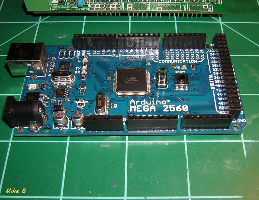
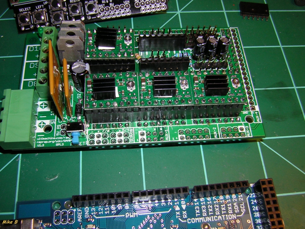
Ok now may i have more please sir? A photo of RAMPS 1.3(Rep Rap Arduino Mega Pololu Shield) like the above 1.2 and any hints or tips as i just turned off my iron as the wiki is not clear. I thank you in advance..
if you can not.. i understand but a hint as to where i might see a photo will help for now.
if you can not.. i understand but a hint as to where i might see a photo will help for now.
|
Re: Questions on RAMPS assembling July 03, 2011 01:00PM |
Registered: 12 years ago Posts: 6 |
|
Re: Questions on RAMPS assembling July 03, 2011 10:01PM |
Registered: 16 years ago Posts: 824 |
|
Re: Questions on RAMPS assembling July 15, 2011 11:12PM |
Registered: 12 years ago Posts: 57 |
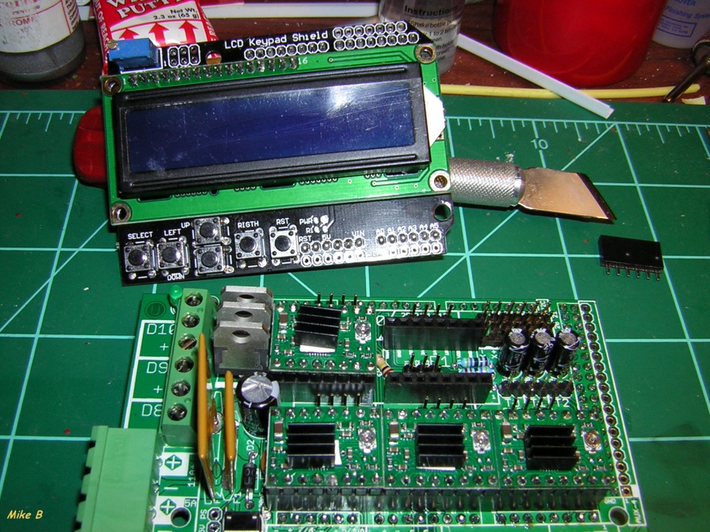
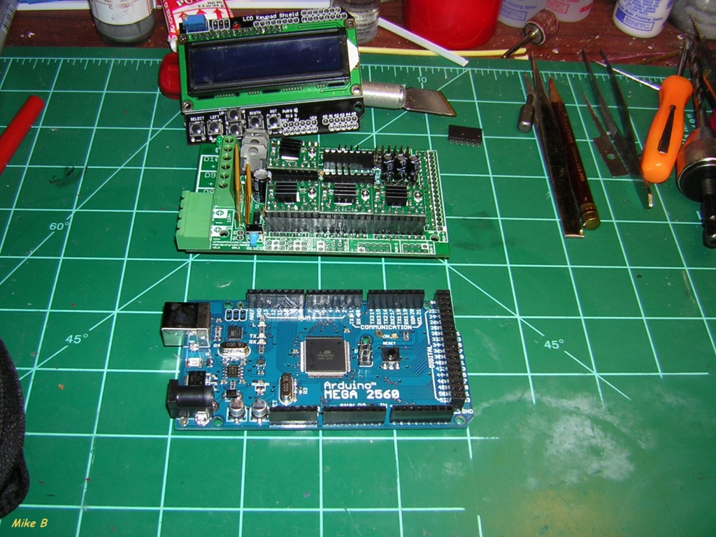
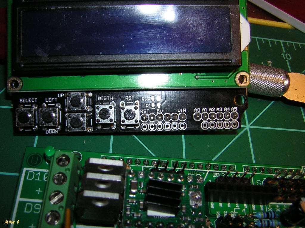
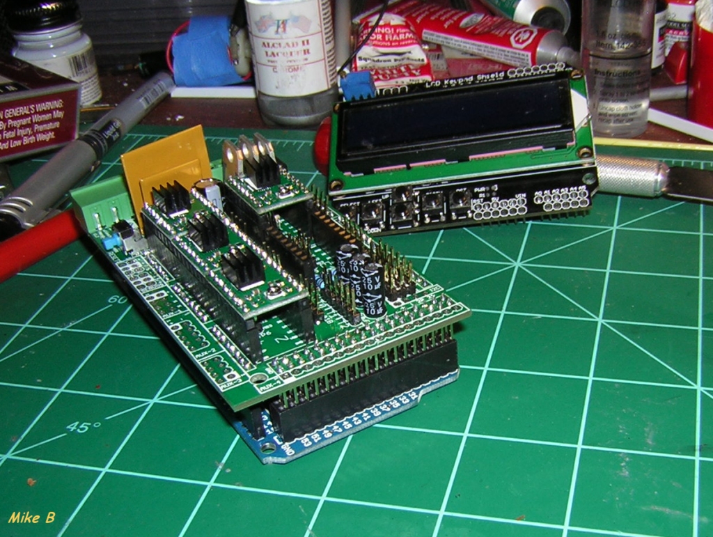
i have a LCD key board and did install the diode and plan to add an SD card can i do both? or only one or the other.
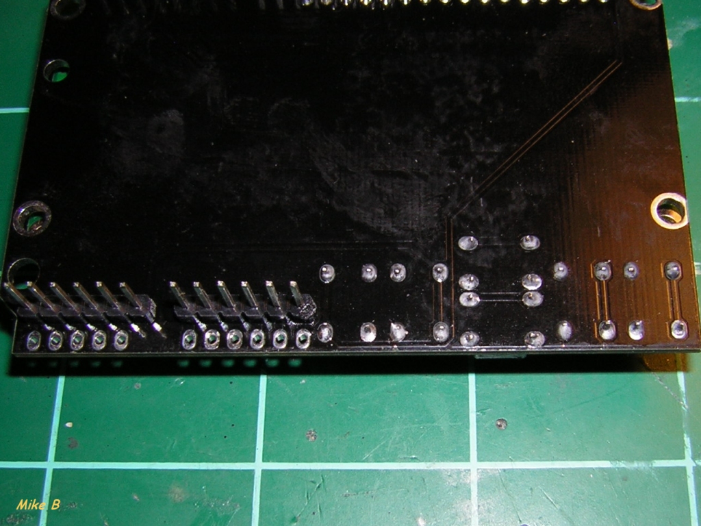
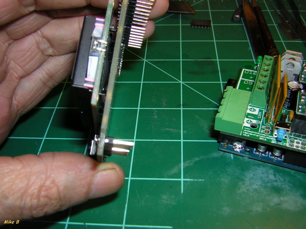
i see that i will have to hack the LCD in between the RAMPS and The Arduino but have not seen a example. might some one direct me to the right group
or thread.
and i used the picks from Finland to build my 1.3 ramps kit.
power from USB? or my power supply ? 500 watt power supply enough? 2 rails12V@18A each +5V@25A
ok i see else where that i have more than enough power available. so never mind.
And yes I know nothing just copying what you do.
Edited 1 time(s). Last edit at 07/17/2011 11:33PM by spad007.
Attachments:
open | download - arduino RAMPS LCD_01.jpg (532.8 KB)
open | download - arduino RAMPS LCD_02.jpg (591.9 KB)
open | download - arduino RAMPS LCD_03.jpg (585.2 KB)
open | download - arduino RAMPS LCD_04.jpg (543.1 KB)
open | download - arduino RAMPS LCD_05.jpg (500.5 KB)
open | download - arduino RAMPS LCD_06.jpg (514 KB)
open | download - arduino RAMPS LCD_07.jpg (394.5 KB)
open | download - arduino RAMPS LCD_08.jpg (455.7 KB)
|
Re: Questions on RAMPS assembling July 18, 2011 04:09AM |
GammaRay,
SD support for RAMPS is available now, and has been working since February. You can get a board from me directly (poke me on #reprap IRC) or from Ultimachine (check the RAMPS page on their shop). Schematics, board layout and BOM are available in case you want to build it yourself. Sprinter supports it natively, as does Pronterface.
Kliment
Sorry, only registered users may post in this forum.