Inductive sensor output does not trigger RAMPS
Posted by maboo
|
Inductive sensor output does not trigger RAMPS April 16, 2017 12:08PM |
Registered: 10 years ago Posts: 219 |
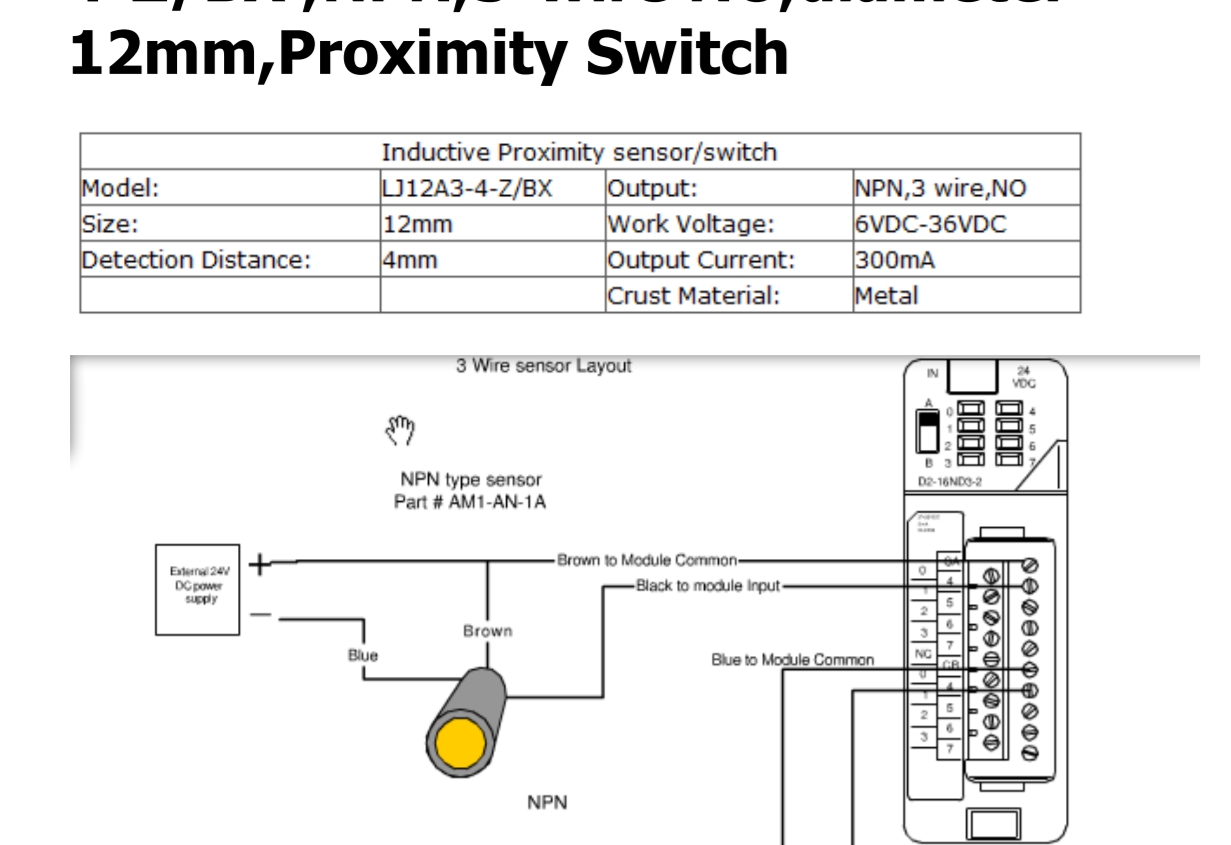
I am installing a 4mm inductive sensor to my Prusa I3. OMKON LJ12A3.4.Z/BX NPN as shown here
I have wired 12V directly from my power supply to a small PCB and from there to the brown(+) and blue(-) supply voltage.
When I lower the z axis the red LED on the sensor indicates that my aluminium heatbed has been detected.
I added 2 resistors 22k and 33k and wired and soldered then as voltage splitter.
In the meantime I had my Marlin updated just as described by Thomas Sanladerer in his video https://www.youtube.com/watch?v=EcGFLwj0pnA
UPDATE: The Sanlander video does not show a working solution! Most people had problems with the voltage splitter shown there. better forget it. read the comments underneath like:
Hi. I am using an LJ12A3-4-Z/BX.(NPN, NO). I powered it from 12 Volts. Tried both the resistor voltage divider and the regulator and they both work.
However, the high value isn't exactly 5 Volts, and the LED on the sensor is always on, a little darker when the sensor is not triggered. (That has no functionality effect, I just don't like it)
The reason why that happens is because the sensor's output is actually open collector, and the only thing sourcing 12 Volts to the output when the sensor is not triggered is the led circuit, which also has a 10k resistor.
A better solution to interface the sensor to the board is to use just a diode, like this:
- brown wire to 12 Volts,
- blue wire to Gnd
- black wire to the cathode of the diode
- anode of the diode to the processor input
- internal pull-up enabled!
Any diode would work, I used a 1N4148.
Now the processor 'sees' 5Volts for high and ~0.6Volts for Low (diode forward drop), which is perfectly safe.
And the LED turns on only when the sensor is triggered!
Schematic:
BROWN ---------- 12V
BLACK -----|<--- uP
BLUE ----------------GND
So as the LED goes on I measure 4.13V at the output. Connecting the black wire (sensor signal) to the RAMPS input the voltage is dragged down to almost 0V but I get no "triggered" readings when using M119 at Repetier.
So I replugged my old mechanic endstop to the RAMPS and did some testing. The mechanical endstop supplied a signal level of 4.88V and was recognized by the Repetier software. Once the signal is hooked to the RAMPS the voltage level there also goes down to almost 0V. So far no big difference.
If I use the sensor it puts 4.13V out, connected to the RAMPS it wont be recognized by Repetier as triggered only as OPEN.
Now before I spend nights of "research" any body on this forum who could point me into the right direction? Why is it so, that the sensor wont be able to trigger the event ?
And how come that though I changed all the settings (pullup etc.) according to the video above my old mechanic endstop still works?
Is 4.13V too low? I read anything above 0.6V should work for the Arduino. Did my voltage splitter setup reduce the needed current too much? (didnt have 10ks around so I used them instead of 10k vs 15k Ohms)
Any help is highly appreciated!
Edited 2 time(s). Last edit at 04/18/2017 09:13AM by maboo.
Blogs:
Meine 3D Druck Abenteuer
[3dptb.blogspot.de]
FLSUN Delta Drucker für Deutschland
[flsun-deutschland.blogspot.com]
Books on 3D patents:
[goo.gl] (english)
[www.amazon.de] (deutsch)
|
Re: Inductive sensor output does not trigger RAMPS April 16, 2017 01:14PM |
Registered: 8 years ago Posts: 5,232 |
|
Re: Inductive sensor output does not trigger RAMPS April 16, 2017 02:36PM |
Registered: 10 years ago Posts: 219 |
Reading through the datasheet again, it says that the LED should be ON permanently and go OFF when activated. In my case it is just the other way around 
And for the wiring: I did not connect the signal wire to common + because the RAMPS/Arduinio does not supply 12V but only 5V. I wired as described in the video.
Update: This voltage splitter shown below is not working for many sensors, read the whole thread!
instead of:
So if I connect them that could fry my Arduino. Or am I wrong here?
@O_Lampe: I tried that, but no chance even after a reset. I was a bit afraid to apply full 12V to the signal input, hope that did not break anything.
WARNING: Reading trough some internetsources in the Adafruitforum I found this:
Absolute max for I/O pins is 0.5+VCC. So if your VCC is 5V then the absolute max is 5.5V as an input. However, you shouldn't rely on the "absolutes" because those often mean some damage is occurring.
6-8V is definitely in the area of causing failures.
http://forum.arduino.cc/index.php?topic=194707.0
So the usage of a voltage devider is a must if you are using 12V (or more than 5V in general) as supply voltage!
Anything else as suggestion?
Edited 6 time(s). Last edit at 04/18/2017 09:15AM by maboo.
Blogs:
Meine 3D Druck Abenteuer
[3dptb.blogspot.de]
FLSUN Delta Drucker für Deutschland
[flsun-deutschland.blogspot.com]
Books on 3D patents:
[goo.gl] (english)
[www.amazon.de] (deutsch)
And for the wiring: I did not connect the signal wire to common + because the RAMPS/Arduinio does not supply 12V but only 5V. I wired as described in the video.
Update: This voltage splitter shown below is not working for many sensors, read the whole thread!

instead of:

So if I connect them that could fry my Arduino. Or am I wrong here?
@O_Lampe: I tried that, but no chance even after a reset. I was a bit afraid to apply full 12V to the signal input, hope that did not break anything.
WARNING: Reading trough some internetsources in the Adafruitforum I found this:
Absolute max for I/O pins is 0.5+VCC. So if your VCC is 5V then the absolute max is 5.5V as an input. However, you shouldn't rely on the "absolutes" because those often mean some damage is occurring.
6-8V is definitely in the area of causing failures.
http://forum.arduino.cc/index.php?topic=194707.0
So the usage of a voltage devider is a must if you are using 12V (or more than 5V in general) as supply voltage!
Anything else as suggestion?
Edited 6 time(s). Last edit at 04/18/2017 09:15AM by maboo.
Blogs:
Meine 3D Druck Abenteuer
[3dptb.blogspot.de]
FLSUN Delta Drucker für Deutschland
[flsun-deutschland.blogspot.com]
Books on 3D patents:
[goo.gl] (english)
[www.amazon.de] (deutsch)
|
Re: Inductive sensor output does not trigger RAMPS April 16, 2017 06:16PM |
Registered: 7 years ago Posts: 759 |
With a NPN NO probe, it has its own 10k ohm pullup resistor, so when un-trigered it will output its supply voltage (12v)
see here [i.stack.imgur.com]
The best way i found to connect a npn probe is just with a diode (cathode to probes black wire, anode to ramps signal pin).
The diode will block the 12v from reaching the ramps when prbe is not triggered, when the probe is triggered, its npn transistor will pull the endstop signal pin to 0v via the diode.
*note, controller endstop pullup resistor has to be enabled.
|
Re: Inductive sensor output does not trigger RAMPS April 17, 2017 12:20PM |
Registered: 8 years ago Posts: 5,232 |
|
Re: Inductive sensor output does not trigger RAMPS April 17, 2017 03:26PM |
Registered: 10 years ago Posts: 219 |
@Lampe: Thanks, I tried that again today and wired the sensor directly to RAMPS, hence using the 5V supply. The LED triggers correctly, but the input signal seems to be too weak to trigger the Arduino input port. The Repetier status was always Open or Triggered depending on the settings in Marlin, but never changed although the LED went off an on. Also I got a superlong hysteresis, the LED starts to glow about 10mm away from my aluminum board and then fully triggers when about 3mm away ;-(. So 5V Vcc is too low to be precise. It was only around 4.8V anyway, but the sensor Vcc is rated for 6V-36V.
Yes it MAY work sometimes, maybe because it is an analog circuit and reading trough the forum I learned that there is very little standartisation and anything is possible.
But I found a Arduino 5V relay in my Arduino box and I will try that out tonight, using 12V as Vcc and then trigger the relay as if it was an ordninary microswitch endstop.. Will report back.
Edited 1 time(s). Last edit at 04/17/2017 03:27PM by maboo.
Blogs:
Meine 3D Druck Abenteuer
[3dptb.blogspot.de]
FLSUN Delta Drucker für Deutschland
[flsun-deutschland.blogspot.com]
Books on 3D patents:
[goo.gl] (english)
[www.amazon.de] (deutsch)
|
Re: Inductive sensor output does not trigger RAMPS April 18, 2017 04:09AM |
Registered: 8 years ago Posts: 5,232 |
|
Re: Inductive sensor output does not trigger RAMPS June 15, 2017 06:27PM |
Registered: 6 years ago Posts: 262 |
I have a question regarding this subject if you don't mind me posting on someone else s thread 
I am researching what inductive sensor to order to compliment my soon to be built Ramps 1.4 setup.
I will be modifying the Ramps board for 24v electrics but that of coerce wont change the sensor pins that are just handed over to the Mega board at 5v
So many choices, whats the easiest and most reasonable setup? NPN/PNP NC/NO use a diode or use a voltage split resistor setup etc etc I am on a bit of information overload trying to put all the info into a coherent answer
I will be using this on an MK3 type board with a .8mm PEI layer on it. I have selected inductive over capacitive as I live in a coastal rain forest and humidity is a very likely issue.
I don't like the idea of a touch sensor at all....
oh and what size? M8 M12 M18? I don't want to use an oversized sensor and add unneeded mass to the head setup. Can I get away with a 2mm 5v M8 size sensor? With only .8mm of PEI between the sensor and the aluminum maybe but it feels a little short?
Thanx in advance
P.S. Right now from what I think I understand this seems to be the best bet for a plug in and go sensor.:
[www.aliexpress.com]
Edited 2 time(s). Last edit at 06/15/2017 06:40PM by JustSumGuy.
|
Re: Inductive sensor output does not trigger RAMPS June 18, 2017 11:07AM |
Registered: 7 years ago Posts: 759 |
Personally i would go with a NPN NO sensor as it can be connected to the endstop pin via a simple reverse biased diode( anode to endstop pin, cathode to probe) with endstop pullup resistor enabled, no need for a voltage divider network.
Go for a 8mm or 12mm sensing probe to reduce inacuracies due to probe heating up by being too close to the heated bed.
Go for a 8mm or 12mm sensing probe to reduce inacuracies due to probe heating up by being too close to the heated bed.
Sorry, only registered users may post in this forum.