24V with Ramps 1.4 questions
Posted by AVRkire
|
Re: 24V with Ramps 1.4 questions February 10, 2014 04:15PM |
Registered: 14 years ago Posts: 1,092 |
kscharf: That doesn't mean you shouldn't put a fuse on the output of the AC transformer (as well as the input!). Fuses are necessary regardless if it's AC or DC. You get a short somewhere without a fuse, and you get issues.
Also: You'd want to be very sure you're using bang-bang control of that SSR if you're switching the mains. You do NOT want to try switching 50 Hz AC on/off using an SSR in PWM mode, as you'll get a VERY nasty waveform. Run that into a transformer and you will not be guaranteed of getting out the right voltage (peak or RMS), as it'll fluctuate all over the place. You'd also want the waveform to zero cross (extra circuitry or an expensive zero-crossing SSR), so that you don't end up switching off at the top of the positive peak and on at the top of the negative peak.
If you did that on mains 240VAC, you'd send the voltage instantly swinging from ~+340V to -~340V. Apart from the current draw, the instant voltage swing induced on the secondary would be wildly inaccurate.
Part of the reason for using enclosed DC supplies is so that we don't have to TOUCH AC at all. They're easy to use, and they can be replaced by battery-backed supplies (eg: Solar batteries through a rectifier) in developing countries. And 24V is common enough in farm vehicles, which means that all sorts of other things can run on the same supply.
|
Re: 24V with Ramps 1.4 questions February 14, 2014 03:58AM |
Registered: 10 years ago Posts: 18 |
I was planning to try out a laptop "high power" supply, which is givin out 20v / 170w. As the power is still that low, the setup is without heated bed.
But. Then there is always the question how to feed the arduino ? I'm not willing to put the 20v thru D1 to arduino, but why couldnt i just solder out the D1 and replace it with a reversed Zener diode that has a zener voltage about 7- 12 v ? Sound like a plan to me, but am i missing something ?
In general, what is the purpose if the D1 ? It prevents the current flow from arduino to ramps direction, so if we use the zener setup, are we in trouble when we connect the the arduino to computer thru usb or is there broblems only when trying to power the arduino thru power jack ?
|
Re: 24V with Ramps 1.4 questions February 14, 2014 07:05AM |
Registered: 14 years ago Posts: 1,092 |
D1 stops the Arduino feeding power back to the12V line when powered from USB. If anything got switched on (eg: hot end), the current draw could kill the Arduino's onboard regulator. It also provides a tiny bit of reverse voltage protection if you connect the 12V input the wrong way.
Using a Zener will break this, as it will be forward biased and pass current when powered by USB. The other problem is that Zener diodes have very low current capabilities, so it would be unlikely to handle the current draw of the Arduino and the other +5V components on the RAMPS board (+5V side of the motor drivers, LCD/SD cards, etc).
You would be better removing D1, and running wires to a circuit to drop the voltage. Using a regulator (eg: 7809) to drop the voltage that would normally pass through D1 (the +12V side) down to something more acceptable. You STILL want D1 on the output of the regulator though, as the regulator will pass voltage from output to input (ie: It would fail in the same way as the zener).
Alternatively, you could just remove D1, and power the Arduino via USB. This could be a USB cable to the PC, or a USB smart phone charger.
|
Re: 24V with Ramps 1.4 questions March 24, 2014 03:31PM |
Registered: 10 years ago Posts: 8 |
I am converting some old lab equipment into a 3D printer and am using a 24v system. I have done all recommended on here but wonder if I run a 12v nozzle off of D8 (heat bed) and put the 11A input to a 12v source would work? I was going to add a step down converter from 24-12 and then wire to the 11A input.
I guess my question is will this work? Also I am a aero engineer not a coder or electrical guy so bear with me, what lines of code will I need to modify to make this work?
Edited 1 time(s). Last edit at 03/24/2014 03:33PM by behnt.
I guess my question is will this work? Also I am a aero engineer not a coder or electrical guy so bear with me, what lines of code will I need to modify to make this work?
Edited 1 time(s). Last edit at 03/24/2014 03:33PM by behnt.
|
Re: 24V with Ramps 1.4 questions March 24, 2014 05:48PM |
Registered: 10 years ago Posts: 14 |
|
Re: 24V with Ramps 1.4 questions March 24, 2014 08:18PM |
Registered: 14 years ago Posts: 1,092 |
behnt: Should work, but you won't have a headed bed output (that needs more current than the 5A input can provide, plus the FET will not be well cooled), unless you switch it through something like a SSR.
mkelly: if the heater is 1.1 ohm, at 24V that's closer to 22A, and possibly more at startup/cold. Note also that SSR's need to be mounted on a heatsink to handle their full current capacity. Also make sure you're using BANG-BANG control in your firmware, as the high switching speed of PID control on a heated bed will just make an SSR heat up faster.
mkelly: if the heater is 1.1 ohm, at 24V that's closer to 22A, and possibly more at startup/cold. Note also that SSR's need to be mounted on a heatsink to handle their full current capacity. Also make sure you're using BANG-BANG control in your firmware, as the high switching speed of PID control on a heated bed will just make an SSR heat up faster.
|
Re: 24V with Ramps 1.4 questions March 25, 2014 12:11PM |
Registered: 10 years ago Posts: 14 |
I had the SSR mounted to a heatsink. I got a replacement shipped to me and I'll be adding a cooling fan to the heatsink to hopefully prevent the SSR from overheating.Quote
Cefiar
mkelly: if the heater is 1.1 ohm, at 24V that's closer to 22A, and possibly more at startup/cold. Note also that SSR's need to be mounted on a heatsink to handle their full current capacity. Also make sure you're using BANG-BANG control in your firmware, as the high switching speed of PID control on a heated bed will just make an SSR heat up faster.
I'll re-verify but I'm almost positive the control is set to bang-bang.
If I blow this new relay with a heatsinked fan I think I'm going to go for a 40A relay like this one: [www.automationdirect.com] Not sure fi there's a cheaper 30-40A dc relay out there somewhere
|
Re: 24V with Ramps 1.4 questions April 02, 2014 07:44AM |
Registered: 10 years ago Posts: 32 |
Hi,
My solution for this:
[forums.reprap.org]
Google Translation:
RAMPS 1.4/24V
24V has several advantages:
- Much less voltage drop across cable / connector, since about 50% of the current only flows as at 12V
- And therefore less stress on the components (especially the MOSFET), thus less cooling is required and external relay for the Heatbed not be required
- More power at Heatbed, up to 20% possible
What is changed at the RAMPS:
- Replace the PTC fuses SMD fuses with holder (8A + 6.3A), thus better protection of the components during short circuits
- Install a step-down converter 24V> 12V (1A), on the one hand the Arduino 2560 and simultaneously fed 12V (screw) provides for other components (eg fans).
- Remove the diode D1
With this simple and cheap solution EVERY Arduino is 2560 24V compatible.
And the best, the charge on the 12V variant is only CHF 12 - (€ 9.70).
www.fredee.ch
Fredee
www.fredee.ch
info@fredee.ch
|
Re: 24V with Ramps 1.4 questions October 16, 2014 03:06PM |
Registered: 10 years ago Posts: 66 |
You'd need a fuse in there someplace! I simply meant that you don't need to double the voltage on the whole system, just on the heat bed. And you're right you are going to be limited to bang-bang control since an AC switching SS relay probably won't work well with PID (unless the software monitored the AC line and only switched on the correct portion of the wave form).
|
Re: 24V with Ramps 1.4 questions October 18, 2014 02:59AM |
Registered: 9 years ago Posts: 590 |
|
Re: 24V with Ramps 1.4 questions October 18, 2014 09:27PM |
Registered: 14 years ago Posts: 1,092 |
As has been mentioned elsewhere, use a correctly rated DC SSR with DC 24V.
The AC SSR's usually have basic zero-crossing circuitry in them, which means they only switch on/off when they go from positive to negative or vice versa (where they cross zero volts). If you use one on DC, it will never switch off and will probably fail to switch on except at startup, since the voltage never passes through zero volts.
The AC SSR's usually have basic zero-crossing circuitry in them, which means they only switch on/off when they go from positive to negative or vice versa (where they cross zero volts). If you use one on DC, it will never switch off and will probably fail to switch on except at startup, since the voltage never passes through zero volts.
|
Re: 24V with Ramps 1.4 questions January 16, 2015 12:50PM |
Registered: 9 years ago Posts: 752 |
Just wanted to share my experience on 12V heated beds on 24V.
I've got the following setup:
- Prusa i3 printer
- 12V 5A PSU for RAMPS 1.4 and arduino
- 24V 15A for heated bed cheap chinese PSU
- RAMPS board is a clone that supports 24V (fuse2 rated at 30V, 9A, markings: 30 FU900)
- MOSFETS on the board are IRF3205, Vds = 55V, Rdson = 8mOhm, Id = 110A. This MOSFET is a lot better than the original specced board. Vds is higher and the Rdson about a third of the original, which means that it will get far less hot. There are many MOSFETS that are suitable. Just lookup the datasheet of the MOSFET on your board and look for these values. IRLB8743 is also a good alternative.
- MK2b heated bed, 12V. Resistance = 1.26 Ohm. This means I = U/R 12/1.26 = 9.5A@12V, 24/1.26 = 19A@24V
I've made no changes to the RAMPS 1.4 board. I've been running the 12V MK2b for a couple of hours with no problems so far. The 24V PSU can only provide 15A so you need to bring the average current draw down. This is very easy to do in Marlin firmware by setting the #define in configuration.h:
#define MAX_BED_POWER
You'll need to know the current draw at 24V of the heatedbed. The best way is to use a milliohm meter. Most digital multimeters don't have the accuracy in the 0-10 ohm range. I've build one myself and output the ohmage is 10mv per milliohms. See: Milliohm DIY
Once you've got the resistance, it's easy to calculate the current draw. Formula:
U = I x R (U is voltage, I is current, R is resistance)
I = U / R (isolate I)
I = 24/1.26 (my MK2b has 1.26 ohm resistance, replace it with your measurement)
I = 19A (this is in my case and used as an example, please calculate your own value as this is critical for correctly setting the current draw as to not overload the fuse or powersupply).
It is recommended to have a power supply that has about 25-50% or more current to spare or it will run very hot and doesn't last too long.
The fuse on my RAMPS board can take 9A. I've been printing a 9.5 without any problems so I'll keep that as a guide. The PCB tracks are rated at 11A so we need to be careful not to cross this threshold at the very least. If you want to put in a higher current you'll need to use a solid state relais.
At 24V my board draws 19A current which is double than the fuse can take. 19/2 = 9.5A. That's the value we need on average and is about 2/3 of the powersupply which can output 15A.
To get at the multiplication factor for your power supply use this formula:
duty cycle factor = fuse maximum current / Heated bed current draw at 24V
example:
duty cycle factor = 9.5 / 19 = 0.5
The MAX_BED_POWER defines the maximum duty cycle at any given time, be it if you're using PID, BANG-BANG or BANG-BANG with hysteresis. The value can be between 0 and 255. So 50% duticycle is half of 255, that's 127.
Formula:
MAX_BED_POWER = 255 x duty cycle factor
example:
MAX_BED_POWER = 255 x 0.5 = 127 (rounded)
You enter this in the configure.h without the equal sign:
#define MAX_BED_POWER 127
Recompile and upload and your RAMPS/arduino (or any other board) board is ready. When the heated bed led is blinking instead of a steady light you'll know that it has worked. If it's still steadily lighting up something is wrong, turn off immediately.
So you might think why lowering the current through the heated bed by using PWM if you've got more available? Here are a few points:
- The 12V rated heated bed is rated at a given current, the PCB tracks will heat up within the tolerances of the PCB. Higher current might push it beyond the tolerances and start to burn. It's better to increase the voltage than to increase the current.
- The total power output is increased with 24V compared to 12V. ie P = U x I, with 12V that's 12 x 9.5 = 114W. With 24V it's 24 x 9.5 = 228W. Double of 12V wattage.
- 19A is a lot of current, especially if your PSU is rated lower than what the heatbed draws. But it can handle it if the average currentdraw is lower. Using PWM by setting MAX_BED_POWER lower than 255 it will on average use a lower current. It still draws the full 19A for a very short period, then 0A for the rest of the duration. With a setting of 127 and normal current draw at 19A the average is then 9.5A. This switching happens about 7.6 times per second and the 24V 15A PSU that I use seems to handle it without any problem.
I use two separate power supplies as the heatbed draws a lot of power and will give a dip in the voltage. This might have an effect on the stepper motors and fans. Whenever the heated bed is heating, the fan cooling the hotend heatbreak slows down, a sure sign that the voltage drops.
Hope this helps someone!
|
Re: 24V with Ramps 1.4 questions January 20, 2015 01:28AM |
Registered: 9 years ago Posts: 6 |
hai friends, im new to 3d printing and im having doubts in connectin input voltage.
generaly ramps 1.4 needs, 12-35vdc as input voltages and 11amps, 5amps are need to connect to run ramps1.4 circuit.
my question is what will happen if i connect 24vdc(voltage) and 15A(amps) to the input of ramps1.4....
thank you......smiling smiley
generaly ramps 1.4 needs, 12-35vdc as input voltages and 11amps, 5amps are need to connect to run ramps1.4 circuit.
my question is what will happen if i connect 24vdc(voltage) and 15A(amps) to the input of ramps1.4....
thank you......smiling smiley
|
Re: 24V with Ramps 1.4 questions January 20, 2015 04:32AM |
Registered: 10 years ago Posts: 14,672 |
Please don't cross post. I have already answered this in the Developers forum.
Large delta printer [miscsolutions.wordpress.com], E3D tool changer, Robotdigg SCARA printer, Crane Quad and Ormerod
Disclosure: I design Duet electronics and work on RepRapFirmware, [duet3d.com].
Large delta printer [miscsolutions.wordpress.com], E3D tool changer, Robotdigg SCARA printer, Crane Quad and Ormerod
Disclosure: I design Duet electronics and work on RepRapFirmware, [duet3d.com].
|
Re: 24V with Ramps 1.4 questions May 18, 2015 02:46AM |
Registered: 11 years ago Posts: 25 |
Curious how did you handle the wiring ? Schematic?
I have a 12 setup across the board. with a 12 to 24 v stepup converter for my heated bed.
I want to leave everything as is. except for the HEated bed so I thought I would add a standalon 24V PS . Id lose the 12 to 24 step up converter in lou of the new 24v ps.
But how to tie it in? I know on the out put side... it just goes to the heater. but How does the Arduino/ramps turn it off and on?
TIA
S
SamR
MendelMax... (A build for ever in process... ... ... will it/ Is it ever done!?) yea, Its done alright its sitting collecting dust!
Moved onto a Creality CR-10
I have a 12 setup across the board. with a 12 to 24 v stepup converter for my heated bed.
I want to leave everything as is. except for the HEated bed so I thought I would add a standalon 24V PS . Id lose the 12 to 24 step up converter in lou of the new 24v ps.
But how to tie it in? I know on the out put side... it just goes to the heater. but How does the Arduino/ramps turn it off and on?
TIA
S
Quote
imqqmi
Just wanted to share my experience on 12V heated beds on 24V.
I've got the following setup:
- Prusa i3 printer
- 12V 5A PSU for RAMPS 1.4 and arduino
- 24V 15A for heated bed cheap chinese PSU
- RAMPS board is a clone that supports 24V (fuse2 rated at 30V, 9A, markings: 30 FU900)
- MOSFETS on the board are IRF3205, Vds = 55V, Rdson = 8mOhm, Id = 110A. This MOSFET is a lot better than the original specced board. Vds is higher and the Rdson about a third of the original, which means that it will get far less hot. There are many MOSFETS that are suitable. Just lookup the datasheet of the MOSFET on your board and look for these values. IRLB8743 is also a good alternative.
- MK2b heated bed, 12V. Resistance = 1.26 Ohm. This means I = U/R 12/1.26 = 9.5A@12V, 24/1.26 = 19A@24V
I use two separate power supplies as the heatbed draws a lot of power and will give a dip in the voltage. This might have an effect on the stepper motors and fans. Whenever the heated bed is heating, the fan cooling the hotend heatbreak slows down, a sure sign that the voltage drops.
Hope this helps someone!
SamR
MendelMax... (A build for ever in process... ... ... will it/ Is it ever done!?) yea, Its done alright its sitting collecting dust!
Moved onto a Creality CR-10
|
Re: 24V with Ramps 1.4 questions May 19, 2015 01:43AM |
Registered: 9 years ago Posts: 752 |
If you look at the ramps board below, the power block on the lower left has 4 terminals to hook up the psu. The lower two wires are for the hotend and motors, 5A current max, the upper two is a separate supply line just for the heated bed at 11A max. You can hook up the 24 V dedicated psu on this.
In the firmware you need to enable the heated bed and set the corresponding ntc or thermo couple type. Make sure the heated bed supports 24V.
If it's setup correctly, the host software like pronterface and repetier host should recognise the heated bed, and allow you to set the temperature. Make sure the temperature that's indicated without heating is about right at room temperature. One of the mosfets on the board is controlled by the arduino and will do the switching, bang-bang or using PID. See the wiki on reprap for the schematic of the ramps board.
[docs.my-home-fab.de]
Cheers
Imqqmi
|
Re: 24V with Ramps 1.4 questions May 19, 2015 01:50AM |
Registered: 11 years ago Posts: 25 |
Imqqmi,
So I can leave the 5A input connector with the current 12PSU.
and in addition use the 11a input connector a 24vPSU.?
if this is correct. then remove my 12v to 24v Heated bed stepup voltage device and just wire straight to my heated bed?
(just to reitterate I currently have a heated bed. its a 24v model but uses a 12V to 24v step up converter)
-Sam
FWiW the image you provided shows only 1 PSU. mine is currenty wired like the one in the image but solely 12v.
Edited 1 time(s). Last edit at 05/19/2015 01:50AM by TheSniper.
SamR
MendelMax... (A build for ever in process... ... ... will it/ Is it ever done!?) yea, Its done alright its sitting collecting dust!
Moved onto a Creality CR-10
|
Re: 24V with Ramps 1.4 questions May 19, 2015 02:56AM |
Registered: 9 years ago Posts: 752 |
Yes, replace the step up converter by your dedicated 24V psu, that should do the trick. To avoid confusion, you say straight to the heated bed, which would mean without wiring it to the ramps board, that's not correct. You just need to wire the 24V to the 11A connector and the heated bed to it's own connector as is described in the wiki, to connector D8.
|
Re: 24V with Ramps 1.4 questions May 19, 2015 03:07AM |
Registered: 9 years ago Posts: 1,159 |
Quote
imqqmi
Yes, replace the step up converter by your dedicated 24V psu, that should do the trick. To avoid confusion, you say straight to the heated bed, which would mean without wiring it to the ramps board, that's not correct. You just need to wire the 24V to the 11A connector and the heated bed to it's own connector as is described in the wiki, to connector D8.
And don't forget to replace the polyfuse it is only rated to 16V. use a Car type blade fuse/holder in its place.
|
Re: 24V with Ramps 1.4 questions May 19, 2015 03:16AM |
Registered: 11 years ago Posts: 25 |
All,
Good info, Ill see if I can give it all some time today/tomorrow! BTW what about the diode that powers the arduino? I can leave all that alone right?
Also what size fuse should I replace with?
SamR
MendelMax... (A build for ever in process... ... ... will it/ Is it ever done!?) yea, Its done alright its sitting collecting dust!
Moved onto a Creality CR-10
|
Re: 24V with Ramps 1.4 questions August 21, 2015 03:20PM |
Registered: 11 years ago Posts: 72 |
I have the same trouble with my large sized heated bed.
I am out of my PLA filament, so preparing everything for ABS plastic filament for the first time.
My heated bed will not cross 75C as it is larger MK1 version.
I have considered clubbing 2 ATX PSU boxes to make a 24V PSU.
Then it occurred to me that I can add a 12v PSU in parallel to the D8 output (with a diode) to heat up the bed faster.
RAMPS controls the D8 output in RAMPS, to regulate the temperature, while the second PSU supplies the extra current.
Is there any flaw in this idea?
|
Re: 24V with Ramps 1.4 questions August 21, 2015 04:28PM |
Registered: 9 years ago Posts: 752 |
Switching psu's don't take putting in series very well, and in parallel with a diode isn't going to work as the voltage drop over the diode will interfere with getting the power into the heated bed. You need a 19 to 24V psu 15 amps or more, set up the firmware so that it puts 11 amps average max. Iirc i set mine at 192 duty cycle (192 from 256 is 75%). If you fail to do so the 12V heated bed will draw a larger current and trip the fuse. You could of course bypass the on board mosfet using an external mosfet or solidstate relais. But you risk ovetloading the pcb, but i guestimate you could reach 110 degrees within 3 minutes.
|
Re: 24V with Ramps 1.4 questions August 22, 2015 12:47AM |
Registered: 14 years ago Posts: 1,092 |
Peddipath: If your PSU isn't up to the task of running the heated bed AND all the rest, then you can use TWO PSU's with RAMPS as you've got 2 power inputs.
Connect your smaller PSU to the 5A input. This runs the motors and the hot end.
Connect your larger PSU to the 11A input. This runs just the heated bed.
This assumes that the PSU is losing volts when your RAMPS board tries to run everything. If not, it's not likely to help.
FWIW: There are 3 places you mainly drop voltage, causing your bed not to heat well:
1. PTC fuses. They can drop a bit of voltage near their max current. You are better off replacing them with fuses. The one that supplies the motors should be about 5-7.5A max, and the one that does the heated bed should be no more than 15A, as the board simply won't work well at anything higher. You may also find that replacing the D8 FET with a better class of FET than the original will help .
2. FET's. The original STP55N06L's are pretty poor compared to something like an IRLB3813. You will lose less volts and also it will heat up less if you replace them.
3. Wiring. Wiring designed for higher currents will have less resistance per meter. This means that less of your precious volts gets dropped on the wiring. This includes wires from your PSU to your RAMPS board, and from your RAMPS board to your heated bed. I personally use the silicon coated ultra-flexible stuff that is used predominantly in RC racing, as it's designed to carry lots of current, have very low resistance, and is very flexible. If it's going near a heated bed tho, I'd cover the ends with heatshrink, just in case.
|
Re: 24V with Ramps 1.4 questions September 12, 2015 03:42AM |
Registered: 9 years ago Posts: 245 |
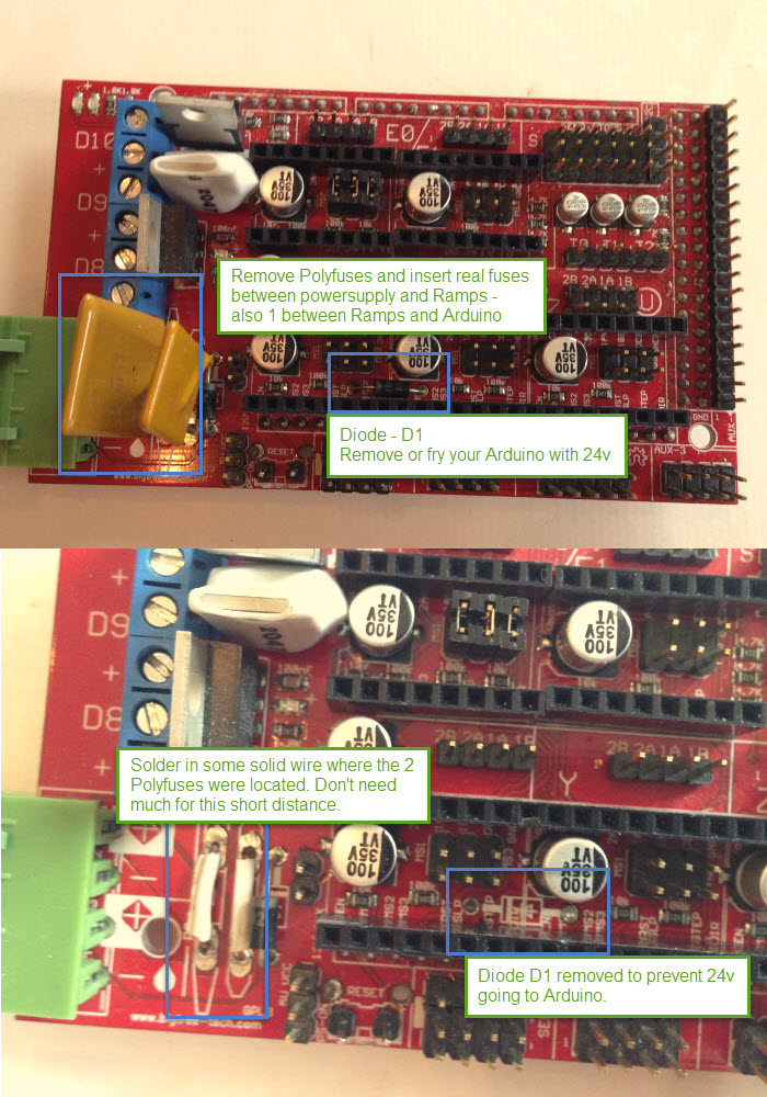
Wanted to show my before and after photos of getting my Ramps to run on 24v. (see attached modify-to-24v.jpg)
I spent a lot of time as I'm not electronical or electrical person, and I honestly just don't understand it when people toss around a lot of technical terms and link to datasheets.
I need to know what to look for specifically and not how to calculate something based on findings I need to find in schematics.
Check out the "Make-sure-caps-are-35v.jpg" image to see what to check for.
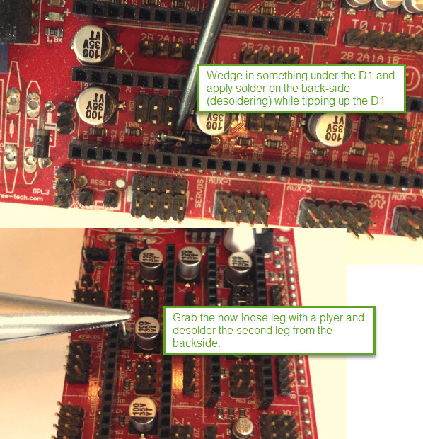
How I removed D1 - see attached desolder.jpg:
1) Wedged a thin-metal-something under the D1 and the female-plugs where the drivers goes.
2) Turned Ramps over. Solder extra solder-lead on the D1 legs (back-side of Ramps) while using the metal-wedge to tip out the D1.
3) Grab the D1 with a plier and do the same de-soldering on the second leg.
4) Melt the lead and suck it up with a lead-sucker.
How to remove the Polyfuses:
1) Use a plier or something and grab 1 leg of the Polyfuses.
2) Turn Ramps over. Solder extra solder-lead on the polyfus leg (back side) you have grabbed and pull it out, while applying extra solder-lead.
3) Do the same for all 4 Polyfuse legs.
4) Melt the lead and suck it up with a lead sucker.
Provide power to Arduino now:
Find a 12v or 5v powersource and provide power to Arduino through the Bullet-plug.
12v works on one of mine just fine, but on the other, the Arduino can't provide 5v through Ramps Aux pins, so had to give it 5v.
Edited 3 time(s). Last edit at 09/12/2015 03:49AM by dintid.
I spent a lot of time as I'm not electronical or electrical person, and I honestly just don't understand it when people toss around a lot of technical terms and link to datasheets.
I need to know what to look for specifically and not how to calculate something based on findings I need to find in schematics.
Check out the "Make-sure-caps-are-35v.jpg" image to see what to check for.
How I removed D1 - see attached desolder.jpg:
1) Wedged a thin-metal-something under the D1 and the female-plugs where the drivers goes.
2) Turned Ramps over. Solder extra solder-lead on the D1 legs (back-side of Ramps) while using the metal-wedge to tip out the D1.
3) Grab the D1 with a plier and do the same de-soldering on the second leg.
4) Melt the lead and suck it up with a lead-sucker.
How to remove the Polyfuses:
1) Use a plier or something and grab 1 leg of the Polyfuses.
2) Turn Ramps over. Solder extra solder-lead on the polyfus leg (back side) you have grabbed and pull it out, while applying extra solder-lead.
3) Do the same for all 4 Polyfuse legs.
4) Melt the lead and suck it up with a lead sucker.
Provide power to Arduino now:
Find a 12v or 5v powersource and provide power to Arduino through the Bullet-plug.
12v works on one of mine just fine, but on the other, the Arduino can't provide 5v through Ramps Aux pins, so had to give it 5v.
Edited 3 time(s). Last edit at 09/12/2015 03:49AM by dintid.
|
Re: 24V with Ramps 1.4 questions April 02, 2016 09:58AM |
Registered: 8 years ago Posts: 21 |
Sorry for reviving such an old thread, but based on the info here and elsewhere, going to 24v sounds like a hassle. A small boost of 1-2 volts seems like enough for me, but before I commit to buying a variable-output PSU, is there any problem with sending 14 volts through the standard 12v RAMPS setup with absolutely no changes to the printer? Everything in the printer (to my knowledge) is 12v. I figure I've already fried two arduinos, might as well do the smart thing and ask before I do any of this.
Alternatively, since this thread says that one of the RAMPS inputs is for bed power only, could I use this to step down voltage from a 24v psu to 12v for the arduino, hotend, and steppers, and then run direct 24v from the PSU to the bed through the RAMPS board?
Edited 1 time(s). Last edit at 04/02/2016 10:24AM by kenblu24.
|
Re: 24V with Ramps 1.4 questions April 02, 2016 03:17PM |
Registered: 9 years ago Posts: 752 |
You can get a 24v psu and power only the heated bed with it. Check the 11A polyfuse and make sure the maximum current should be limited using the maximum pwm setting if you use a 12V only heated bed. This has worked for me for about a year without any problems.
--
Kind regards
Imqqmi
NFAN CoreXY printer:
[reprap.org]
--
Kind regards
Imqqmi
NFAN CoreXY printer:
[reprap.org]
|
Re: 24V with Ramps 1.4 questions May 25, 2016 09:01AM |
Registered: 8 years ago Posts: 18 |
Hi,
I know I'm 3 years late with this question but I'd be grateful if you could elaborate a bit on this part of your answer
I know I'm 3 years late with this question but I'd be grateful if you could elaborate a bit on this part of your answer
I do have 2 power supplies and I'm thinking of using the 24V one for the heatedbed. As far as I can understand I should connect the 24V PS to the 11A input of the ramps and the 12V PS to the 5A. What I don't understand is how to tie them together on the RAMPS board on the ground pin.Quote
Cefiar
You can run the 11A input on 24V and the 5A on 12V if you have either two power supplies or one that produces both voltages. If you are using two power supplies, they will be tied together via the RAMPS board on the ground pin. In 99.9% of cases this should be fine, as long as the PSU have independent grounds (some cheap knock-offs do not). You can also do the reverse if you remove the diode D1, assuming other components are rated appropriately.
|
Re: 24V with Ramps 1.4 questions May 25, 2016 01:05PM |
Registered: 9 years ago Posts: 752 |
If you connect both power supplies, effectively you tie both the 12V psu ground to 24V psu ground through the PCB tracks on the RAMPS. Some cheap and badly designed psu units may not have a properly decoupled ground and will cause a short circuit. It may be prudent to use a resistor between the two grounds without connecting it to anything else and see if it heats up. If one is not decoupled, it poses a danger to yourself too, so take proper precautions of not touching the wires.Quote
Khaled
I do have 2 power supplies and I'm thinking of using the 24V one for the heatedbed. As far as I can understand I should connect the 24V PS to the 11A input of the ramps and the 12V PS to the 5A. What I don't understand is how to tie them together on the RAMPS board on the ground pin.
--
Kind regards
Imqqmi
NFAN CoreXY printer:
[reprap.org]
|
Re: 24V with Ramps 1.4 questions May 26, 2016 02:29AM |
Registered: 9 years ago Posts: 245 |
I just Draw a line directly from DC GND out on one PSU and DC GND out on the other PSU. Always worked on every cheap chinese PSU I've ever used.Quote
Khaled
Hi,
I know I'm 3 years late with this question but I'd be grateful if you could elaborate a bit on this part of your answer
I do have 2 power supplies and I'm thinking of using the 24V one for the heatedbed. As far as I can understand I should connect the 24V PS to the 11A input of the ramps and the 12V PS to the 5A. What I don't understand is how to tie them together on the RAMPS board on the ground pin.Quote
Cefiar
You can run the 11A input on 24V and the 5A on 12V if you have either two power supplies or one that produces both voltages. If you are using two power supplies, they will be tied together via the RAMPS board on the ground pin. In 99.9% of cases this should be fine, as long as the PSU have independent grounds (some cheap knock-offs do not). You can also do the reverse if you remove the diode D1, assuming other components are rated appropriately.
I live in the EU though. The US have some strange wiring compared to the rest of the World, so if you are in the US it might be different.
Edited 1 time(s). Last edit at 05/26/2016 02:29AM by dintid.
My Instructables - both total newbie instructables and some for intermediate users.
My Designs on Thingiverse
YouTube channel containing a few 3D printing videos - they are videos for my Instructables, and mostly not standalone.
Ultius / Tantillus Thingiverse Group
|
Re: 24V with Ramps 1.4 questions July 16, 2017 07:56AM |
Registered: 9 years ago Posts: 6 |
Hello imqqmi. You seem to know what you are talking about. Please chime in on this situation:
Regarding ONLY stepper motors and the configured Vref for them: i use 12V psu, 1.5A stepper, and VRef is 0.75V - as indicated in the SD8825 drivers manual "The SD8825 uses a 0.10 ohm current sense resistor so current limit can be computed as follows: Current Limit = VREF x 2".
So, i'm "using" the science behind the thing and not that "more or less" approach you read often to configure the VRef.
I then changed to a 24V psu, and VRef now reads 0,375V (half of the previous value).
Question: do i need to readjust VRef? Is yes, by how much?
Thank you so much in advance. o/


Sorry, only registered users may post in this forum.