Makerbot Endstops / Wiring Kit / RAMPS 1.4 mismatch
Posted by Karmavore
|
Re: Makerbot Endstops / Wiring Kit / RAMPS 1.4 mismatch January 28, 2014 08:36PM |
Registered: 12 years ago Posts: 1,236 |
@ken
I am still puzzled why you rejected your original sketch, as it was correct. The sketch does not mention pin 1, although your post did, and that is where the confusion seems to have crept in. Anyway, that is water under the bridge.
I would say forget about pin numbers, it is the pin function we are concerned with. "Pin 1" is a movable feast, so doesn't necessarily help to disambiguate.
The second sketch is I believe incorrect and is NOT SAFE to connect. Unfortunately it is now spreading around the forums and appears in Google searches. It would be really great if you could find away to remove it. You also have posts saying that the first sketch is incorrect, which is also misleading.
I appreciate your attempt to help, and the diagrams are beautifully drawn, but in this case it is leading to more confusion.
What is Open Source?
What is Open Source Hardware?
Open Source in a nutshell: the Four Freedoms
CC BY-NC is not an Open Source license
|
Re: Makerbot Endstops / Wiring Kit / RAMPS 1.4 mismatch January 29, 2014 12:38AM |
Registered: 10 years ago Posts: 10 |
A week or so ago, I published a sketch and posted it here, asking for answers.There are a lot of generic Reprap `Combination' packages on the market with little reference as to how things connect. Two days later, I posted another sketch as based on follow-up responses. Still looking for answers. The second sketch reversed the pin-outs as it appears that many generic endstop manufacturers used a `dot' to identify their perceived pin #1, and this was corroborated by a generic manufacturer's pin-out reference. This information is & was incorrect. It was the reverse (opposite) the pin-out numbering found on the open sourced original design, which was copied.
DO NOT use either sketches posted on 22 jan 14 or 24 jan 14 as reference.
There is a `lag time' between when something is posted, where it goes, how quickly people reference and respond. Some skim a post, or fail to catch a clarification/correction in later ones. There have been some folks who missed the mention the quest for answers and information. Same thing with the second sketch which was based on initial responses to the first. The intention was to document the means to connect generic Mechanical Endstops with RAMPS 1.4. Currently, I question if that can be accomplished in this specific combination.
DO NOT use either sketches posted on 22 jan 14 or 24 jan 14 as reference.
PLEASE READ bobc's earlier responses. His comments make sense of it all. I have since used a battery source, per advice. The best thing said was only use the Signal pin and the Gnd Pin on the generic Mechanical Endstop devices(s) - either endstop device #2 or #3 pin. Things will be fine & work. The battery test is smart & has little probabilty of damaging the endstop device. Things made sense with a Multimeter. The issue is the amount of electricity which flows between the Signal and the Vcc on endstops in my possession. Too much, too soon. No wonder there are boards burning out.I managed to get the LED to light, connecting the Vcc. However things got too hot too fast i.e. a lot of current was going through there. The weak link in the circuit is not on the RAMPS, it is on the Arduino Controller, which destructs quickly. Based on the recent post, it is prudent to ignore connecting the Vcc pins on either the RAMPS or endstop device.
Today, I tried calling MakerBot to visit with someone in Engineering & Design, in hopes of hearing what they were thinking and the basis of the Vers 1.2 Mech Endstop. http://www.thingiverse.com/thing:4971 After phone shuffling, it was suggested I send an e-mail request to their PR Department. My thinking was that their endstop device was designed for the controller they used. Their devices may handle certain loads, which a RAMPS/MEGA combination may not be capable of sustaining.
Please use the information contained in the Sketch dated 27Jan14. It:
- incorporates the most current comments to date
- ignores connecting Vcc ( on some RAMPS 1.4 identified as "+" ) and Vcc on generic Mechanical Endstop devices. Do we really need a LED telling you it is doing something?
- identifies the simple option of using a part of the device, the Switch, as originally identified in the RAMPS 1.4 wiki
A lot of people are referencing this Forum. Based on recent comments, I am posting what is hopefully the LAST Sketch. The intention was to identify a way of using generic Mechanical Endstops with a RAMPS 1.4 board. Looking at the participation and comments on this Forum, much of that has occurred. This sketch is posted in hopes people will reference this, and the previous ones shall be ignored.
This SUPERSEDES Sketches posted on 24 Jan 14 and 22 Jan 14.
DO NOT USE THOSE SKETCHES AS REFERENCES
Thanks to bobc, jmaeding, Cefair, CanCakes, vreighen for their help and comments.
ken
DO NOT use either sketches posted on 22 jan 14 or 24 jan 14 as reference.
There is a `lag time' between when something is posted, where it goes, how quickly people reference and respond. Some skim a post, or fail to catch a clarification/correction in later ones. There have been some folks who missed the mention the quest for answers and information. Same thing with the second sketch which was based on initial responses to the first. The intention was to document the means to connect generic Mechanical Endstops with RAMPS 1.4. Currently, I question if that can be accomplished in this specific combination.
DO NOT use either sketches posted on 22 jan 14 or 24 jan 14 as reference.
PLEASE READ bobc's earlier responses. His comments make sense of it all. I have since used a battery source, per advice. The best thing said was only use the Signal pin and the Gnd Pin on the generic Mechanical Endstop devices(s) - either endstop device #2 or #3 pin. Things will be fine & work. The battery test is smart & has little probabilty of damaging the endstop device. Things made sense with a Multimeter. The issue is the amount of electricity which flows between the Signal and the Vcc on endstops in my possession. Too much, too soon. No wonder there are boards burning out.I managed to get the LED to light, connecting the Vcc. However things got too hot too fast i.e. a lot of current was going through there. The weak link in the circuit is not on the RAMPS, it is on the Arduino Controller, which destructs quickly. Based on the recent post, it is prudent to ignore connecting the Vcc pins on either the RAMPS or endstop device.
Today, I tried calling MakerBot to visit with someone in Engineering & Design, in hopes of hearing what they were thinking and the basis of the Vers 1.2 Mech Endstop. http://www.thingiverse.com/thing:4971 After phone shuffling, it was suggested I send an e-mail request to their PR Department. My thinking was that their endstop device was designed for the controller they used. Their devices may handle certain loads, which a RAMPS/MEGA combination may not be capable of sustaining.
Please use the information contained in the Sketch dated 27Jan14. It:
- incorporates the most current comments to date
- ignores connecting Vcc ( on some RAMPS 1.4 identified as "+" ) and Vcc on generic Mechanical Endstop devices. Do we really need a LED telling you it is doing something?
- identifies the simple option of using a part of the device, the Switch, as originally identified in the RAMPS 1.4 wiki
A lot of people are referencing this Forum. Based on recent comments, I am posting what is hopefully the LAST Sketch. The intention was to identify a way of using generic Mechanical Endstops with a RAMPS 1.4 board. Looking at the participation and comments on this Forum, much of that has occurred. This sketch is posted in hopes people will reference this, and the previous ones shall be ignored.

This SUPERSEDES Sketches posted on 24 Jan 14 and 22 Jan 14.
DO NOT USE THOSE SKETCHES AS REFERENCES
Thanks to bobc, jmaeding, Cefair, CanCakes, vreighen for their help and comments.
ken
|
Re: Makerbot Endstops / Wiring Kit / RAMPS 1.4 mismatch January 29, 2014 12:47AM |
Registered: 10 years ago Posts: 10 |
Bob -
Thank you for your comments. More importantly, your help and explanation.
I shall contact the forum co-ordinator and see if the second sketch can be pulled. It needs to disappear.
If you think we could provide a better reference & guide, let me know. I would love to have a `clean, clear' illustration for reference.
Sincerely
ken
|
Re: Makerbot Endstops / Wiring Kit / RAMPS 1.4 mismatch January 29, 2014 11:57AM |
Registered: 10 years ago Posts: 87 |
|
Re: Makerbot Endstops / Wiring Kit / RAMPS 1.4 mismatch February 03, 2014 04:58AM |
Registered: 10 years ago Posts: 83 |


|
Re: Makerbot Endstops / Wiring Kit / RAMPS 1.4 mismatch February 03, 2014 11:38AM |
Registered: 10 years ago Posts: 10 |
Tino-
I am disappointed to learn about your issue.
Had you had followed this forum, you would discover that the 24 Jan 14 illustration posted the 24th. has been removed.
That posted illustration was based on the generic manufacturer's references posted on the web.
THAT INFORMATION IS AND WAS INCORRECT.
The 24 Jan 14 illustration removed.
There are any number of later posts to this forum following up, identifying issues.
I tried to correct the misinformation with an illustration posted 28 Jan 14. This illustration works.
Hopefully, replacing an affordable RAMPS board is easily remedied, and everything else goes well.
Cheers,
ken
|
Re: Makerbot Endstops / Wiring Kit / RAMPS 1.4 mismatch February 03, 2014 12:27PM |
Registered: 10 years ago Posts: 87 |
AquaPro,
Surely you do not come to discussion forums expecting every post to be an answer.
The nature of forums is trial and error, and drawings (even wrong ones) help that process, not hurt it.
Ken's communication has been clear, not ultimate answers every time, which is all we could ask.
Actually, I did ask for more sketches, or a book of them if Ken is willing
I encourage you to do the same, say "this seemed to work, but can anyone comment"....if you are unsure.
The posts about not connecting anything to the VCC pin of RAMPS 1.4 boards are the results of the discussions as I understood them.
Edited 1 time(s). Last edit at 02/03/2014 12:28PM by jmaeding.
|
Re: Makerbot Endstops / Wiring Kit / RAMPS 1.4 mismatch February 04, 2014 04:09AM |
Registered: 10 years ago Posts: 83 |
|
Re: Makerbot Endstops / Wiring Kit / RAMPS 1.4 mismatch February 04, 2014 11:49AM |
Registered: 10 years ago Posts: 87 |
Aquapro,
Hang in there, but realize I did not misunderstand your thought, which I compliment you on being able to express through another language.
I stand by the idea that people should post whatever they want, and state their experience the best they can.
It sounds like both of us are at the same stage, starting up the electronics. I wish you luck and do the same for me
|
Re: Makerbot Endstops / Wiring Kit / RAMPS 1.4 mismatch February 04, 2014 12:52PM |
Registered: 10 years ago Posts: 10 |
I am sorry you got caught up in this. I have asked the moderator to remove that attached illustration, and possibly the post.
If I go back, and review all the posts in this forum, there are great points and suggestions. There are also great questions. There are obscure, less obvious answers - bobc pointed out that many devices, which find their way to the market, are often fabricated through direct copy, by people whose primary language is that of commerce, and not the somewhat common english. Often there are misunderstandings in identification. A dot (possibly ) indicating a pin number could be one. Or rearranging pin designation labels in different numeric order. I found a seller's website with this problem which created the confusion and the incorrect sketch. Their device was a perfect copy of the original design. Their screened ( printed ) references contradicted the original, as did their reference sheet pin-outs.
In private correspondence with karmavore, he mentioned that it is our responsibility to research, test, research, test, then act. There is an inherent risk in what we connect. jmaeding makes similar comments. Good thoughts. This is one of those rarely mentioned pieces in the forum. Much like Edison, everyone is figuring out over a thousand ways, how not to make a 3D printer... but somewhere out there, the journey becomes the better experience than the destination
Please use the last illustration as a guide. If, and only if you feel brave, test the VCC pins on the Mechanical Endstop boards. You might possibly connect them to your RAMPS. Remember, when I tested mine, using Bobc's suggestion, a couple of AAA batteries, they heated up too fast, implying there was little, if any resistance.on the devices I got in the mail. That could further damage your components, most likely the Mega controller board.
Possibly there is a philosophical `Rule' here.
If a component within a set of connected components fails, It shall be the most expensive component which fails first.
Let me know how things work out on your printer. I tend to think everyone involved with this forum, yourself included, hopes for the best, to see a lot of success in bringing our fabrications to life.
Thanks for your comments...
Cheers!
ken
If I go back, and review all the posts in this forum, there are great points and suggestions. There are also great questions. There are obscure, less obvious answers - bobc pointed out that many devices, which find their way to the market, are often fabricated through direct copy, by people whose primary language is that of commerce, and not the somewhat common english. Often there are misunderstandings in identification. A dot (possibly ) indicating a pin number could be one. Or rearranging pin designation labels in different numeric order. I found a seller's website with this problem which created the confusion and the incorrect sketch. Their device was a perfect copy of the original design. Their screened ( printed ) references contradicted the original, as did their reference sheet pin-outs.
In private correspondence with karmavore, he mentioned that it is our responsibility to research, test, research, test, then act. There is an inherent risk in what we connect. jmaeding makes similar comments. Good thoughts. This is one of those rarely mentioned pieces in the forum. Much like Edison, everyone is figuring out over a thousand ways, how not to make a 3D printer... but somewhere out there, the journey becomes the better experience than the destination
Please use the last illustration as a guide. If, and only if you feel brave, test the VCC pins on the Mechanical Endstop boards. You might possibly connect them to your RAMPS. Remember, when I tested mine, using Bobc's suggestion, a couple of AAA batteries, they heated up too fast, implying there was little, if any resistance.on the devices I got in the mail. That could further damage your components, most likely the Mega controller board.
Possibly there is a philosophical `Rule' here.
Let me know how things work out on your printer. I tend to think everyone involved with this forum, yourself included, hopes for the best, to see a lot of success in bringing our fabrications to life.
Thanks for your comments...
Cheers!
ken
|
Re: Makerbot Endstops / Wiring Kit / RAMPS 1.4 mismatch February 04, 2014 05:24PM |
Registered: 14 years ago Posts: 1,092 |
|
Re: Makerbot Endstops / Wiring Kit / RAMPS 1.4 mismatch February 04, 2014 07:35PM |
Registered: 10 years ago Posts: 87 |
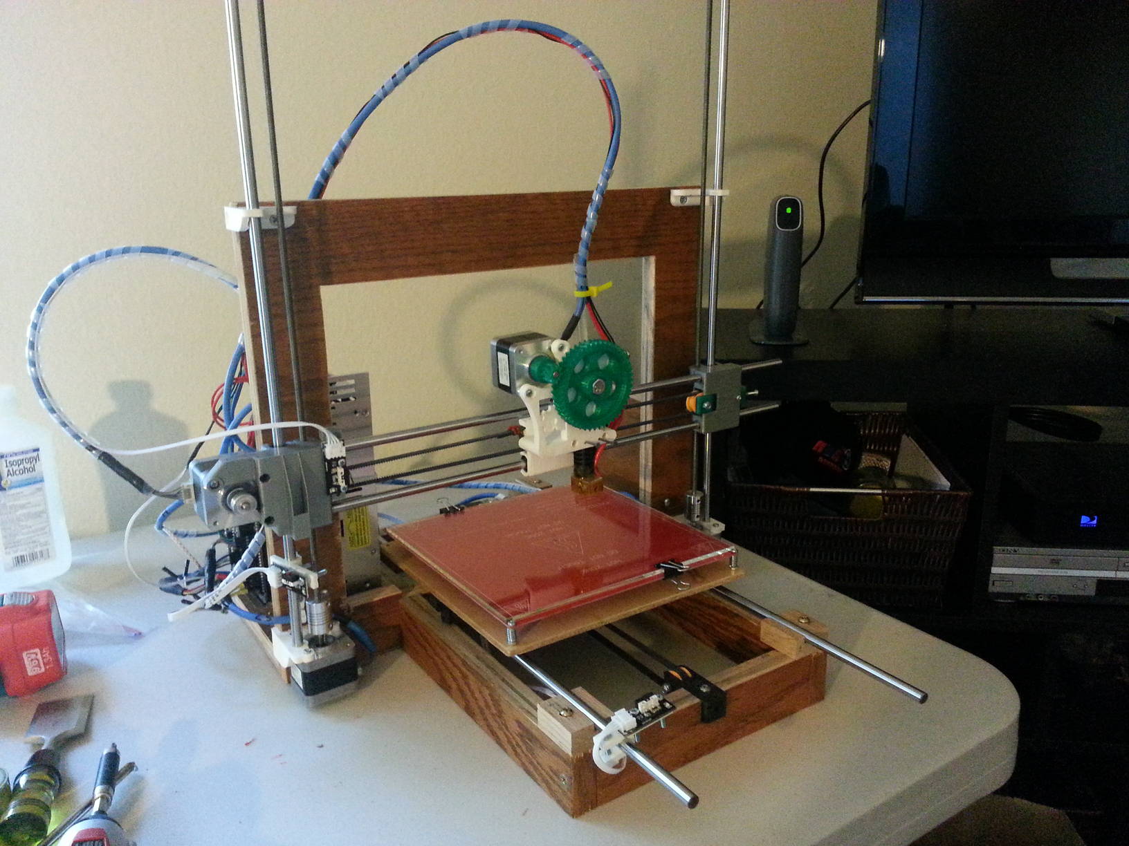
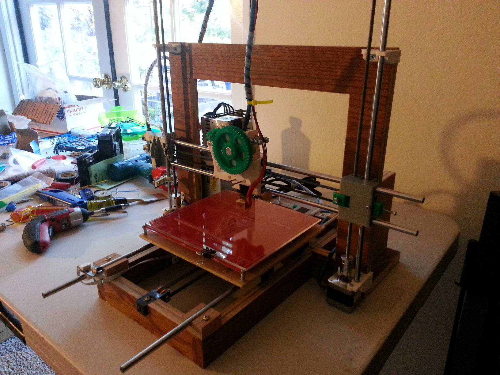
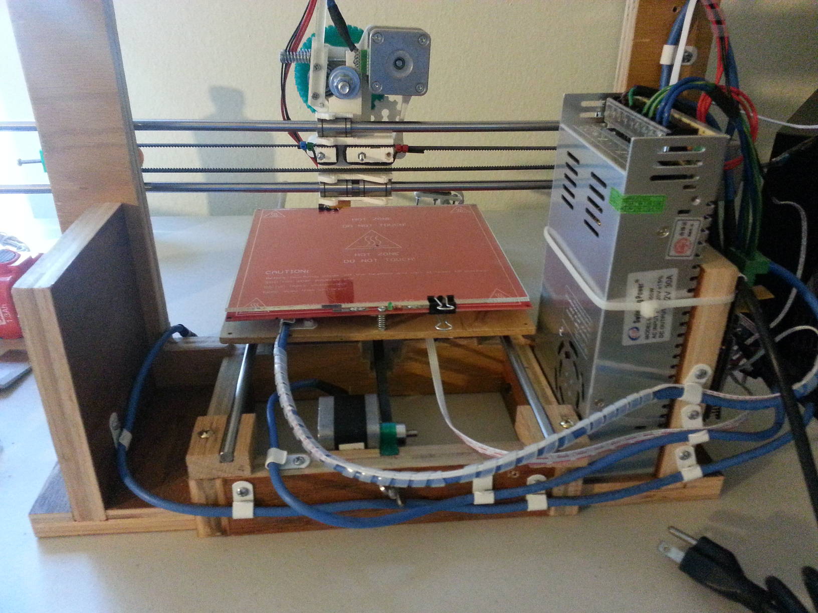
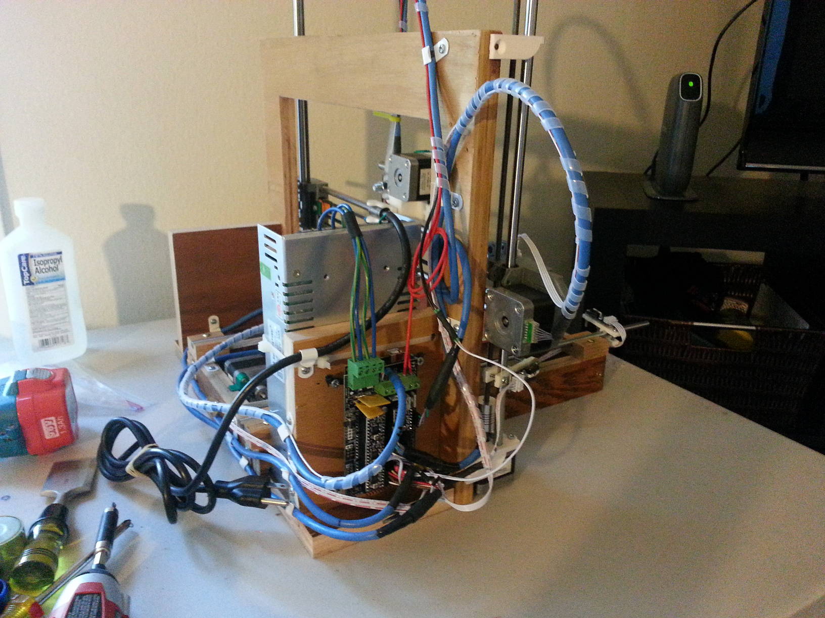
BTW, a few pics of the Prusa I3 I put together.
I did a wood frame instead of threaded rod, as I have lots of wood and tools to cut it.
The "wings" that connect vert frame to y axis also give a place for power supply.
Hope it does not burn down when I start it up. Time will tell.
I did a wood frame instead of threaded rod, as I have lots of wood and tools to cut it.
The "wings" that connect vert frame to y axis also give a place for power supply.
Hope it does not burn down when I start it up. Time will tell.
|
Re: Makerbot Endstops / Wiring Kit / RAMPS 1.4 mismatch February 04, 2014 07:49PM |
Registered: 10 years ago Posts: 10 |
|
Re: Makerbot Endstops / Wiring Kit / RAMPS 1.4 mismatch February 12, 2014 01:16PM |
Registered: 10 years ago Posts: 87 |
An update - the switches are working fine with the two wires, signal and ground.
Be sure your configuration.h file has:
#define ENDSTOP_PULLUP_X_MIN true
#define ENDSTOP_PULLUP_Y_MIN true
#define ENDSTOP_PULLUP_Z_MIN true
#define ENDSTOP_PULLUP_X_MAX true
#define ENDSTOP_PULLUP_Y_MAX true
#define ENDSTOP_PULLUP_Z_MAX true
for any endstops, I only use 3 for min limits, the max items here do nothing if no switches.
For those wishing me luck on my startup, it went ok, but my RAMPS board x axis is messed up, it causes the driver and motor to heat up fast.
It behaves otherwise. I tested on other motors, drivers, cables, and its not them. I killed a driver this way.
So I switched x axis pins in pins.h to spare extruder 2, and moved the (new) driver and stepper cable to extruder 2.
EXCEPT, the driver got plugged in one pin off.
Power on, smoke rising....
New mega on its way from Amazon Prime, 2 days.
The funny thing is the mega behaves ok without ramps power on. I can upload firmware fine.
As soon as ramps power supply is plugged in, the mega is unrecognized by windows.
I nuked the power handler on the mega it seems, it did not like the shock therapy.
I didn't like it either, glad I don't have one of those integrated mega/ramps boards.
|
Re: Makerbot Endstops / Wiring Kit / RAMPS 1.4 mismatch May 03, 2014 12:24PM |
Registered: 9 years ago Posts: 7 |
I have just connected my Sainsmart mechanical endstops to my Megatronics v2.0 according to this diagram
[forums.reprap.org]
They light up when pressed and my megatronics is smoke free. Looks like this wiring works for sainsmart endstops/megatronics setup
[forums.reprap.org]
They light up when pressed and my megatronics is smoke free. Looks like this wiring works for sainsmart endstops/megatronics setup
|
Re: Makerbot Endstops / Wiring Kit / RAMPS 1.4 mismatch June 14, 2014 07:55PM |
Registered: 9 years ago Posts: 4 |
Here's my understanding of the connections that work for me without smoke!!!

|
Re: Makerbot Endstops / Wiring Kit / RAMPS 1.4 mismatch July 02, 2014 11:53AM |
Registered: 9 years ago Posts: 1 |
|
Re: Makerbot Endstops / Wiring Kit / RAMPS 1.4 mismatch July 02, 2014 12:38PM |
Registered: 10 years ago Posts: 10 |
hgstel -
My first drawing, in this thread, with three wires, works.
Early in this thread, Bobc's comments are good things to read. His comments describe differences between manufacturers, the how's & why's of some of the confusion. He talks about testing. These are all good things. If you have doubts, reading his comments a few times, then test. I found that a lower voltage battery works well.
Our friend jmaeding's configurations for your config file should be referenced.
My second drawing is taken from early Ramps 1.4 schematics and works, though things may be confusing on the config end.
The fellow from nathionaleventphotography's images work.
Hope all this makes sense, that things work out and there is no blue smoke
ken
|
Re: Makerbot Endstops / Wiring Kit / RAMPS 1.4 mismatch April 22, 2015 08:59PM |
Registered: 10 years ago Posts: 8 |
|
Re: Makerbot Endstops / Wiring Kit / RAMPS 1.4 mismatch April 22, 2015 09:56PM |
Registered: 9 years ago Posts: 977 |
|
Re: Makerbot Endstops / Wiring Kit / RAMPS 1.4 mismatch April 23, 2015 01:06AM |
Registered: 10 years ago Posts: 8 |
|
Re: Makerbot Endstops / Wiring Kit / RAMPS 1.4 mismatch April 23, 2015 12:05PM |
Registered: 10 years ago Posts: 87 |
|
Re: Makerbot Endstops / Wiring Kit / RAMPS 1.4 mismatch April 26, 2015 07:47PM |
Registered: 10 years ago Posts: 8 |
|
Re: Makerbot Endstops / Wiring Kit / RAMPS 1.4 mismatch April 26, 2015 11:11PM |
Registered: 10 years ago Posts: 87 |
no, the endstops still would be hooked to the ramps, and the config file settings apply.
The thing to be careful about is whatt wires go to what pins. I recall that the only thing you can mess up if no circuit board, is the normally closed or open, which is easy to reverse in the config file.
Be careful here, and look at the wiki for "normal" setup without a board. email me at jmaeding123 you know the symbol hunsaker dot com (remove the 123) if you want help.
thx
Edited 1 time(s). Last edit at 04/26/2015 11:13PM by jmaeding.
|
Re: Makerbot Endstops / Wiring Kit / RAMPS 1.4 mismatch May 02, 2015 08:13AM |
Registered: 9 years ago Posts: 245 |
I'm having issues figuring endstops out as well. I have yet to connect them as I'm afraid to ruin something.
I'm using Ramps 1.4 with marlin on it.
I have the Mechanical Endstops v1.2 as shown on all the images in this thread.
I have the wiring figured out and learned the Vcc might Work, or not, depending on quality.
How to test endstop using Multimeter? I do not know what to look for.
What I do not know for sure is the firmware settings:
I do offcourse need make sure endstops are enabled, then:
I do the following as the endstops have pullups on board, so disabling the RAMPS onboard pullup resistors.
// #define ENDSTOPPULLUPS
I don't know if I need to set this to true or false, and what the consequences could be?
// Mechanical endstop with COM to ground and NC to Signal uses "false" here (most common setup).
const bool X_MIN_ENDSTOP_INVERTING = false;
const bool Y_MIN_ENDSTOP_INVERTING = false;
const bool Z_MIN_ENDSTOP_INVERTING = false;
const bool X_MAX_ENDSTOP_INVERTING = false;
const bool Y_MAX_ENDSTOP_INVERTING = false
const bool Z_MAX_ENDSTOP_INVERTING = false;
I have 6 endstops, so planning on using all 6 like so:
#define DISABLE_MAX_ENDSTOPS
#define DISABLE_MIN_ENDSTOPS
Edited 1 time(s). Last edit at 05/02/2015 08:14AM by dintid.
|
Re: Makerbot Endstops / Wiring Kit / RAMPS 1.4 mismatch August 08, 2017 01:46PM |
Registered: 6 years ago Posts: 4 |
|
Re: Makerbot Endstops / Wiring Kit / RAMPS 1.4 mismatch October 04, 2018 05:22PM |
Registered: 5 years ago Posts: 1 |
My biggest problem is:
How to make these Mechanical Endstop V1.2 normaly connected?
with:
X_MIN_ENDSTOP_INVERTING = false its permanently triggered i see it with m119
X_MIN_ENDSTOP_INVERTING = True is working perfectly after I disconnected the wire and it was working . so its in normaly open mode
using an ampmeter with black on COM and red on NC it gives connected signal and stops when microswitch closes at the same time led lights which is a normal behaviour for NC
Any ideas how to make this switch NC instead of NO?
Im on the verge of sacrificing one endstop and start cuting things
Edited 1 time(s). Last edit at 10/04/2018 05:23PM by MauDaFaca.
|
Re: Makerbot Endstops / Wiring Kit / RAMPS 1.4 mismatch October 04, 2018 06:04PM |
Registered: 10 years ago Posts: 87 |

Sorry, only registered users may post in this forum.