Home
>
Developers
>
Topic
Just another 330x330x300 Ultimaker with direct drive dual extrusion
Posted by jerryjs8
|
Just another 330x330x300 Ultimaker with direct drive dual extrusion August 03, 2017 07:22AM |
Registered: 6 years ago Posts: 50 |
Hello RepRap, glad to be a part of the community! Read a lot from these forums over the years and hope to contribute back in the same spirit that drives this movement.
But first, an introduction! My name is Joseph, and I am 3D printing infected... So much that I decided to try and make a go at my own design.
Hopefully some of you will contribute to the discussion about my build, and hopefully when it's finalized the community will take from it and make a better one! So without further adieu, here it is.
-------------------------------------------------------------------
I started modelling the new printer from scratch back in December 2016 to overcome some of the weaknesses in my current eBay CTC Bizer (at first it was a long list, but it's gotten shorter as I've continued modifying the CTC).
Current picture of the CTC with a mess of modifications. The print bed and the extruder are my own design. I plan on getting the extruder online sometime, but the print bed is already on [www.thingiverse.com].
The CTC prints fine, but it's not big enough!
Now I'm just building a printer that can print in sizes I need for some projects I've been brewing up.
Main objectives for the build:
1. Enjoy constructing and building the project
2. Utilize my dual direct drive extruder (originally made for the CTC)
3. Simple and robust construction for accurate and repeatable prints
4. Big print volume without a gigantic frame
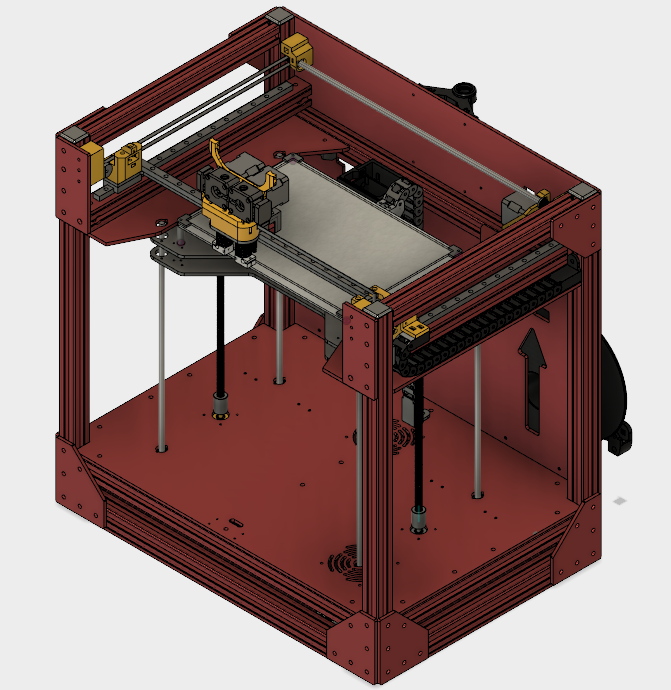
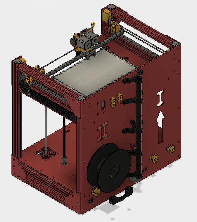
Rendered photos:
The frame is 516x514x535mm and houses a printing volume of 330x330x300mm. Kinda just looks like an Ultimaker imported into a Replicator 1 frame, but there's no need to overcomplicate things just so it looks different.
The XY gantry is the typical Ultimaker style but with 10mm Igus linear aluminium rods and bushings. Some will instantly cry out `deflection!` for using aluminium rods, but the unsupported length where the extruder is riding on is "only" 400mm. On my CTC Bizer I have two 8mm aluminum rods that are just a shy shorter than 400mm unsuported, and I haven't seen any loss in quality due to deflection or a sagging cradle since switching out the steel rods. That and going aluminium saves 1.16 kg of weight. But if it doesn't work out, I can always put in steel.
0.9° nema 17 motors with 16 teeth gears drive the larger 32 teeth gears on the rotating assembly. For both X and Y axes there are min and max limit switches for the runout. Since the design is very compact, there needs to be a safety in case of missed steps during a print; limit switches can activate a macro to cancel the print in case of emergency.
For the belts I absolutely wanted closed loop belts so I designed a tensioner system that gets rid of the Ultimaker tensioner block and spring design and also routes the belts around the front window panel (always bugged me how you can see the belts through the window on the Ultimakers).
The dual direct drive extruder was the biggest piece of the puzzle and the heart of the design. I think I spent three times as much time designing it as I did for the rest of the printer.
Taking two round 0.9° nema 14 motors I have designed an extruder that for this printer should weigh in at around 350 grams and is considerably smaller than mounting two E3D Titans. I plan to use DC42's IR probe as seen attached to the slider and the Duet3D ethernet version controller. This will give me the 32 bit controller (going to have a lot of steps per mm with 2:1 reductions and 0.9° motors) with a lot of fuctionalities that will make the printer both easy to use and a joy to use, not to mention have it run quieter than my CTC (video of that box screaming at 120mm/s [www.facebook.com]). In addition I can forgo mounting a display since it has the web interface.
The printing surface will be a 6mm cast aluminum plate with three-point leveling. Underneath it'll be insulated with fiberglass wool. The z-axis will be moved by three SFU1204 ballscrews and a 0.9° nema 23, also with 16 and 32 teeth pulleys. The reason I went with a nema 23 is so that I can run a lower current through the motor and get more than enough torque without having to worry about the temperature of the motor. Underneath the frame there won't be a whole lot of air moving, and since that's where the two 24v power supplies are mounted it'll probably be more warm than cool.
Because I wanted such a large printing volume, closed loop belts and a compact design, there are some places where I don't have much spare room. Although if I'm building a precision machine, I shouldn't be sweating 2mm of running clearance.
Last week I lasered out a prototype housing to do a test run and see if the belt tensioner system is going to work as intended.
Indeed it does!
-------------------------------------------------------------------
If you guys have any thoughts on weaknesses of the design, I'd appreciate your input.
One thing I'm still considering is if I need pillow blocks for supporting the rods on both sides of the pulleys. Something like this [www.thingiverse.com]
Otherwise stay tuned, soon I'm going to begin the real construction!!!!
-------------------------------------------------------------------
Once all the bugs are worked out I will release the the STL, STEP and DXF files to the public.
But in preparation for the future...
License
The Hulk 3D Printer is released under CERN OHL 1.2
Edited 12 time(s). Last edit at 08/03/2017 09:36AM by jerryjs8.
But first, an introduction! My name is Joseph, and I am 3D printing infected... So much that I decided to try and make a go at my own design.
Hopefully some of you will contribute to the discussion about my build, and hopefully when it's finalized the community will take from it and make a better one! So without further adieu, here it is.
-------------------------------------------------------------------
I started modelling the new printer from scratch back in December 2016 to overcome some of the weaknesses in my current eBay CTC Bizer (at first it was a long list, but it's gotten shorter as I've continued modifying the CTC).
Current picture of the CTC with a mess of modifications. The print bed and the extruder are my own design. I plan on getting the extruder online sometime, but the print bed is already on [www.thingiverse.com].

The CTC prints fine, but it's not big enough!

Now I'm just building a printer that can print in sizes I need for some projects I've been brewing up.
Main objectives for the build:
1. Enjoy constructing and building the project
2. Utilize my dual direct drive extruder (originally made for the CTC)
3. Simple and robust construction for accurate and repeatable prints
4. Big print volume without a gigantic frame
Rendered photos:
The frame is 516x514x535mm and houses a printing volume of 330x330x300mm. Kinda just looks like an Ultimaker imported into a Replicator 1 frame, but there's no need to overcomplicate things just so it looks different.


The XY gantry is the typical Ultimaker style but with 10mm Igus linear aluminium rods and bushings. Some will instantly cry out `deflection!` for using aluminium rods, but the unsupported length where the extruder is riding on is "only" 400mm. On my CTC Bizer I have two 8mm aluminum rods that are just a shy shorter than 400mm unsuported, and I haven't seen any loss in quality due to deflection or a sagging cradle since switching out the steel rods. That and going aluminium saves 1.16 kg of weight. But if it doesn't work out, I can always put in steel.
0.9° nema 17 motors with 16 teeth gears drive the larger 32 teeth gears on the rotating assembly. For both X and Y axes there are min and max limit switches for the runout. Since the design is very compact, there needs to be a safety in case of missed steps during a print; limit switches can activate a macro to cancel the print in case of emergency.

For the belts I absolutely wanted closed loop belts so I designed a tensioner system that gets rid of the Ultimaker tensioner block and spring design and also routes the belts around the front window panel (always bugged me how you can see the belts through the window on the Ultimakers).

The dual direct drive extruder was the biggest piece of the puzzle and the heart of the design. I think I spent three times as much time designing it as I did for the rest of the printer.

Taking two round 0.9° nema 14 motors I have designed an extruder that for this printer should weigh in at around 350 grams and is considerably smaller than mounting two E3D Titans. I plan to use DC42's IR probe as seen attached to the slider and the Duet3D ethernet version controller. This will give me the 32 bit controller (going to have a lot of steps per mm with 2:1 reductions and 0.9° motors) with a lot of fuctionalities that will make the printer both easy to use and a joy to use, not to mention have it run quieter than my CTC (video of that box screaming at 120mm/s [www.facebook.com]). In addition I can forgo mounting a display since it has the web interface.

The printing surface will be a 6mm cast aluminum plate with three-point leveling. Underneath it'll be insulated with fiberglass wool. The z-axis will be moved by three SFU1204 ballscrews and a 0.9° nema 23, also with 16 and 32 teeth pulleys. The reason I went with a nema 23 is so that I can run a lower current through the motor and get more than enough torque without having to worry about the temperature of the motor. Underneath the frame there won't be a whole lot of air moving, and since that's where the two 24v power supplies are mounted it'll probably be more warm than cool.

Because I wanted such a large printing volume, closed loop belts and a compact design, there are some places where I don't have much spare room. Although if I'm building a precision machine, I shouldn't be sweating 2mm of running clearance.


Last week I lasered out a prototype housing to do a test run and see if the belt tensioner system is going to work as intended.

Indeed it does!

-------------------------------------------------------------------
If you guys have any thoughts on weaknesses of the design, I'd appreciate your input.
One thing I'm still considering is if I need pillow blocks for supporting the rods on both sides of the pulleys. Something like this [www.thingiverse.com]
Otherwise stay tuned, soon I'm going to begin the real construction!!!!
-------------------------------------------------------------------
Once all the bugs are worked out I will release the the STL, STEP and DXF files to the public.
But in preparation for the future...
License
The Hulk 3D Printer is released under CERN OHL 1.2
Edited 12 time(s). Last edit at 08/03/2017 09:36AM by jerryjs8.
|
Re: Just another 330x330x300 Ultimaker with direct drive dual extrusion August 04, 2017 02:07AM |
Registered: 8 years ago Posts: 5,232 |
Pretty interesting design, especially the unguided z-axis!
I also have three 1204 leadscrews for Z, but the bed is also fixed by two linear rails. Maybe overkill?
Will be interesting to hear your findings.
I don't have hands on experience with plywood frames, but you seem to be pretty convident about building the box true and square?!
At least, I don't see many parts that allows adjustment/alignment corrections.
I'd go for self aligning bearings for the rods.
|
Re: Just another 330x330x300 Ultimaker with direct drive dual extrusion August 04, 2017 07:57AM |
Registered: 6 years ago Posts: 50 |
Thanks, finally getting it together is a lot of fun!
I may be overconfident in the straightness of the ballscrews, but the ones I have on the shelf look pretty well manufactured to not have any considerable wobble, therefore I thought additional rod guides would be overkill. Will see how that all works out, but at the back wall I have enough room to put some guides if it does end up being a problem later.
Do you have pictures of your design? I'd be interested to see how you built your z-axis.
And the wooden box is not the material I'm going to be using for the frame, that was just a test to see if the measurements for the closed loop belts were accurate. I guess I forgot to mention the real frame is going to be cut out of 6mm aluminium plates with a waterjet cutter. Therefore I can only hope the dimentional accuracy will let me get away with not needing adjustment/alignment of the gantry. But again, I could be wrong about that too. At that point I'll have to be creative, but there's always a solution! Perhaps even those self aligning bearings if I have to.
|
Re: Just another 330x330x300 Ultimaker with direct drive dual extrusion August 04, 2017 09:26AM |
Registered: 6 years ago Posts: 50 |
You got me thinking about the straightness of the 1204's, so I got them out and measured. Sure enough, krumm wie eine Banana! Not really, the worst I have is a wobble of 0.12mm and the other two are 0.05mm and 0.10mm. At the ends they're all very well machined and centered, so the wobble would be (very big generalization) at it's worst at 150mm z-height and then get better towards the max height of 300mm. I don't know if I'd be able to correct that with guiding rods, or if it would even be noticable on the print surface with 4mm pitch and a three rod system?
|
Re: Just another 330x330x300 Ultimaker with direct drive dual extrusion August 04, 2017 09:38AM |
Registered: 11 years ago Posts: 5,780 |
I think you're overly constraining yourself by requiring closed loop belts (except for the small ones that the motor uses to drive the larger pulleys). Belts always need some means of tensioning and you're setting yourself up for trouble if you don't design it in from the start. The small belts need to be tensioned, too, and in your design the easiest way would be to use slots to mount the motors so they can be moved to tension the belts.
Water jet cutters are not super precise. (see [wardjet.com]). The kerf is usually tapered- wider on the top of the cut piece and narrower on the bottom with the amount of taper depending upon the cutting speed. That means holes will be tapered, larger on the top and smaller on the bottom. If you're going to have the holes cut, I'd have them cut small and plan on opening them with a drill. I think it would be better to just drill the holes after the waterjet cutting is done because they can be accurately located that way, assuming you have access to tools to do so. You're relying on the accuracy of the hole positions to align the guide rails parallel to each other. What's your fallback plan if that doesn't work out?
I would not have much confidence in using unguided ball screws. I suggest you select and design in the exact guide rails you're going to install if the unguided screws fail to deliver the required lateral stability. That way, if the ball screws don't perform adequately, you can simply bolt in the guide(s) with minimal disassembly of the machine. The next question is if the ball screws aren't perfectly straight, with 3 of them pushing/pulling laterally on the bed support, how big do the guide rails have to be to prevent Z wobble in the prints? The design of the coupling to the ball nuts can help if they allow for some lateral motion of the screw without translating that into lateral motion of the bed support. Have you considered a belt lifted Z axis?
Putting electronics in the bottom of the machine is a great way to use some of the dead space, but if the Z axis isn't working and you need to get at the electronics, you have to get the bed up and out of the way by manually twisting one of the ball screws You might want to plan for that contingency and design a removable crank that can be fit over the end of one of the ball screws through the top of the printer. Otherwise, maybe a hinge that allows the bulk of the machine (including the Z axis) to tilt back while the base with the electronics remains flat on the table.
You're 90% of the way to having an enclosed printer that would allow printing ABS. All you need to add is panels to cover the holes, and to get the electronics out of the enclosed space. If you made the machine taller, you could put the electronics in the bottom, separated from the build volume by an insulating panel. You might need more height at the top of the mechanism, too to feed filament.
Edited 2 time(s). Last edit at 08/04/2017 10:38AM by the_digital_dentist.
Ultra MegaMax Dominator 3D printer: [drmrehorst.blogspot.com]
|
Re: Just another 330x330x300 Ultimaker with direct drive dual extrusion August 04, 2017 04:47PM |
Registered: 6 years ago Posts: 50 |
Quote
the_digital_dentist
I think you're overly constraining yourself by requiring closed loop belts (except for the small ones that the motor uses to drive the larger pulleys). Belts always need some means of tensioning and you're setting yourself up for trouble if you don't design it in from the start. The small belts need to be tensioned, too, and in your design the easiest way would be to use slots to mount the motors so they can be moved to tension the belts.
As far as the closed loop system, what I was testing with the wooden housing was the degree of movement I have in the tensioner to see if it would be enough. Here are two pictures illustrating the design
Tensioner at rest (slack)

Tensioner at full range (taut)

And the way the X and Y motors are mounted are already using slots to be able to adjust the belt tension, was just hard to see in the photos, so I cropped one to show the X motor slots in the back.

Here's a 360° video to better visualize the box
[youtu.be]
That's all stuff I should have posted in the initial introduction, but it's all the little details that get forgotten first...
Quote
the_digital_dentist
Water jet cutters are not super precise. (see [wardjet.com]). The kerf is usually tapered- wider on the top of the cut piece and narrower on the bottom with the amount of taper depending upon the cutting speed. That means holes will be tapered, larger on the top and smaller on the bottom. If you're going to have the holes cut, I'd have them cut small and plan on opening them with a drill. I think it would be better to just drill the holes after the waterjet cutting is done because they can be accurately located that way, assuming you have access to tools to do so. You're relying on the accuracy of the hole positions to align the guide rails parallel to each other. What's your fallback plan if that doesn't work out?
Very good point with the kerf, and also something I've been talking with the experts about.
 I work at a technical university in Germany and the guy who is going to cut out the frame doesn't have much concern about that with only a 6mm aluminium sheet. To get an idea of the expertise I have the pleasure in dealing with, here's an overview of his research [www.awt.uni-hannover.de] (in German, but lots of pictures) He's working on some really cool stuff like 3d waterjet abrasion, where he designed a 3 axis suspended abrasive waterjet that just wreaks havoc on ceramic in comparison to injector waterjets. I'd take some pictures when I go to the production hall, but most of the good stuff is already in the presentation slides.
Nevertheless, we already decided to do exactly what you suggested and are going to take a piece of test aluminium and see how accurate the holes are going to be. If necessary we'll just cut pilot holes and I'll machine them to spec. Since I'm still waiting on the plates, we haven't been able to get to the good stuff yet. Pictures will be posted!!!
Plan B? Ream out the holes to 22mm and mount the bearings using sliding adjustable caps mounted from the outside. Just hope it doesn't come to that!
Quote
the_digital_dentist
I would not have much confidence in using unguided ball screws. I suggest you select and design in the exact guide rails you're going to install if the unguided screws fail to deliver the required lateral stability. That way, if the ball screws don't perform adequately, you can simply bolt in the guide(s) with minimal disassembly of the machine. The next question is if the ball screws aren't perfectly straight, with 3 of them pushing/pulling laterally on the bed support, how big do the guide rails have to be to prevent Z wobble in the prints? The design of the coupling to the ball nuts can help if they allow for some lateral motion of the screw without translating that into lateral motion of the bed support. Have you considered a belt lifted Z axis?
Belt lifted z-axis, no. Thought about it, but everything about it just seems overcomplicated for what it is. Maybe I just overthought the construction, do you have any examples of what you mean?
As for adding guide rods for later on, that wouldn't be such a big deal. Just a quick thought and a draft, that doesn't involve rods along the back wall, I could reprint the top bearing spindle to have a flexible TPU core for the ballscrew bearing to walk around in and add a through rod on the same mount piercing the printbed plate for the lateral stability. Here's a quick illustration of what I mean.
Top view

Bottom view

Hopefully you get the idea. Maybe that'd be a sufficient solution? Could even implement in on the back mount just as easily and have three rods for stability.
Quote
the_digital_dentist
Putting electronics in the bottom of the machine is a great way to use some of the dead space, but if the Z axis isn't working and you need to get at the electronics, you have to get the bed up and out of the way by manually twisting one of the ball screws You might want to plan for that contingency and design a removable crank that can be fit over the end of one of the ball screws through the top of the printer. Otherwise, maybe a hinge that allows the bulk of the machine (including the Z axis) to tilt back while the base with the electronics remains flat on the table.
... If you made the machine taller, you could put the electronics in the bottom, separated from the build volume by an insulating panel.
I appologize for the misleading wooden structure. It doesn't look like there's much room for the nema 23 motor at the bottom, but I shortened the overall height of the wooden frame to get it to fit the cutting plate of our laser with a max size of 30x60cm. The plan is to have the power supplies, z-belt and stepper motor hidden underneath the floor panel. Where I'm going to mount the controller, dunno. Probably going to shove it underneath as well.
Here's a better view from the bottom.

And to tension the z-belt the motor will pivot on one corner mounted in the middle of the floorpanel

With one stationary pulley that'll give me the wrap I need around the drive gear to prevent slippage.

Quote
the_digital_dentist
You're 90% of the way to having an enclosed printer that would allow printing ABS. All you need to add is panels to cover the holes... You might need more height at the top of the mechanism, too to feed filament.
Righto! I will keep the cutouts from the side panels and attach them with a simple hinged system. The front will be split down the middle and have plexiglass doors that open outwards, just like my CTC already has. As for a filament spool holder system, I will be building a wall cabinet to mount above the printer. This thing is going to weigh a lot, so it's going to take a stationary spot in the server room at work.
Inside the cabinet I'll have sealed boxes for the hygroscopic filaments like nylon, hips and polycarbonate. But that's all part of the finishing touches. Right now I'm keeping everything in the original boxes and sealed bags, but for extended prints the humidity might become a problem with some of the types of filament.
A collection of materials I currently print with, an enclosed printer is a must!

Edited 2 time(s). Last edit at 08/06/2017 03:35PM by jerryjs8.
|
Re: Just another 330x330x300 Ultimaker with direct drive dual extrusion August 05, 2017 03:01AM |
Registered: 8 years ago Posts: 5,232 |
The only pic of my ballscrews is this one:
I can't see any wobble on mine, but there might be some inaccuracy in the pitch. I can see some minor Z-artifacts which repeats every 4mm.
I blame my ABS-printed brackets, that connect the linear rail with the bed-frame for being too weak.
( That was my excuse to build a CNC mill, so don't argue about that )
)

I can't see any wobble on mine, but there might be some inaccuracy in the pitch. I can see some minor Z-artifacts which repeats every 4mm.
I blame my ABS-printed brackets, that connect the linear rail with the bed-frame for being too weak.
( That was my excuse to build a CNC mill, so don't argue about that
)
|
Re: Just another 330x330x300 Ultimaker with direct drive dual extrusion August 05, 2017 10:47AM |
Registered: 6 years ago Posts: 50 |
@ o_Lampe
Thanks for the picture! Interesting pattern though... Have you gotten your mill finished yet? Would interest me if that really is caused by the ABS mounts.
@ the_digital_dentist
Found your belt driven z-axis! Right there in your signature of course...
-------------------------------------------------------------------
So I decided to go for the z stabilizing rods from the start. If I've already come this far, might as well go all out... and the extra cost in material is negligable. Just two 12mm in the front though.
What I don't like is how they peek around the edges of the front window, but that's just being ridiculous if that bothers me too much...
And added inner bearings to support the rotating rods.
Edited 1 time(s). Last edit at 08/05/2017 05:14PM by jerryjs8.
Thanks for the picture! Interesting pattern though... Have you gotten your mill finished yet? Would interest me if that really is caused by the ABS mounts.
@ the_digital_dentist

Found your belt driven z-axis! Right there in your signature of course...
-------------------------------------------------------------------
So I decided to go for the z stabilizing rods from the start. If I've already come this far, might as well go all out... and the extra cost in material is negligable. Just two 12mm in the front though.

What I don't like is how they peek around the edges of the front window, but that's just being ridiculous if that bothers me too much...

And added inner bearings to support the rotating rods.

Edited 1 time(s). Last edit at 08/05/2017 05:14PM by jerryjs8.
|
Re: Just another 330x330x300 Ultimaker with direct drive dual extrusion August 18, 2017 09:50AM |
Registered: 6 years ago Posts: 50 |
Well the aluminium finally arrived. Got one big plate cut down into 6 smaller ones and picked up the cast printing plate.
Gonna meet up at the university towards the end of next week and do a test run with the waterjet to see if the DXFs need to be modified for few critical parts.
Had a spare minute to get the stand off bushings for the tensioners made.
Cut from V2A stock, necessary lengths of 6mm, 13.5mm and 19mm ready to go!
Meanwhile the printed parts are getting kicked out one by one so I'll be ready to assemble the mechanics once the housing is ready.
Edited 1 time(s). Last edit at 08/19/2017 02:53AM by jerryjs8.

Gonna meet up at the university towards the end of next week and do a test run with the waterjet to see if the DXFs need to be modified for few critical parts.

Had a spare minute to get the stand off bushings for the tensioners made.

Cut from V2A stock, necessary lengths of 6mm, 13.5mm and 19mm ready to go!


Meanwhile the printed parts are getting kicked out one by one so I'll be ready to assemble the mechanics once the housing is ready.
Edited 1 time(s). Last edit at 08/19/2017 02:53AM by jerryjs8.
|
Re: Just another 330x330x300 Ultimaker with direct drive dual extrusion August 24, 2017 11:29AM |
Registered: 6 years ago Posts: 50 |
Gettin' down to fun!
Big tools for children in denial of being adults
Rough dxf of critical parts
Tomorrow I'm back in the lab and get to assemble the joints with some real bolts and bearings! At this point that won't help in refining the design, as everything seems right on the money, but it will temporarily still my eagerness to start making real progress.
Holding with my fingers won't keep it straight, but everything came out great.
Haven't recieved my M4 bolt assortment, so whatever, wood screws will have to suffice for illustration purposes.
Yes, there is a miniscule kerr, but once the burr is removed and the housing assembled/painted that'll dissapear nicely. As for that influencing the square of the frame, all panels will be cut with the same orientation so any theoretical slight irregularities will be a mute point.

Big tools for children in denial of being adults

Rough dxf of critical parts

Tomorrow I'm back in the lab and get to assemble the joints with some real bolts and bearings! At this point that won't help in refining the design, as everything seems right on the money, but it will temporarily still my eagerness to start making real progress.

Holding with my fingers won't keep it straight, but everything came out great.

Haven't recieved my M4 bolt assortment, so whatever, wood screws will have to suffice for illustration purposes.

Yes, there is a miniscule kerr, but once the burr is removed and the housing assembled/painted that'll dissapear nicely. As for that influencing the square of the frame, all panels will be cut with the same orientation so any theoretical slight irregularities will be a mute point.


|
Re: Just another 330x330x300 Ultimaker with direct drive dual extrusion September 03, 2017 02:36PM |
Registered: 6 years ago Posts: 50 |
So been busy this past week with other stuff, but slowing been receiving the final small pieces for the build. As for the housing, this afternoon I've been doing some revisions to the z-axis. Main thought, if I'm already using aluminium plate, why not use it where I can? Otherwise I had been thinking the other way around, using aluminium only where I absolutely need it.
Not a huge advance in the design, but the guide rods for the z axis are now fully mounted to the frame with metal. Before I was going to print the mounts with carbon fiber filament, but if I'm already using aluminium, no reason to avoid using aluminium.
With a cut analysis you can see the TPU dampener inbetween the bearing and the mounting plate that will allow the ballscrews to walk that little bit.
Tomorrow I'm going to take some final measurements and send off the DXF files to get the housing cut out. If I'm lucky I can start the assembly on Friday!
For the build surface mounting plate I made sure to be able to utilize the empty space in the top plate and squeeze in all the little parts around the corners.
And because it's all about the little things, I added a removable trash tray for the filament mess that inevitably builds up over time.
Not a huge advance in the design, but the guide rods for the z axis are now fully mounted to the frame with metal. Before I was going to print the mounts with carbon fiber filament, but if I'm already using aluminium, no reason to avoid using aluminium.

With a cut analysis you can see the TPU dampener inbetween the bearing and the mounting plate that will allow the ballscrews to walk that little bit.

Tomorrow I'm going to take some final measurements and send off the DXF files to get the housing cut out. If I'm lucky I can start the assembly on Friday!
For the build surface mounting plate I made sure to be able to utilize the empty space in the top plate and squeeze in all the little parts around the corners.

And because it's all about the little things, I added a removable trash tray for the filament mess that inevitably builds up over time.

|
Re: Just another 330x330x300 Ultimaker with direct drive dual extrusion September 12, 2017 09:00AM |
Registered: 6 years ago Posts: 50 |
Last week I got the extruder built, for the most part at least.
I ended up going with polycarbonate instead of carbon fiber because of the higher heat resistance, but it ended up adding a few grams to the total package. I was hoping for around 350 grams, but I'm going to coming out just under 400 grams when the heaters, thermistors wiring etc. are installed. Gonna have to think about some ways I can save some weight, like deleting some M3 nuts or something like that.
The 1.75mm filament is guided past the spring tensioners into the PTFE lined channel going into the hotend. The large gears are printed with nylon which has shown to be an excellent material for them.
Stepper motors used are the round Nema 14 14HR08-0654S with 8.5Ncm (12oz.in) holding torque. In the CTC I've been running them at around 75% of their rated amperage and haven't had any problems whatsoever. The gearing is just around 5:1 giving me a theoretical 32Ncm (45oz.in). The j-heads both have a little room to slide up and down for levelling, but when tightened down, they sit rock solid.
From the outside of the case you can adjust the tension via grub screw. Unfortunately the springs aren't installed in the picture below, but you get the idea ;-)
As far as the weight balance, the bushings in the center are positioned pretty close to equilibrium. With the two fans installed, heating cores and the levelling sensor, it should be dead on!
Edited 2 time(s). Last edit at 09/12/2017 09:48AM by jerryjs8.

I ended up going with polycarbonate instead of carbon fiber because of the higher heat resistance, but it ended up adding a few grams to the total package. I was hoping for around 350 grams, but I'm going to coming out just under 400 grams when the heaters, thermistors wiring etc. are installed. Gonna have to think about some ways I can save some weight, like deleting some M3 nuts or something like that.
The 1.75mm filament is guided past the spring tensioners into the PTFE lined channel going into the hotend. The large gears are printed with nylon which has shown to be an excellent material for them.


Stepper motors used are the round Nema 14 14HR08-0654S with 8.5Ncm (12oz.in) holding torque. In the CTC I've been running them at around 75% of their rated amperage and haven't had any problems whatsoever. The gearing is just around 5:1 giving me a theoretical 32Ncm (45oz.in). The j-heads both have a little room to slide up and down for levelling, but when tightened down, they sit rock solid.

From the outside of the case you can adjust the tension via grub screw. Unfortunately the springs aren't installed in the picture below, but you get the idea ;-)

As far as the weight balance, the bushings in the center are positioned pretty close to equilibrium. With the two fans installed, heating cores and the levelling sensor, it should be dead on!
Edited 2 time(s). Last edit at 09/12/2017 09:48AM by jerryjs8.
|
Re: Just another 330x330x300 Ultimaker with direct drive dual extrusion October 02, 2017 02:01PM |
Registered: 6 years ago Posts: 50 |
Got the housing plates back and mounted, everything looks like it'll work out just as planned.
Right now I'm in the process of getting the smaller parts finished and then I'll get the mechanics mounted. Something that took a great deal of Friday afternoon was cutting all the threads for the housing. The result is being able to use the 6mm plates for mounting literally everything and getting rid of all the loose nuts that would otherwise be neccesary with wood or acrylic. I'll get some close-ups when it's finished, but it's looking pretty slick so far.
Edited 1 time(s). Last edit at 10/03/2017 02:44AM by jerryjs8.
|
Re: Just another 330x330x300 Ultimaker with direct drive dual extrusion October 05, 2017 09:23AM |
Registered: 6 years ago Posts: 50 |
So, as promised some close-up pictures. I'll let them speak for themselves. 


|
Re: Just another 330x330x300 Ultimaker with direct drive dual extrusion October 11, 2017 07:03AM |
Registered: 6 years ago Posts: 50 |
Got the z-axis installed and the wiring loom for the steppers/endstops finished.
Here you can see the rubber insert to let the ballscrews walk.
Build Log - DDDE 330x330x300mm Ultimaker


Here you can see the rubber insert to let the ballscrews walk.


Build Log - DDDE 330x330x300mm Ultimaker
|
Re: Just another 330x330x300 Ultimaker with direct drive dual extrusion October 13, 2017 10:01AM |
Registered: 6 years ago Posts: 50 |
SO.... got it up and running enough for a movement test. Video is with infill @120mm/s, Travel and outlines @150mm/s.
Everything seems to be ready to hook up the thermistors and heaters for a full test print. Might have to print my own linear bearings for the extruder though, the standard catalogue collar bushings are not doing well in a press fit application. The collar prevents the outer lip from compressing and leads to movement chatter/sticky smaller movements. I took some Igus l180 filament for the z-axis linear rods and that worked out great. Printed the bushings, pressed them into the z-axis plate and heated the 12mm rods to perfectly form the inner surface. I think the normal Igus bushings are a duroplast, so heat forming won't do much but ruin them.
Edited 2 time(s). Last edit at 10/14/2017 02:43AM by jerryjs8.
|
Re: Just another 330x330x300 Ultimaker with direct drive dual extrusion October 23, 2017 02:09PM |
Registered: 6 years ago Posts: 50 |
So my wife was out of town this weekend, so I went to town on the printer ;-)
Spent a few days looking down the point of a pair of needle nose pliers...
Not something I want to do again soon. BUT, the printer is now fully functional and in need of fine tuning. The linear guides are still fresh and need to be broken in, but the printer runs like a dream
Z-axis and two 24v power supplies underneath; one 100w for the steppers and printhead, one 350w for the heatbed
Original E3D hardware, those silicone socks are a secret weapon when printing carbon fiber!
The E3D thermistors had a connector that was right where it didn't need to be, so just another connection to solder.
The 4mm O.D. x 15mm x 0.5mm wire thickness springs for the extruder filament levers.
The extruder wires glide on bushings between the steppers and the axis rod.
That was a lot of fine wiring just to get the extruders hooked up!
Then they run to a 24pin ATX connector down the back into the control box.
Everything is grounded to the rear panel, even the printbed mounting plate.
My office has become quite the mess, but I started cleanin up today. I need my space again, so the printer will hopefully be going into the old server room within the next few weeks.
The first print had a horrible stepped structure on the perimeters due to slip-sticking with the linear bushings. After a while it improved a lot, but the printer still needs a few more hours to bed in the bushings before it'll be running smothly. Nothing a little patience can't solve.
And here she is running through the paces @ 150mm/s - jerk 15mm/s, acceleration 5000 mm/s
Edited 1 time(s). Last edit at 10/25/2017 12:27AM by jerryjs8.
Build Log - DDDE 330x330x300mm Ultimaker
Spent a few days looking down the point of a pair of needle nose pliers...

Not something I want to do again soon. BUT, the printer is now fully functional and in need of fine tuning. The linear guides are still fresh and need to be broken in, but the printer runs like a dream
Z-axis and two 24v power supplies underneath; one 100w for the steppers and printhead, one 350w for the heatbed

Original E3D hardware, those silicone socks are a secret weapon when printing carbon fiber!

The E3D thermistors had a connector that was right where it didn't need to be, so just another connection to solder.

The 4mm O.D. x 15mm x 0.5mm wire thickness springs for the extruder filament levers.

The extruder wires glide on bushings between the steppers and the axis rod.

That was a lot of fine wiring just to get the extruders hooked up!

Then they run to a 24pin ATX connector down the back into the control box.

Everything is grounded to the rear panel, even the printbed mounting plate.

My office has become quite the mess, but I started cleanin up today. I need my space again, so the printer will hopefully be going into the old server room within the next few weeks.

The first print had a horrible stepped structure on the perimeters due to slip-sticking with the linear bushings. After a while it improved a lot, but the printer still needs a few more hours to bed in the bushings before it'll be running smothly. Nothing a little patience can't solve.

And here she is running through the paces @ 150mm/s - jerk 15mm/s, acceleration 5000 mm/s
Edited 1 time(s). Last edit at 10/25/2017 12:27AM by jerryjs8.
Build Log - DDDE 330x330x300mm Ultimaker
|
Re: Just another 330x330x300 Ultimaker with direct drive dual extrusion October 30, 2017 02:14PM |
Registered: 6 years ago Posts: 50 |
Well that was fun, realized a fault in the linear guide design that was causing some binding after trying to break in the igus stuff. Problem was using a single RJMP-01-10 per outer slider. Fault is where the press fit caused the middle section of the bearing to be a bit tighter than the outside edges and creating a rocking effect that lead to binding/choppy movements. So I replaced the single friction bearing with smaller iglidur G cylindrical bushings located just on the outer edges.
Results, smooth and quiet movements. Pokemon tester (enough benchys for a while) - ABS 0.2mm layer height, 60mm/s, 5.000mm/s², 15mm/s jerk
No cooling system installed yet, so the ears suffered a bit, nothing that's not already on my list of things to finish. That, and the enclosure windows need to get installed.
There are some z directional artifacts, but I can't yet say if it's mechanical or due to the temperatures oscilating around 5-7°C, no enclosed case and having the office window tilted open. Getting the PIDs dialed in is a top priority.
Edited 6 time(s). Last edit at 10/31/2017 03:32PM by jerryjs8.


Results, smooth and quiet movements. Pokemon tester (enough benchys for a while) - ABS 0.2mm layer height, 60mm/s, 5.000mm/s², 15mm/s jerk

No cooling system installed yet, so the ears suffered a bit, nothing that's not already on my list of things to finish. That, and the enclosure windows need to get installed.

There are some z directional artifacts, but I can't yet say if it's mechanical or due to the temperatures oscilating around 5-7°C, no enclosed case and having the office window tilted open. Getting the PIDs dialed in is a top priority.


Edited 6 time(s). Last edit at 10/31/2017 03:32PM by jerryjs8.
|
Re: Just another 330x330x300 Ultimaker with direct drive dual extrusion February 07, 2018 04:20AM |
Registered: 6 years ago Posts: 50 |
So the 10mm aluminum rods didn't work out so I put in steel.
Unique to the ultimaker style gantry you not only have the weight of the printhead on the sliding rods as a lateral load, but also have to overcome the friction of the bushings. Difficult when you're trying to balance zero slop and smooth movements...
Even after running the machine several hundred hours I wasn't getting rid of the ringing. Tried silicone gel, PTFE spray, light machine oil, bearing grease - everything one bigger mess than the other. And no I didn't mix and play! Between trying everything I did dissasemble and clean the parts.
I also tried several different IGUS bearings on the aluminium rods and had some horrible slip-stick chatter. Then I tried some steel 8mm rods I had laying around from the CTC with IGUS bearings, the friction was either too high with stiff movements, or the IGUS bushings also started chattering. Bought some sinter bronze bushings, even more chatter, but at least gantry slid easily. Still not acceptable though...
Going to 10mm steel rods was an improvement, but it still didn't completely solve the chatter and/or stiff movements.
What worked was remodelling the printhead and mounts to move the rods 10mm closer to each other and then I installed some self made Teflon bushings. Problem solved! So I now replaced all the bushings and it's been great. No more binding movements, no more chatter, no grease. Haven't gotten around to trying the aluminium rods again, but it's on my list as soon I have some breathing room at work.
Rods 10mm closer
ABS printed at 60 mm/s
Layer 0.2mm
Ghosting: now you see it
Now you don't
Edited 3 time(s). Last edit at 02/07/2018 04:44AM by jerryjs8.
Build Log - DDDE 330x330x300mm Ultimaker
Unique to the ultimaker style gantry you not only have the weight of the printhead on the sliding rods as a lateral load, but also have to overcome the friction of the bushings. Difficult when you're trying to balance zero slop and smooth movements...
Even after running the machine several hundred hours I wasn't getting rid of the ringing. Tried silicone gel, PTFE spray, light machine oil, bearing grease - everything one bigger mess than the other. And no I didn't mix and play! Between trying everything I did dissasemble and clean the parts.
I also tried several different IGUS bearings on the aluminium rods and had some horrible slip-stick chatter. Then I tried some steel 8mm rods I had laying around from the CTC with IGUS bearings, the friction was either too high with stiff movements, or the IGUS bushings also started chattering. Bought some sinter bronze bushings, even more chatter, but at least gantry slid easily. Still not acceptable though...
Going to 10mm steel rods was an improvement, but it still didn't completely solve the chatter and/or stiff movements.
What worked was remodelling the printhead and mounts to move the rods 10mm closer to each other and then I installed some self made Teflon bushings. Problem solved! So I now replaced all the bushings and it's been great. No more binding movements, no more chatter, no grease. Haven't gotten around to trying the aluminium rods again, but it's on my list as soon I have some breathing room at work.
Rods 10mm closer


ABS printed at 60 mm/s
Layer 0.2mm
Ghosting: now you see it

Now you don't


Edited 3 time(s). Last edit at 02/07/2018 04:44AM by jerryjs8.
Build Log - DDDE 330x330x300mm Ultimaker
|
Re: Just another 330x330x300 Ultimaker with direct drive dual extrusion February 07, 2018 04:26AM |
Registered: 6 years ago Posts: 50 |
How I made the Teflon bushings
PTFE tubing 10mm I.D. - cost 4€/meter with free shipping
Will have to see how it works out in the long term, but it's been great for the past 150 hours!
Build Log - DDDE 330x330x300mm Ultimaker
PTFE tubing 10mm I.D. - cost 4€/meter with free shipping

Will have to see how it works out in the long term, but it's been great for the past 150 hours!
Build Log - DDDE 330x330x300mm Ultimaker
|
Re: Just another 330x330x300 Ultimaker with direct drive dual extrusion February 08, 2018 02:49AM |
Registered: 8 years ago Posts: 5,232 |
|
Re: Just another 330x330x300 Ultimaker with direct drive dual extrusion February 08, 2018 03:59AM |
Registered: 6 years ago Posts: 50 |
I started out with the special IGUS aluminium rods with some kind of slippery anodized treatment. They already slide pretty well, but now that the PTFE is working so great I'm excited to see how the new combination would be.
I also had the thought about carbon fiber rods, but it's hard to find a manufacturer of extrusions that can guarantee roundness and diameter. Some of them even quote tolerances of more than +- 0.1mm! But then maybe I just haven't found the right supplier... until then I'm not too enthused about anything less than H6.
Build Log - DDDE 330x330x300mm Ultimaker
|
Re: Just another 330x330x300 Ultimaker with direct drive dual extrusion February 09, 2018 07:09AM |
Registered: 6 years ago Posts: 50 |
So I did a benchy test with steel and aluminum rods today. Printed the benchy on steel at 60mm/s, 2500 mm/s² and 5mm/s jerk. Reused the same file and didn't even turn off the printer inbetween prints.
Hard to get a good picture of the results, but there is definitely a fine wavy structure that's more prominent with the aluminium rods. Also when printing the infill I could see the aluminium rods shuddering just a wee bit. Nothing audible, but the pictures say enough. Already reverted back to steel and I'll call that good.
Left is steel, right is IGUS aluminium:
Yay for at least trying
Edited 1 time(s). Last edit at 02/09/2018 07:19AM by jerryjs8.
Build Log - DDDE 330x330x300mm Ultimaker
Hard to get a good picture of the results, but there is definitely a fine wavy structure that's more prominent with the aluminium rods. Also when printing the infill I could see the aluminium rods shuddering just a wee bit. Nothing audible, but the pictures say enough. Already reverted back to steel and I'll call that good.
Left is steel, right is IGUS aluminium:


Yay for at least trying
Edited 1 time(s). Last edit at 02/09/2018 07:19AM by jerryjs8.
Build Log - DDDE 330x330x300mm Ultimaker
|
Re: Just another 330x330x300 Ultimaker with direct drive dual extrusion February 09, 2018 10:20AM |
Registered: 6 years ago Posts: 109 |
Wow, nice machine ! I see what you mean when you say you tried expensive stuff before the PTFE.
I am going to order some length and give it a try.
But my machine is a cheap reincarnation of the SmartRap mini, and metal bearings work but require a lot of prep, cleaning, oiling, testing.
The PTFE would same me time and money.
I am going to order some length and give it a try.
But my machine is a cheap reincarnation of the SmartRap mini, and metal bearings work but require a lot of prep, cleaning, oiling, testing.
The PTFE would same me time and money.
|
Re: Just another 330x330x300 Ultimaker with direct drive dual extrusion February 10, 2018 11:19AM |
Registered: 6 years ago Posts: 50 |
Thanks! Been a fun project for sure.
Hope you're able to enjoy the same results I got!
Only thing I would suggest is no grease and use two 5-6mm rings mounted in an adapter instead of a single length as long as the original bearings. Basically just how I mounted the iglidur G bushings before printing the red lightning squirrel
Edited 1 time(s). Last edit at 02/10/2018 11:46AM by jerryjs8.
Build Log - DDDE 330x330x300mm Ultimaker
|
Re: Just another 330x330x300 Ultimaker with direct drive dual extrusion May 03, 2018 07:35AM |
Registered: 5 years ago Posts: 4 |
jerryjs8,
I am new to this forum, it has been a tremendous help with the problems I have had with the building of my own creation. I REALLY LIKE your printer!! Nice to see originality. I will up load some pictures of my creation later, along with some files for you. I have based my design off of many other peoples printers. I would like to get some feedback from you of what you think. Have a good day, and keep printing.
I am new to this forum, it has been a tremendous help with the problems I have had with the building of my own creation. I REALLY LIKE your printer!! Nice to see originality. I will up load some pictures of my creation later, along with some files for you. I have based my design off of many other peoples printers. I would like to get some feedback from you of what you think. Have a good day, and keep printing.
|
Re: Just another 330x330x300 Ultimaker with direct drive dual extrusion May 03, 2018 04:07PM |
Registered: 6 years ago Posts: 50 |
Thanks scooter!
I'm looking forward to reading the build log of your new creation
Build Log - DDDE 330x330x300mm Ultimaker
I'm looking forward to reading the build log of your new creation
Build Log - DDDE 330x330x300mm Ultimaker
|
Re: Just another 330x330x300 Ultimaker with direct drive dual extrusion May 03, 2018 09:44PM |
Registered: 5 years ago Posts: 4 |
jerryjs8,
Here are a few of the screen shots of the beast. It is based off of the E3D Bib Box printer. I built a E3D Bib Box, and was completely blown away with how bad it worked. I thought it could use many changes and upgrades.
Just got the BL touch probe working and finished setting all the offsets. This beast works great! I will be uploading the complete model to GrabCad this weekend. If you have questions, please feel free.
Keep printing,
Scooter68
|
Re: Just another 330x330x300 Ultimaker with direct drive dual extrusion May 04, 2018 01:30PM |
Registered: 6 years ago Posts: 50 |
Ah, linear rails and an aluminium extrusion frame upgrades, nice! Can't really see much of what you did with the extruder, but it doesn't look like you left that alone.
Video or it didn't happen ;-)
Edited 1 time(s). Last edit at 05/04/2018 01:35PM by jerryjs8.
Build Log - DDDE 330x330x300mm Ultimaker
Quote
Scooter68
Just got the BL touch probe working and finished setting all the offsets.
Video or it didn't happen ;-)
Edited 1 time(s). Last edit at 05/04/2018 01:35PM by jerryjs8.
Build Log - DDDE 330x330x300mm Ultimaker
|
Re: Just another 330x330x300 Ultimaker with direct drive dual extrusion May 04, 2018 02:25PM |
Registered: 5 years ago Posts: 4 |
I found a step file on Thingiverse, and completely modified everything on it to work in my design of the dual extruder. The way the extruders mount in the main body is awesome. I am working on uploading the step files here or on thingiverse for all to use. Change from 8mm round rails to the flat linear rails with much success. Almost zero ghosting and no Z wobble.
Keep printing !
Keep printing !

Sorry, only registered users may post in this forum.