started designing a new mostly-plastic reprap SCARA with fishing line motion transmission and unorthodox winch for Z
Posted by realthor
|
Re: started designing a new mostly-plastic reprap SCARA with fishing line motion transmission and unorthodox winch for Z June 04, 2015 09:28PM |
Registered: 11 years ago Posts: 1,049 |
Yes your not going to use 3000psi of scuba tank
just example to show air cools under expansion
But with a small tube and positive displacement pump
you could pump in all the air you need and nozzle at
end direct it where needed and get gas expansion cooling
Keep on putting fans (non-positive displacement -- just cavitation) on straws to blow nothing???
|
Re: started designing a new mostly-plastic reprap SCARA with fishing line motion transmission and unorthodox winch for Z June 05, 2015 04:55AM |
Registered: 9 years ago Posts: 1,035 |
Thanks guys for the answers.
@cozmicray: positive displacement pumps seem to be industrial stuff, let's not get there . I am merely trying to come up with a common sense design.
@see3d That is quite clear. But before I move on to other topics of interest I would like to discuss just a tad more about this:
1) wouldn't letting the air flow at the end of the arm affect the air temp at the nozzle, calculated separately by the software which kicks up or down the power to the "part-assigned" blower/fan? That's why I thought of removing the warmed air from the hotend's case to a different area, to prevent blowing around the nozzle yet another warmed air. But I know this might not be an issue and my logic could be flawed, which is why I ask you guys who have experience with this.
2) I saw a lot of single-fan splitting funnels that try to cool down the hotend and the part with the same fan. I would have thought that a squirrel blower can achieve this even better. Isn't it possible to assign a "default" speed for the blower to cool the hotend and when the part needs to be cooled the software should crank up the power so it delivers a higher amount of air to the split funnel?
Thanks.
Edited 3 time(s). Last edit at 06/05/2015 06:32AM by realthor.
@cozmicray: positive displacement pumps seem to be industrial stuff, let's not get there
. I am merely trying to come up with a common sense design.@see3d That is quite clear. But before I move on to other topics of interest I would like to discuss just a tad more about this:
1) wouldn't letting the air flow at the end of the arm affect the air temp at the nozzle, calculated separately by the software which kicks up or down the power to the "part-assigned" blower/fan? That's why I thought of removing the warmed air from the hotend's case to a different area, to prevent blowing around the nozzle yet another warmed air. But I know this might not be an issue and my logic could be flawed, which is why I ask you guys who have experience with this.
2) I saw a lot of single-fan splitting funnels that try to cool down the hotend and the part with the same fan. I would have thought that a squirrel blower can achieve this even better. Isn't it possible to assign a "default" speed for the blower to cool the hotend and when the part needs to be cooled the software should crank up the power so it delivers a higher amount of air to the split funnel?
Thanks.
Edited 3 time(s). Last edit at 06/05/2015 06:32AM by realthor.
|
Re: started designing a new mostly-plastic reprap SCARA with fishing line motion transmission and unorthodox winch for Z June 05, 2015 11:35AM |
Registered: 11 years ago Posts: 1,049 |
An aquarium pump ---- piston or diaphram --- REAL industrial
Mattress inflation pump ---- Industrial camping
Mattress inflation pump ---- Industrial camping
Quote
realthor
Thanks guys for the answers.
@cozmicray: positive displacement pumps seem to be industrial stuff, let's not get there
Thanks.
|
Re: started designing a new mostly-plastic reprap SCARA with fishing line motion transmission and unorthodox winch for Z June 05, 2015 12:53PM |
Registered: 9 years ago Posts: 1,035 |
Google images for "positive displacement pumps" brings up only heavy iron stuff. If mattress inflation pump works on the same principle I don't know. But I know that is it loud as heck ... hopefully the squirrel cage blower is less noisy than a mattress inflation pump.
I guess I'll decide about where to let the warm air out when I'll get to that point as long as I am embedding in the design the possibility to have it either way.
Moving on.. I have re-designed a bit last night the compact bowden extruder and now I have to decide where to place the extruders. I like the placement under the bot but the bowden tube will be quite long and I don't know how it will behave when the end effector swipes the working area (as it looks like the Double Paralellogram Arms will kind of be in the way when the end effector goes to extreme sides.)
On the other hand, having a single cable track between the electronics-box and the bot is preferable to the extruders above situation, which would force me to either run the motors cables by the (or through the DLCJs) arms or have another track to guide them as they move, which would complicate the bot even more.
What do you think?
Edited 4 time(s). Last edit at 06/05/2015 01:21PM by realthor.
... hopefully the squirrel cage blower is less noisy than a mattress inflation pump.I guess I'll decide about where to let the warm air out when I'll get to that point as long as I am embedding in the design the possibility to have it either way.
Moving on..
I have re-designed a bit last night the compact bowden extruder and now I have to decide where to place the extruders. I like the placement under the bot but the bowden tube will be quite long and I don't know how it will behave when the end effector swipes the working area (as it looks like the Double Paralellogram Arms will kind of be in the way when the end effector goes to extreme sides.)On the other hand, having a single cable track between the electronics-box and the bot is preferable to the extruders above situation, which would force me to either run the motors cables by the (or through the DLCJs) arms or have another track to guide them as they move, which would complicate the bot even more.
What do you think?

Edited 4 time(s). Last edit at 06/05/2015 01:21PM by realthor.
|
Re: started designing a new mostly-plastic reprap SCARA with fishing line motion transmission and unorthodox winch for Z June 05, 2015 06:51PM |
Registered: 11 years ago Posts: 1,049 |
The Drums are missing from your diagram ----- right?
Where are winches for arms located?
Why do you have to move the electronics (Green box) up / down?
Help winch out? Require heavier winch cables?
Keep stepper motor cables from flexing?
I can't visualize how Z moves linear and NOT in an arc?
Arm base flat against wall. What keeps it against wall?
Can you explain
One must have a nice flat wall to use this?
I used a bowden with Airtripper extruder E3D hot end 16" of tubing
Gave up with pure frustration
Will your extruder be winch powered?
How do you plan to get stepper motors to stay or brake post movement?
What controller will you be using?
|
Re: started designing a new mostly-plastic reprap SCARA with fishing line motion transmission and unorthodox winch for Z June 05, 2015 08:10PM |
Registered: 9 years ago Posts: 1,035 |
(the drums are not presented above) I hide everything but the part I was interested in. I don't really have much choice but using bowden tubes so I must decide on a best placement.
If I keep the extruders down, below the bottom plastic support I'd have to run the bowden tube a very long length (>1m/40inch) to offer a large loop for less friction. If I put the extruders on the wall-bolted small backboard then the cable is a bit shorter and I could potentially redesign the extruder so that the bowden tube leaves at an angle. I am realizing as I write that I don't really know what answers to expect from you guys, I think I'll really have to experiment. I am dangerously close to start ordering parts.
To answer your other questions:
- There is only one winch for Z: the arms are merely used to ensure a vertical (not arc) movement due to the double parallelogram linkage;
- I move the electronics box because I want to keep a small footprint of the bot, keep it transportable in one piece and also have a short path between the electronics box (power supply+arduino/shield) and the motors/endstops/etc. Wally used another box below the bed, I wouldn't want to detach the electronics box from the moving bot but I might be forced to, eventually;
- There are DLCJs in the double parallelogram and the nature of the design makes it move flat against the wall; This has been discussed in the Ideas for Next Wally thread over at ConceptForge; If the Double Lamina Compliant Joints do their job then there should be no touching of the wall. I have some questionmarks there too because Nic said that rolling the bot on the wall would be better but at that point I would have another backboard between the bot and the wall.
- My extruder is a remix of the Compact Bowden Extruder (thing:767951 or thing:275593), which might not perform well with such a long bowden cable, but this is what I have so far in mind;
- "How do you plan to get stepper motors to stay or brake post movement?" - sorry I didn't understand this one;
- I am thinking of Arduino Due + RAMPS FD but nothing is settled at this point, I am not that far into the design.
It is pretty difficult to understand everything from one picture that is why I've taken out in the previous image almost everything but here you go:
Edited 1 time(s). Last edit at 06/05/2015 08:14PM by realthor.
If I keep the extruders down, below the bottom plastic support I'd have to run the bowden tube a very long length (>1m/40inch) to offer a large loop for less friction. If I put the extruders on the wall-bolted small backboard then the cable is a bit shorter and I could potentially redesign the extruder so that the bowden tube leaves at an angle. I am realizing as I write that I don't really know what answers to expect from you guys, I think I'll really have to experiment. I am dangerously close to start ordering parts.
To answer your other questions:
- There is only one winch for Z: the arms are merely used to ensure a vertical (not arc) movement due to the double parallelogram linkage;
- I move the electronics box because I want to keep a small footprint of the bot, keep it transportable in one piece and also have a short path between the electronics box (power supply+arduino/shield) and the motors/endstops/etc. Wally used another box below the bed, I wouldn't want to detach the electronics box from the moving bot but I might be forced to, eventually;
- There are DLCJs in the double parallelogram and the nature of the design makes it move flat against the wall; This has been discussed in the Ideas for Next Wally thread over at ConceptForge; If the Double Lamina Compliant Joints do their job then there should be no touching of the wall. I have some questionmarks there too because Nic said that rolling the bot on the wall would be better but at that point I would have another backboard between the bot and the wall.
- My extruder is a remix of the Compact Bowden Extruder (thing:767951 or thing:275593), which might not perform well with such a long bowden cable, but this is what I have so far in mind;
- "How do you plan to get stepper motors to stay or brake post movement?" - sorry I didn't understand this one;
- I am thinking of Arduino Due + RAMPS FD but nothing is settled at this point, I am not that far into the design.
It is pretty difficult to understand everything from one picture that is why I've taken out in the previous image almost everything but here you go:

Edited 1 time(s). Last edit at 06/05/2015 08:14PM by realthor.
|
Re: started designing a new mostly-plastic reprap SCARA with fishing line motion transmission and unorthodox winch for Z June 05, 2015 10:45PM |
Registered: 11 years ago Posts: 1,049 |
Transportable?
Do you use a couple of lag bolts to attach it to a wall,
or do you use 3M command strips to not mess up walls?
Foot print --- there is none -- but a large wall print
What type of bed are you using?
What keeps it from moving around?
I see a large "L" stand --- and electronics (power supply + controller) in base --- would keep it stable
The arms don't use winches --- how are they moved --- just string around motor pulley
Stepper motors are held in position by a holding current
and with this applied --- get hot.
On my WALLY the Z winch would release after a set time
and thump to the bottom
Are you going to build Lander -- or is this just a design project?
Sorry I just can't see how it moves ---- maybe an animation of your CAD?
There hasn't been many comments to this design -- are they all on another forum?
|
Re: started designing a new mostly-plastic reprap SCARA with fishing line motion transmission and unorthodox winch for Z June 06, 2015 07:21AM |
Registered: 9 years ago Posts: 1,035 |
The discussion for this bot started in the Ideas for Next Wally thread on ConceptForge, then continued in its own thread in the New Printer/Machine Incubator section because it didn't actually continue Wally and then I started a project page here on RepRap Forums for I expected larger community partiticipation.
This is going to be refined and built eventually when I go through all the major design hurdles (DLCJ-stringing, Z-Winch bolt and nuts CAD design, and a few more). I have already designed the helical grooves in the drums which was a major area of concern when I first decided about simple "Motor -> M8 Bolt -> SCARA Drums-Pulley string transmission".
Now about your questions:
- My initial idea was having another L-shaped structure that will be bolted to the wall or simply slid into some brackets on the wall (for it to be transportable). This would look much like Wally's backboard+electronics support and will have adjusting knobs in the corners for vertical alignment. I will have to draw it into the CAD design, haven't done anything yet about that.
- By footprint I meant overall dimensions when everything is retracted;this bot fits in a box about 350x350x210mm
- The Z movement is done by the worm turning the spur-bolt winch/spool. The Double Parallelogram + DLCJs arms are used merely to guide that movement on the vertical axis. The keep-in-position of the Z wasn't something I was aware of to that extent. My hope was that the worm plus the spur-bolt going through the nuts will be enough to keep it from turning backwards even if the motor is turned off. To be able to turn it backwards first the spur-bolt would have to turn in reverse through the nuts than engage the worm and force it which I don't think is possible.
- As i said, I plan to build it, that is why I keep stressing the importance of getting enough feedback to iron out most hurdles. I have a bunch of unanswered questions on ConceptForge, most expected from Nic as the main discussion was started in the "Ideas for Next Wally" thread and he haven't had time to answer those. I will try, from post to post here on RepRap Forums, to address one or two issues that I need suggestions for.
- Unfortunately I barely can sketch anything in CAD. I am using DesignSpark Mechanical and I've been using it for a few weeks at most, I have no animation skills and DSM (being free) doesn't know animation. The motion is pretty simple:
- 2 steppers turn M8 bolts that engage the SCARA Drums, much like Wally, but in a one-arm scara configuration that uses a redirection pulley/drum.
- 1 stepper turns a worm/spur-bolt that spools the fishing line while the bot is pulled upwards, vertical motion guided by the Double Parallelogram linkage (which also uses DLCJs to force symmetrical turning of the Z-arms)
Sorry if this is confusing or not making things any clearer but this is all I can do for now.
Edited 1 time(s). Last edit at 06/06/2015 07:22AM by realthor.
|
Re: started designing a new mostly-plastic reprap SCARA with fishing line motion transmission and unorthodox winch for Z June 06, 2015 01:18PM |
Registered: 11 years ago Posts: 1,049 |
I find your design extremely complicated and expensive
Requiring a real good 3D printer to produce the parts.
A lot of ABS or PLA is going to be used printing and re-printing parts
The lack of firmware / software for the controller could be a frustration?
Is Arduino Due + RAMPS FD advanced enough to NOT add frustration.
I built WALLY Chrome from scratch --- a lot of fun but finally max frustration
and now it is a closet printer. A parts supplier.
I don't think your going to get many answers or comments
Look forward to seeing this "One of a kind" machine working.
BOLDLY GO WHERE NO 3D PRINTER HAS GONE BEFORE
|
Re: started designing a new mostly-plastic reprap SCARA with fishing line motion transmission and unorthodox winch for Z June 06, 2015 07:32PM |
Registered: 11 years ago Posts: 177 |
|
Re: started designing a new mostly-plastic reprap SCARA with fishing line motion transmission and unorthodox winch for Z June 07, 2015 11:44AM |
Registered: 9 years ago Posts: 1,035 |
I look at it every day and working on it makes it look rather simple now but I can see that others looking at it first time find it alien. It's not cartesian so it's not very intuitive, it takes a bit of attention and interest to get its logic. Hopefully I will deliver at some point and I am ok with as many community support that I get. I can use my brain to do the rest it will just need some more time.
Anyways, whether you have suggestions or critique, it's all helpful to me and I am sure I can distill them to take what is necessary to advance the design piece by piece, so keep the ideas flowing
Edited 1 time(s). Last edit at 06/07/2015 11:45AM by realthor.
Anyways, whether you have suggestions or critique, it's all helpful to me and I am sure I can distill them to take what is necessary to advance the design piece by piece, so keep the ideas flowing
Edited 1 time(s). Last edit at 06/07/2015 11:45AM by realthor.
|
Re: started designing a new mostly-plastic reprap SCARA with fishing line motion transmission and unorthodox winch for Z June 07, 2015 01:50PM |
Registered: 9 years ago Posts: 127 |
Yeah ! Go ahead ! :-)
Best things of human being was/is done, when cost and/or effort plays no matter !!
KR,
Mike
PS: What about designing the Lander slightly "asymmetric", I mean shifting the arm shoulder to the left or right side of the backside mount. I know you already designed much of the parts already, but then you can fold the arm to one side and transport gets easier....
|
Re: started designing a new mostly-plastic reprap SCARA with fishing line motion transmission and unorthodox winch for Z June 07, 2015 02:20PM |
Registered: 9 years ago Posts: 1,035 |
You mean more compact than
this picture i posted when I introduced Lander?
The problem i see with moving the SCARA to one side is that I still have to have the steppers symmetrically to the left and right of the bot so i'd have to move one stepper past the new position. I might have misunderstood what you intended to say so maybe a rough sketch would help.
I am thinking hard and trying to shave off any bulk I inadvertently introduced because of my lack of experience.
The package is quite small when folded, it is about 14"x14"x8.5".
PS: I think you'll get a better image of what it looks like when I print the first dummy prototype.
Edited 2 time(s). Last edit at 06/07/2015 02:22PM by realthor.
The problem i see with moving the SCARA to one side is that I still have to have the steppers symmetrically to the left and right of the bot so i'd have to move one stepper past the new position. I might have misunderstood what you intended to say
so maybe a rough sketch would help.I am thinking hard and trying to shave off any bulk I inadvertently introduced because of my lack of experience.
The package is quite small when folded, it is about 14"x14"x8.5".
PS: I think you'll get a better image of what it looks like when I print the first dummy prototype.
Edited 2 time(s). Last edit at 06/07/2015 02:22PM by realthor.
|
Re: started designing a new mostly-plastic reprap SCARA with fishing line motion transmission and unorthodox winch for Z June 07, 2015 02:29PM |
Registered: 9 years ago Posts: 127 |
|
Re: started designing a new mostly-plastic reprap SCARA with fishing line motion transmission and unorthodox winch for Z June 10, 2015 07:32PM |
Registered: 9 years ago Posts: 1,035 |
Guys I have to ask this. I can't figure out if the surface the fishing line is wrapped in the figure-8 pattern in a Double Lamina Compliant Joint matters when it comes to strength of the assembly.
In my design a double parallelogram containing such a DLCJ must constrain a vertical motion of a payload of several pounds. I am trying now to simplify and I basically started with 4 arms evenly distributed across the connector block but now I just realized that I don't need such a bulky DLCJ. Here's my dilemma: left or right...
My guess is that all the stress is basically carried by the string and that the surface on which it is wrapped plays little role in the overall strength of the assembly. Am I right about this? If I am right than having the DLCJ like the image on the right side of the picture will slim down a bit the amount of plastic I have to put in the DLCJs from the sketch on the left.
Thanks.
In my design a double parallelogram containing such a DLCJ must constrain a vertical motion of a payload of several pounds. I am trying now to simplify and I basically started with 4 arms evenly distributed across the connector block but now I just realized that I don't need such a bulky DLCJ. Here's my dilemma: left or right...

My guess is that all the stress is basically carried by the string and that the surface on which it is wrapped plays little role in the overall strength of the assembly. Am I right about this? If I am right than having the DLCJ like the image on the right side of the picture will slim down a bit the amount of plastic I have to put in the DLCJs from the sketch on the left.
Thanks.
|
Re: started designing a new mostly-plastic reprap SCARA with fishing line motion transmission and unorthodox winch for Z June 10, 2015 11:48PM |
Registered: 11 years ago Posts: 1,049 |
quote realthor
"Guys I have to ask this. I can't figure out if the surface the fishing line is wrapped in the figure-8 pattern in a Double Lamina Compliant Joint matters when it comes to strength of the assembly."
The final Wally did not use the stitched lamina joint ------ DLCJ
I can't remember why Nic eliminated it.
Where is the Z axis winch line attached / mounted
I don't see how all your DLCJs are carrying the load --- just keeping the load running in linear motion?
Why are you using all these parts?
Why not just have your mount plate run in a channel on each side. guillotine winch up / down
?????
|
Re: started designing a new mostly-plastic reprap SCARA with fishing line motion transmission and unorthodox winch for Z June 11, 2015 05:19AM |
Registered: 9 years ago Posts: 1,035 |
You are completely right, it was 4am here when I wrote that, I have to remember to not do thinking that late again. Yes, the Double Parallelogram is only used to keep vertical motion on a vertical line but the DLCJs are used to force this motion in such a way that the payload doesn't touch the wall nor does it swing in any way..
So, even if the DCLJ doesn't lift the load (the winch will), the string tension and the DLCJ is very important for the Z as it acts as a rail and must keep the motion as it would be on a rail. Just imagine there is no wall... the linear motion on Z must be linear.
Btw, Wally didn't necessarily need the DLCJs, Nic ditched the solution to save some complexity. Wally with or without DLCJs would have acted the same because the steppers were in charge of rotating the forearms anyway.
I my case, if I ditch the DCLJ (the string spooled in figure-8 at the end of two of the Double Parallelogram's arms), I will still need the whole double parallelogram but this time the bot will have to roll on the wall for the vertical line motion. If the DLCJs prove not up to the task of keeping the bot vertical, I'll ditch them too.
But remember that I also want to be able to achieve the not-on-the-wall position, a hanging position like in this suggestion by Nic:
I am also entertaining the crazy idea of Lander Twins hanging off a ceiling or a surface of sorts (ex: hanging from under your desk as opposed to sitting on the desk as a deskTop printer would ):
In this configuration one set of electronics will run both the bots, the inertia due to fast arms movement will be cancelled by the other bot's "in-mirror" movement and the double(double parallelogram) will actually act like a wall, with the DLCJs pushing into each other. The sketch was quick duplicate of my design, I'd put the electronics box in between backboards.
@cozmicray: I know you will freak out at the complexity but once the repeatability is solved, the complexity in the design is free with 3D printers.
Bottom line, for now the DLCJs are still in game.
Edited 4 time(s). Last edit at 06/11/2015 08:20AM by realthor.
So, even if the DCLJ doesn't lift the load (the winch will), the string tension and the DLCJ is very important for the Z as it acts as a rail and must keep the motion as it would be on a rail. Just imagine there is no wall... the linear motion on Z must be linear.
Btw, Wally didn't necessarily need the DLCJs, Nic ditched the solution to save some complexity. Wally with or without DLCJs would have acted the same because the steppers were in charge of rotating the forearms anyway.
I my case, if I ditch the DCLJ (the string spooled in figure-8 at the end of two of the Double Parallelogram's arms), I will still need the whole double parallelogram but this time the bot will have to roll on the wall for the vertical line motion. If the DLCJs prove not up to the task of keeping the bot vertical, I'll ditch them too.
But remember that I also want to be able to achieve the not-on-the-wall position, a hanging position like in this suggestion by Nic:

I am also entertaining the crazy idea of Lander Twins hanging off a ceiling or a surface of sorts (ex: hanging from under your desk as opposed to sitting on the desk as a deskTop printer would ):

In this configuration one set of electronics will run both the bots, the inertia due to fast arms movement will be cancelled by the other bot's "in-mirror" movement and the double(double parallelogram)
will actually act like a wall, with the DLCJs pushing into each other. The sketch was quick duplicate of my design, I'd put the electronics box in between backboards.@cozmicray: I know you will freak out at the complexity but once the repeatability is solved, the complexity in the design is free with 3D printers.
Bottom line, for now the DLCJs are still in game.
Edited 4 time(s). Last edit at 06/11/2015 08:20AM by realthor.
|
Re: started designing a new mostly-plastic reprap SCARA with fishing line motion transmission and unorthodox winch for Z June 18, 2015 09:37AM |
Registered: 9 years ago Posts: 1,035 |
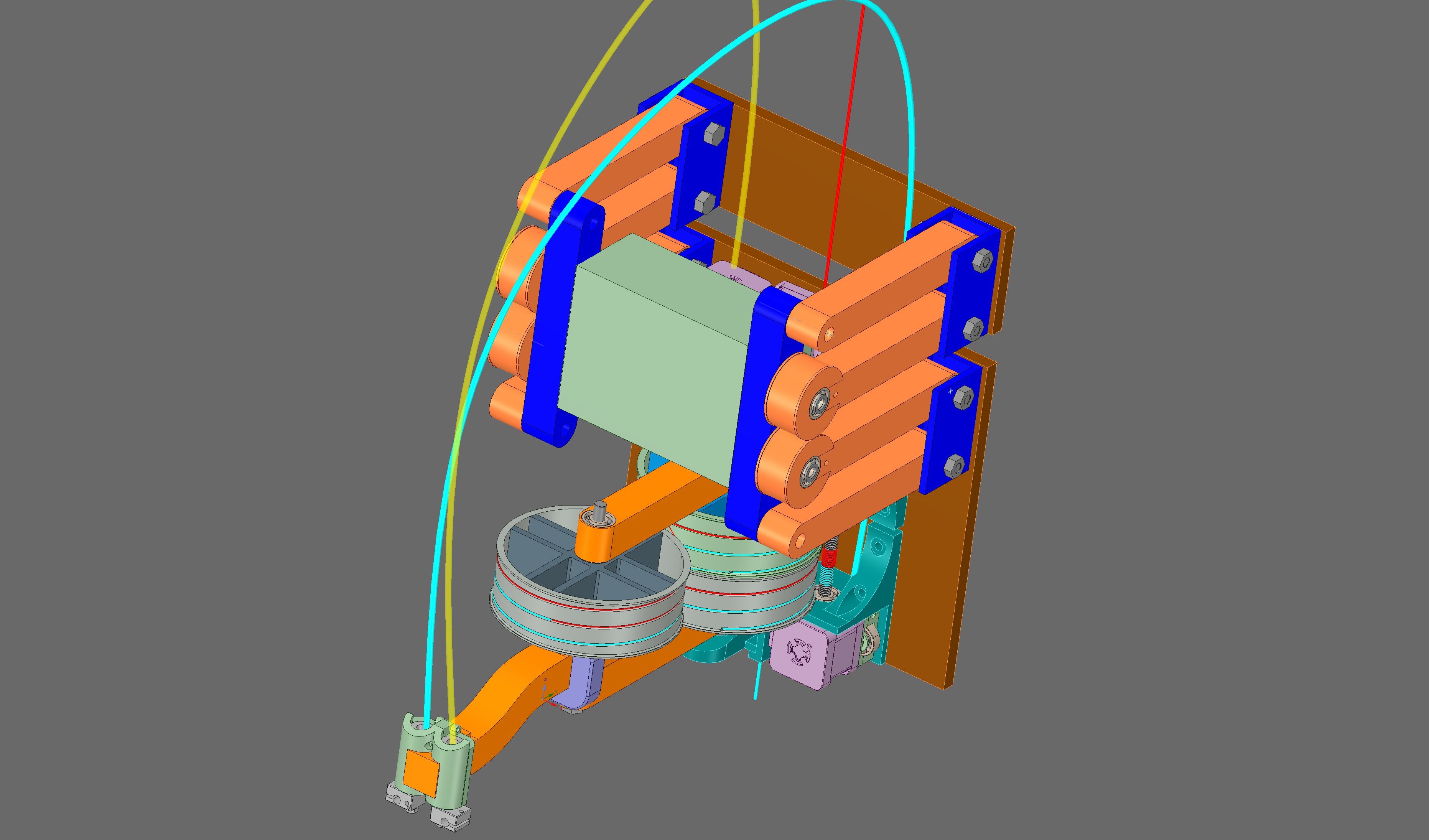
Hi, a small update... I haven't given up, still doing research and started printing parts at a friend's .... design is somewhat settled, now finer details and some collateral choices are being made like nozzle funnel, hotend case, etc.
I am frightened to see electronics time approaching and that means getting ready for Morgan firmware modification. I have also ordered some vitamins (hotends, hobbed gears, bearings, bolts/nuts/screws), still have to order the motors and the brains ...
I think I will first use a sanguinolulu board my friend is having around since he upgraded his Solidoodle.
Here's a pic of what the printer looks right now ( in the CAD form of course)
I have also briefly explored the static SCARA configuration (on the right of the picture) but so far there is something I don't like about it. Maybe I just have to get used to seeing it or thinking about this configuration.
I am frightened to see electronics time approaching and that means getting ready for Morgan firmware modification. I have also ordered some vitamins (hotends, hobbed gears, bearings, bolts/nuts/screws), still have to order the motors and the brains ...
I think I will first use a sanguinolulu board my friend is having around since he upgraded his Solidoodle.
Here's a pic of what the printer looks right now ( in the CAD form of course)

I have also briefly explored the static SCARA configuration (on the right of the picture) but so far there is something I don't like about it. Maybe I just have to get used to seeing it or thinking about this configuration.
|
Re: started designing a new mostly-plastic reprap SCARA with fishing line motion transmission and unorthodox winch for Z June 23, 2015 09:35AM |
Registered: 9 years ago Posts: 58 |
|
Re: started designing a new mostly-plastic reprap SCARA with fishing line motion transmission and unorthodox winch for Z June 23, 2015 11:18AM |
Registered: 9 years ago Posts: 1,035 |
There are no useless posts . Thanks for the kind words, I hope i'll be able to deliver.
RepRap Lander concept on Concept Forge
RepRap Lander concept on RepRap Forums
My Things, mostly experimental stuff
. Thanks for the kind words, I hope i'll be able to deliver.RepRap Lander concept on Concept Forge
RepRap Lander concept on RepRap Forums
My Things, mostly experimental stuff
|
Re: started designing a new mostly-plastic reprap SCARA with fishing line motion transmission and unorthodox winch for Z June 27, 2015 11:42AM |
Registered: 9 years ago Posts: 1,035 |
piece by piece ...
I already know what a version 2.0 has to have different... and that cold-pressing bearings into their place can crack the PLA...
More to come.
PS: that Double Parallelogram with DLCJs is massive ...
RepRap Lander concept on Concept Forge
RepRap Lander concept on RepRap Forums
My Things, mostly experimental stuff
|
Re: started designing a new mostly-plastic reprap SCARA with fishing line motion transmission and unorthodox winch for Z June 27, 2015 03:05PM |
Registered: 11 years ago Posts: 177 |
Did you consider putting the bearings in a freezer for a few hours before putting them in?
[scara3dprinter.wordpress.com]
[scara3dprinter.wordpress.com]
|
Re: started designing a new mostly-plastic reprap SCARA with fishing line motion transmission and unorthodox winch for Z June 27, 2015 03:13PM |
Registered: 9 years ago Posts: 1,035 |
I've read about that but isn't that going to stress the plastic the same when they expand? I see more logic in heating the part, thus it will evenly distribute the stress around the bearing but was too lazy to do that. I will try for the other parts the freezing method to see how it will behave.
Thanks for your input.
RepRap Lander concept on Concept Forge
RepRap Lander concept on RepRap Forums
My Things, mostly experimental stuff
Thanks for your input.
RepRap Lander concept on Concept Forge
RepRap Lander concept on RepRap Forums
My Things, mostly experimental stuff
|
Re: started designing a new mostly-plastic reprap SCARA with fishing line motion transmission and unorthodox winch for Z June 27, 2015 03:51PM |
Registered: 11 years ago Posts: 177 |
When I built my scara machine, I machined the holes to a very tight tolerance, heated the arms on a hot plate and chilled the bearings. Parts slipped together like a champ.
[scara3dprinter.wordpress.com]
[scara3dprinter.wordpress.com]
|
Re: started designing a new mostly-plastic reprap SCARA with fishing line motion transmission and unorthodox winch for Z June 27, 2015 04:16PM |
Registered: 9 years ago Posts: 1,035 |
I've read the thread about it, beautiful machine. I am thinking of a similar approach, to heat the parts on the heated bed of the printer I'm building the parts on and to use the freezer for the bearings.
BTW, I suppose you are still using it right?? I am interested in software and controller options for a SCARA. Latest i've seen on Github is a Marlin variation of Vitaminrad's from 4mo ago. I have no clue what controller can deal with SCARA computation in an optimum way, wouldn't really want to go Smoothieware, it's too expensive. Mega/Ramps 1.4 on the other hand are kinda dated ... was thinking Due/Ramps-FD ...
RepRap Lander concept on Concept Forge
RepRap Lander concept on RepRap Forums
My Things, mostly experimental stuff
|
Re: started designing a new mostly-plastic reprap SCARA with fishing line motion transmission and unorthodox winch for Z June 27, 2015 11:16PM |
Registered: 11 years ago Posts: 177 |
Try as I might, I am not much of a programmer. That printer runs off a ramps 1.4 purchased from Ultimachine. Great board in my opinion, but a bit expensive. There are knockoffs available on ebay for $40.
I'm not using it at the moment. My main printer went down so I snagged some parts off of it. I have been meaning to rebuild it, I have never been happy with the sheet steel and have long been thinking of replacing it with sheet aluminum.
Edited 1 time(s). Last edit at 06/27/2015 11:18PM by Evil Monkey.
[scara3dprinter.wordpress.com]
|
Re: started designing a new mostly-plastic reprap SCARA with fishing line motion transmission and unorthodox winch for Z June 28, 2015 09:16AM |
Registered: 9 years ago Posts: 1,035 |
I am fortunate enough to have access to a sanguinolulu board a friend has upgraded and has it lying around so I will try that with Ramps 1.4. My main goal is have it move in a correct way. I've been reading about Teacup FW and it's SCARA implementation but @theothermike has issues compiling it and having it move even the basic moves. The contributor that added the code to Teacup is nowhere to be found 
RepRap Lander concept on Concept Forge
RepRap Lander concept on RepRap Forums
My Things, mostly experimental stuff
RepRap Lander concept on Concept Forge
RepRap Lander concept on RepRap Forums
My Things, mostly experimental stuff
|
Re: started designing a new mostly-plastic reprap SCARA with fishing line motion transmission and unorthodox winch for Z June 28, 2015 10:03AM |
Registered: 9 years ago Posts: 127 |
The Marlin armlevel firmware branch by Quentin Harley might work for you....
[github.com]
I had to think about it, but although the Morgan uses two arms, it resembles the single arm kinematics...
Edited 1 time(s). Last edit at 06/28/2015 10:05AM by theothermike.
[github.com]
I had to think about it, but although the Morgan uses two arms, it resembles the single arm kinematics...
Edited 1 time(s). Last edit at 06/28/2015 10:05AM by theothermike.
|
Re: started designing a new mostly-plastic reprap SCARA with fishing line motion transmission and unorthodox winch for Z June 28, 2015 10:46AM |
Registered: 9 years ago Posts: 1,035 |
@theothermike: my bot's design is Morgan in disguise, minus the assisting arms (if I limit the arm movement to one side only). My only caveat with Quentin's fork is that is quite old, and i've read that it is in such a way made that it can't/won't be ever committed to Marlin main.
At the end of the day there aren't many options for SCARA. Unless I go smootieware.
So far my options seem to be:
1) Marlin armlevel firmware branch by Quentin Harley
2) vitaminrad/Marlin-for-Scara-Arm
3) RobertKuhlmann/Traumflug: Teacup_Firmware
It's pretty hectic reading bits and pieces everywhere and still missing a good understanding of the environment.
Edited 1 time(s). Last edit at 06/28/2015 10:47AM by realthor.
RepRap Lander concept on Concept Forge
RepRap Lander concept on RepRap Forums
My Things, mostly experimental stuff
|
Re: started designing a new mostly-plastic reprap SCARA with fishing line motion transmission and unorthodox winch for Z June 28, 2015 04:30PM |
Registered: 9 years ago Posts: 127 |
Yep,...as I said....
but I think at first one should get it running, testing the machines (mechanical) limits and afterwards (perhaps in a second design iteration) one can finetune electronics towards speed, accuracy etc....
Smoothie`s really cool, but with every additional variable things get worse.
Arduino Mega & Ramps 1.4 definitely can drive a SCARA using several different firmwares. This combo is easy2go, more or less reliable, cheap and that´s why I have chosen it for my first steps.... Nevertheless, calculation speed divided by cal.error (as figure of merit) is mostly larger=better for more powerful controllers.
Afterwards, when I´m finished with all mechanical and basic firmware issues, I might think about Smoothie or Teensy3.1... but that´s another story :-)
Go ahead with controllers you´re feeling most comfortable. ;-)


Sorry, only registered users may post in this forum.