Polar Rep Rap
Posted by galaxyman7
|
Polar Rep Rap March 10, 2010 02:06AM |
Registered: 14 years ago Posts: 198 |
Hey, I was thinking that the best way to go in order to get rid of all the metal parts in a reprap is making it polar (or spherical coordinates). This would basically be a robotic arm with an extruder on the end. The mechanical part would hardly be complicated, just needing 3 motors for rotation in 2 directions, plus an extending arm. The tricky part would be programming. But it is much better to have the programming be difficut rather than have the cost of the machine go up.
Another great thing about having a robotic arm type reprap is that it would need hardy any metal pieces. The only pieces it would need are bolts and nuts, plus some parts for the extruder. The rest could be printed.
Motors could be very geared down hobby motors, like the ones here>> robokitsworld.com, which only cost $4. These could have "encoder wheels" with holes in them where an
led and light sensor detect rotation. A microcontroller could read these signals and position the arm where needed.
By making the machine polar, it also GREATLY reduces size of the machine. It could even fold up for storage.
Plus, having a robotic arm make 3d parts for you would just be awesome.
If anyone is interested in making one with their current rep rap, I will draw up some parts in Solid Edge and post them here.
Here is an example on youtube>> [www.youtube.com]
Edit: You actually don't need an extending arm, so that eliminates the need for linear slides or anything like that.
Edited 3 time(s). Last edit at 03/10/2010 12:01PM by galaxyman7.
|
Re: Polar Rep Rap March 10, 2010 05:41AM |
Registered: 14 years ago Posts: 105 |
I agree completely.
My preference is hydraulics for such a project because they are low weight, although gear motors, and worm gears both have their merits.
[builders.reprap.org]
This was my first exposure to the idea.
This is what I'm working on.
[dev.forums.reprap.org]
[objects.reprap.org]
Beagle fury is attacking the mathematics issue, as he's already got a set of hardware.
[objects.reprap.org]
EMC2 claims it supports robotic arms(as well as stewart platforms), however you have to write your own kinematics.
The math seems like some sort of trig problem from hell.
I just finished writing toolpaths for my pinch roller extruder, and I have all the components, so I'm a couple drill bits away from repstrapping some CNC mills at which point I can start rapid prototyping the parts for the Cyberdyne T-1, T-800, and T-600.
I expect my next project is going to be a plastic recycler after having to feed this thing I'm about to create.
Good to have you on the the "team" so to speak. You may consider making your own Gada competition team, or you can help me, Beaglefury, and/or Brian Korsedal.
The gada rules imply an arm as I read them, although some of the things like the saurus linkages may end up showing otherwise.
Edited 1 time(s). Last edit at 03/10/2010 05:48AM by JohnnyCooper.
|
Re: Polar Rep Rap March 10, 2010 08:18AM |
Registered: 14 years ago Posts: 278 |
You might want to check my Re(pOlaR)ap development, or even pitch in if you want.
I've got moving XY, and am working on software to accelerate printing. I also have a few posts on the Builders blog, and a video showing simple drive motion on XY.
My goals include creating an easy to build repstrap, and create a fully printable design as well to improve some areas (geared motors).
The dual disk design is mathematically isomorphic to a two link arm system, but the advantages include simpler physical componenents at the cost of a larger footprint for equivilant print area.
|
Re: Polar Rep Rap March 10, 2010 08:23AM |
Admin Registered: 16 years ago Posts: 13,884 |
... look at the wafer-handling robots - here you have 2 or 3 arms (or 2 arms parallelized for higher accuracy) ...
Viktor
--------
Aufruf zum Projekt "Müll-freie Meere" - [reprap.org] -- Deutsche Facebook-Gruppe - [www.facebook.com]
Call for the project "garbage-free seas" - [reprap.org]
Viktor
--------
Aufruf zum Projekt "Müll-freie Meere" - [reprap.org] -- Deutsche Facebook-Gruppe - [www.facebook.com]
Call for the project "garbage-free seas" - [reprap.org]
|
Re: Polar Rep Rap March 10, 2010 11:46AM |
Registered: 14 years ago Posts: 198 |
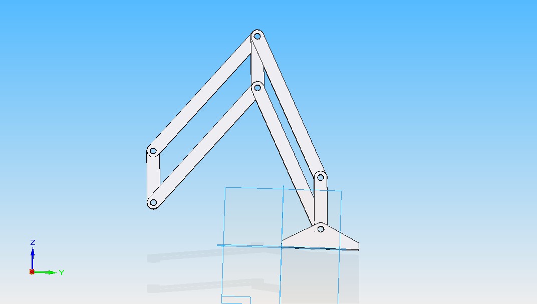
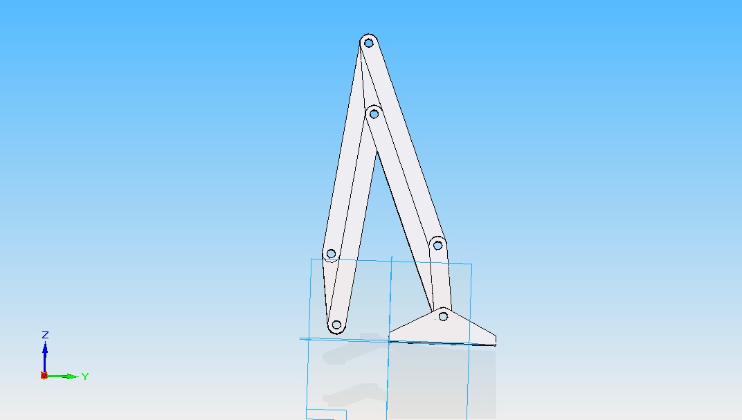
Ok, it looks like Johnny Cooper's team has already thought of a dual rotating platform, which is interesting, but I do not see any z axis movement being very easy on that machine. The robotic arm will have no linear slides, only rotation. Plus it can rotate in a full circle, making parts anywhere around itself. This means it could theoretically print all of its parts in one go! I have experimented in Solid Edge to see how I can make things work, and it has been fairly straightforward. Here are some pics. It really is not as complicated as you think.
I have not added the base rotation yet but I will
I have not added the base rotation yet but I will
|
Re: Polar Rep Rap March 10, 2010 11:57AM |
Registered: 14 years ago Posts: 198 |
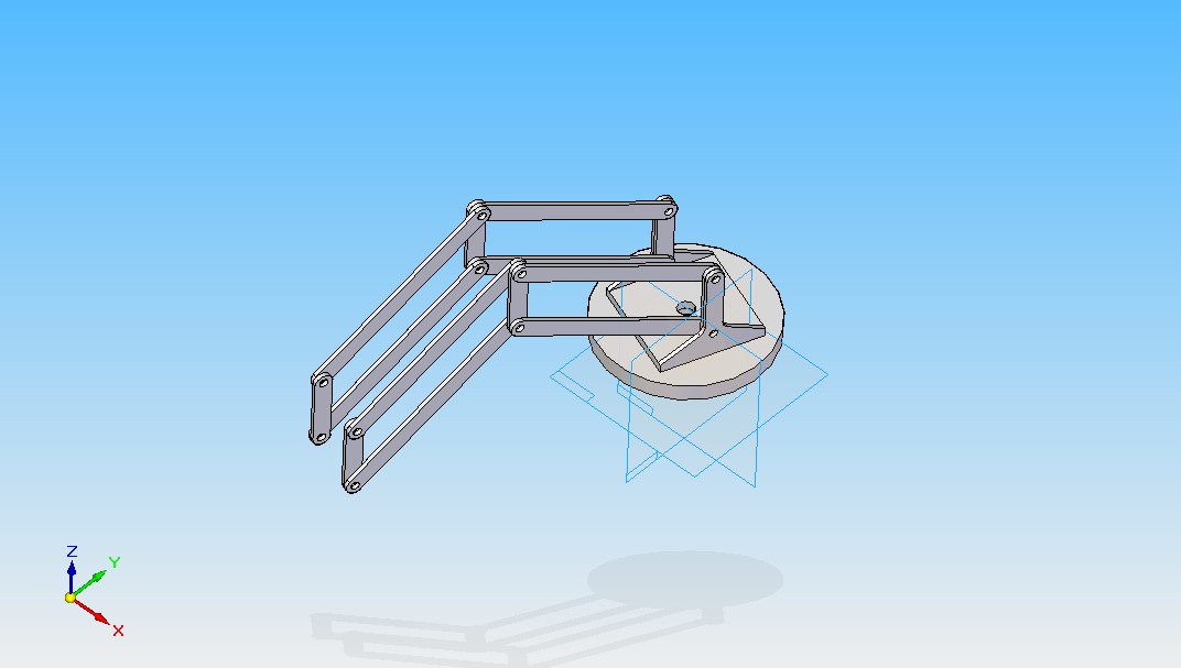
Here are some more pics with the base rotating. I also made the link at the base rigid.
Obviously things would need to be thicker in order to hold the motors and extruder, but this just shows the basic concept. I think 3 linkages in parallel would probably be best, with the top linkages being thicker to hold the motors.
Also not shown in the pics are the pins that connect the two linkages, which would just be bolts.
Edited 2 time(s). Last edit at 03/10/2010 12:04PM by galaxyman7.
|
Re: Polar Rep Rap March 10, 2010 01:21PM |
Registered: 14 years ago Posts: 105 |
galaxyman7 Wrote:
-------------------------------------------------------
> Ok, it looks like Johnny Cooper's team has already
> thought of a dual rotating platform, which is
> interesting, but I do not see any z axis movement
> being very easy on that machine. The robotic arm
> will have no linear slides, only rotation. Plus it
> can rotate in a full circle, making parts anywhere
> around itself. This means it could theoretically
> print all of its parts in one go! I have
> experimented in Solid Edge to see how I can make
> things work, and it has been fairly
> straightforward. Here are some pics. It really is
> not as complicated as you think.
>
> I have not added the base rotation yet but I will
Dual rotating platform is actually Beaglefury.
Would love to take credit for it, because it really is a work of genius IMHO.
|
Re: Polar Rep Rap March 10, 2010 03:08PM |
Registered: 14 years ago Posts: 198 |
Ahh, ok. Credit goes to Beaglefury.
I am going to do some calculations to find the relationship between the x, y, and z position compared to the angle of rotation for each joint. Then this can be used to position the arm. The only thing I am worried about is the motors overshooting their target. They need to be started and stopped exactly at each angle. Got any ideas? I know if you short the motor out it will brake the motor, but how effective is that? Also, you can ramp the motors so they stop on target, but that would require a more complicated program.
I am going to do some calculations to find the relationship between the x, y, and z position compared to the angle of rotation for each joint. Then this can be used to position the arm. The only thing I am worried about is the motors overshooting their target. They need to be started and stopped exactly at each angle. Got any ideas? I know if you short the motor out it will brake the motor, but how effective is that? Also, you can ramp the motors so they stop on target, but that would require a more complicated program.
|
Re: Polar Rep Rap March 10, 2010 06:14PM |
Registered: 14 years ago Posts: 278 |
galaxyman7 Wrote:
--------------------------------------------------
> but I do not see any z axis
> movement
> being very easy on that machine.
I've considered a polar z axis as well. Until I get everything in X and Y, I decided to table that work, since worst case, I could use a linear bearing and threaded rod drive for that stage -- there is no great need for speed. One problem I ran into with a polar Z is that the extruder may not remain orthogonal to the print surface as it is raised or lowered. Creating a linkage system might be required.
> I am going to do some calculations to find the relationship between the x, y, and z position compared to the angle of rotation for each joint.
The two arm solution can be expressed in closed form; I'm not so sure about all configurations of 3 arms, but probably for configurations that you would consider, they should be solvable.
In terms of what the angle relations look like, for 2 planer angles, constant rotation generate Rose Curves. Adding an incline link would simply generate rose curves with a trigonometric 'zoom' scale.
You might also want to take a look at the image I generated that shows the 'grid' of the two link arms. If you change the angle on one link, while fixing the angle on the other, you'll trace out the lines in these images (I still didn't fix the one on the left.. it still looks wrong to me, so ignore that one, and just look at the one on the right. )
)
UPDATED: I double checked the topology on the left, and it too is correct. I guess optical illusions played with my mind in terms of thinking it not correct. This shows the model space if one link in a two link pair is shorter or longer than the other for the full 360 degree rotation on one link, and 180 degree on the second link (Another 180 degree on the second link wraps back into the same model space volume, so I excluded it when displaying the grid pattern.)
Edited 1 time(s). Last edit at 03/10/2010 07:01PM by BeagleFury.
--------------------------------------------------
> but I do not see any z axis
> movement
> being very easy on that machine.
I've considered a polar z axis as well. Until I get everything in X and Y, I decided to table that work, since worst case, I could use a linear bearing and threaded rod drive for that stage -- there is no great need for speed. One problem I ran into with a polar Z is that the extruder may not remain orthogonal to the print surface as it is raised or lowered. Creating a linkage system might be required.
> I am going to do some calculations to find the relationship between the x, y, and z position compared to the angle of rotation for each joint.
The two arm solution can be expressed in closed form; I'm not so sure about all configurations of 3 arms, but probably for configurations that you would consider, they should be solvable.
In terms of what the angle relations look like, for 2 planer angles, constant rotation generate Rose Curves. Adding an incline link would simply generate rose curves with a trigonometric 'zoom' scale.
You might also want to take a look at the image I generated that shows the 'grid' of the two link arms. If you change the angle on one link, while fixing the angle on the other, you'll trace out the lines in these images (I still didn't fix the one on the left.. it still looks wrong to me, so ignore that one, and just look at the one on the right.
)UPDATED: I double checked the topology on the left, and it too is correct. I guess optical illusions played with my mind in terms of thinking it not correct. This shows the model space if one link in a two link pair is shorter or longer than the other for the full 360 degree rotation on one link, and 180 degree on the second link (Another 180 degree on the second link wraps back into the same model space volume, so I excluded it when displaying the grid pattern.)
Edited 1 time(s). Last edit at 03/10/2010 07:01PM by BeagleFury.
|
Re: Polar Rep Rap March 10, 2010 06:55PM |
Registered: 14 years ago Posts: 278 |
Oh, and just looked at the linkage systems you propose. Would be interesting, but not sure how you'd get the stiffness needed without good bearings.
In terms of model space, take the image I posted, cut a quadrant from it, and then rotate it around in 3D, and that should give you the topology for the rotating base, with a two link planar system for height and radius degree of freedom..
In terms of model space, take the image I posted, cut a quadrant from it, and then rotate it around in 3D, and that should give you the topology for the rotating base, with a two link planar system for height and radius degree of freedom..
|
Re: Polar Rep Rap March 11, 2010 01:44AM |
Registered: 14 years ago Posts: 198 |
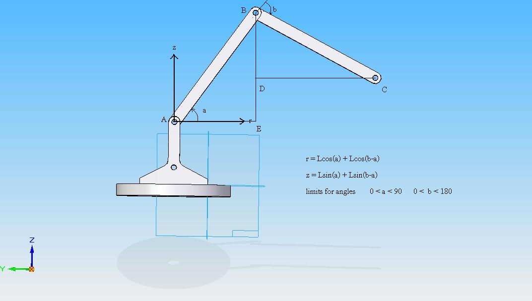
Very interesting! I have done many calculations trying to solve the angles of each member in terms of x, y , and z. It has proved to be very difficult. I have attached a picture of what I am doing. It includes the equations. First I solve for r and z, which are fairly easy. All I have to do is add up components of the lengths using trig. This converts it to cylindrical form.
-Each angle is positive in the counter clockwise direction
-Assuming the lengths are the same = L
Now once I have r and z, x= r*cos(theta), y=r*sin(theta), and z stays the same.
(converting from cylindrical to rectangular)
So in all I have 3 equations and 3 unknowns (a, b, theta). They look like this.
x= (Lcos(a)+Lcos(b+a))cos(theta)
y= (Lcos(a)+Lcos(b+a))sin(theta)
z= Lsin(a)+Lsin(b+a)
I have solved for theta, which is pretty easy, it is just tan(theta)= y/x
so theta= arctan(y/x)
I have tried using Maple to solve this, but I do not know how to set it so that the answer is only in the specified range (on the picture). When I do solve it, it comes up with a gigantic equation. I don't mind a gigantic equation, it is just that it gives me multiple answers because the range is not specified.
So if anyone could solve this system for me or tell me how to use Maple to do it, that would be awesome.
By the way, the linkage of the arms is hidden for simplicity
Edited 1 time(s). Last edit at 03/11/2010 01:46AM by galaxyman7.
|
Re: Polar Rep Rap March 11, 2010 02:07AM |
Registered: 14 years ago Posts: 198 |
|
Re: Polar Rep Rap March 11, 2010 03:35AM |
Registered: 14 years ago Posts: 198 |
Wow, I just found a paper explaining the mathematics of robotic arms! This is exactly what I was looking for. I have attached it. It is in x, y coordinates, which for me is r, z coordinates. So I will still need to do some work on it.
Edited 1 time(s). Last edit at 03/11/2010 03:57AM by galaxyman7.
Edited 1 time(s). Last edit at 03/11/2010 03:57AM by galaxyman7.
|
Re: Polar Rep Rap March 11, 2010 08:32AM |
Registered: 14 years ago Posts: 278 |
galaxyman7 Wrote:
-------------------------------------------------------
> Wow, I just found a paper explaining the
> mathematics of robotic arms! This is exactly what
> I was looking for. I have attached it. It is in x,
> y coordinates, which for me is r, z coordinates.
> So I will still need to do some work on it.
Law of cosine is awesome if you want to solve for angles given the side lengths.
If you have three points on your arm, A, B, and C, and know the lengths between each side, and need to solve for an angle, say angle ABC, simply solve the law of cosines identity for the angle:
1. AC^2 = AB^2 + BC^2 - 2 * AB * BC * cos(ABC)
2. AC^2 - AB^2 - BC^2 = 2 * AB * BC * cos(ABC)
3. ( AC^2 - AB^2 - BC^2 = 2 * AB * BC ) = cos(ABC)
4. acos( ( AC^2 - AB^2 - BC^2 ) / ( 2 * AB * BC ) ) = ABC
Take care though, acos is multivalued (as well as atan, which is also used when you need to compute angles to a specific x,y,z). Make sure you choose the branch cut appropriate to the solution desired (otherwise, your motor motion might travel in the wrong direction to get to the target angle.)
Giving a rough outline for the 3 degree of freedom robot arm you proposed,
1. given x,y,z, solve for the distance from the base point to the point
= sqrt(x^2+y^2+z^2).
2.This gives you the third side for the triangle formed by the two arms.
= motor angle 1
3. Solve for the angle on the right triangle formed by the x,y,z point, and the build plane. atan2(z,sqrt(x^2+y^2)) works.
4. Solve for the angle at the base point for the triangle created at step 2, using another law of cosines rule application.
5. Add the angles from step 3 and 4 together.
= motor angle 2.
6. The final angle is the easy one. Simply find the angle formed by x and y, using atan2.
= motor angle 3.
|
Re: Polar Rep Rap March 11, 2010 02:24PM |
Registered: 14 years ago Posts: 198 |
Yep, I had forgot about law of cosines and sines, mostly because things are usually right triangles. They are very usefull indeed. This should help a ton.
Next probem-
making a program to load the gcode and output step and direction code to the motors. This could either be done on the computer or on a microcontroller. I am thinking that the SX chip from parallax is a good option. They are only $3 and fairly easy to program since they give you a basic to assembly compiler.
The micro controller would read the position of the motors by an encoder wheel with black and white stripes printed onto it. The black and white stripes could have a gradient of gray printed inbetween, so that the microcontroller can read the value and know how far it is from the next "step". A light sensor would read the value on the wheel and change resistance. The resistance can be measured with an RC time circuit. This encoder wheel would need to spin much faster than the actual motor in order to get high accuracy, so that would have to be connected to the motor with reducing gears. This way for every 360 degrees the motor turns, the encoder wheel will turn 1040 degrees or something like that.
Also, I still need to find a solution for stopping the arm right on target. I think ramping might be the best way, since an abrupt start and stop would most likely make the arm oscillate back and forth. This means the microcontroller would need to store future step and direction signals to see when it needs to slow down, kind of like a buffer.
|
Re: Polar Rep Rap March 12, 2010 01:45AM |
Registered: 14 years ago Posts: 198 |
Equations for angles a, B, and theta (plus some inbetween equations)
B = arccos((R^2 + Z^2 -L1^2 -L2^2)/(2*L1*L2))_____-180 < B < 0
a = arccos(R/sqrt(R^2 + Z^2)) + C _____0 < a < 90
theta= arctan(y/x) Note: two answers for theta, pick right one in program
supporting equations
C = arcsin(L2*sin( B ))/sqrt(R^2 + Z^2) _____0 < C < 90
R = abs(x/arctan(y/x))_____ abs value because R can never be negative
Edited 1 time(s). Last edit at 03/12/2010 01:50AM by galaxyman7.
|
Re: Polar Rep Rap March 12, 2010 10:27AM |
Registered: 14 years ago Posts: 105 |
Another option to consider for position feedback is a potentiometer, or magnetic rotary encoder.
An infared camera at the end of the arm could maybe be used in combination with computer vision software and IR LEDS around the print bed to find position, although this may have lag issues. One nice thing about a polar bot like this is I can see it being used as a Coordinate Measuring MAchine. A 3D laser scanner would be a nice feature as well.
An infared camera at the end of the arm could maybe be used in combination with computer vision software and IR LEDS around the print bed to find position, although this may have lag issues. One nice thing about a polar bot like this is I can see it being used as a Coordinate Measuring MAchine. A 3D laser scanner would be a nice feature as well.
|
Re: Polar Rep Rap March 12, 2010 10:46AM |
Registered: 14 years ago Posts: 278 |
galaxyman and I have sent a few pm's back and forth for collaberation.
I think it would be great to create a blog/wiki/forum specific for discussion and collaberation, relating to the software needs for non-linear mechanics. Anyone want to volunteer?
Given this, I will post all the details of what I've done so far in software, with details in terms of math and equations and strategy and approach. Anyone who has also taken steps to attack this could also do similarly, and we can then start collaberating and creating software that could manage any polarbot configuration, be it dual disk, 2 link rotating arm, or delta bot.
My current efforts include:
spline interpretation firmware (C++)
math, formulas, and logic to convert one set of data points (cartesion biased) into a second set of data points (angle biased) (C#)
I do use C# instead of java, since that is what I use professionally, and will find the best efficiency. I don't believe it would be too difficult to port or convert to java if necessary (I use LINQ, so some helper classes might be needed.)
|
Re: Polar Rep Rap March 12, 2010 03:04PM |
Registered: 14 years ago Posts: 198 |
One big thing is that the program needs to be user friendly. I have used Skeinforge and it is ridiculous how many other things you need to download to use it. Plus after all that, it wouldn't even load my stl files. So please, if you can, make a nice GUI interface with clear steps that anyone can understand.
I will mill out the arm pieces today, out of some polycarbonate I have laying around. I am thinking that the arms will be 6 inches each, and the connecting links will be 2 inches. If we need to later, we can print a bigger machine for the contest, however a longer arm will mean the motors will need more torque.
One thing is, how heavy are the extruders? Can anyone weigh theirs to see? The lighter the extruder, the smaller motors we can use.
I assumed the extruder was 2 lb, which seems a bit heavy but I would like to overcompensate. The max torque required for the lower arm motor with this weight is 24 lb- in. There is a motor at robokitsworld that is 10 RPM, 10 lb-in, for $5. So, we can actually gear one of these motors down 9:1 using two gears, and get around 1 RPM and 100 lb-in! This should be plenty of speed and torque. (Although I am pretty sure the gears would break at 100 lb -in) And these ratings are for 4v! I have driven these motors at 12V before and they go 3 times as fast with increased torque. This means we could power these motors with 12 V and get around 3 RPM and 150 lb in.
|
Re: Polar Rep Rap March 12, 2010 04:33PM |
Registered: 14 years ago Posts: 105 |
[blog.reprap.org]
The Bowden Paste extruder might be the way to go for the prototype.
Speaking of light weight extruders:
[letsmakerobots.com]
[www.roboternetz.de]
[hackedgadgets.com]
These delta bots are stupid easy to fabricate. You can make the structure from carbon fiber rod, and their universal joints can be made on a lathe with a radiusing tool and a ball end mill. Or: 2 hinges to get even simpler.
They don't even have to be press fit. You can hold opposing joints together with springs.
The elbow design is more complicated than it needs to be. You can go without by placing 3 linear rails in place of them at an angle. Of course: 3 hobby servos plus elbows would be the ideal way to get your feet wet, and you could have 3 hobby servos and some laser cut acrylic made for virtually nothing.
I'm going to update my blog in the next 48 hours on my progress with making a tool to hold worm wheels in a lathe for hobbing. That's one way we could go about getting the torque to the required level for a polar bot.
Cheers,
-Johnny
Edited 1 time(s). Last edit at 03/12/2010 04:45PM by JohnnyCooper.
|
Re: Polar Rep Rap March 12, 2010 05:06PM |
Admin Registered: 17 years ago Posts: 1,791 |
I'm going to update my blog in the next 48 hours on my progress with making a tool to hold worm wheels in a lathe for hobbing. That's one way we could go about getting the torque to the required level for a polar bot.
Would you like to put it up on the wiki?
-Sebastien, RepRap.org library gnome.
Remember, you're all RepRap developers (once you've joined the super-secret developer mailing list), and the wiki, RepRap.org, [reprap.org] is for everyone and everything!
Would you like to put it up on the wiki?
-Sebastien, RepRap.org library gnome.
Remember, you're all RepRap developers (once you've joined the super-secret developer mailing list), and the wiki, RepRap.org, [reprap.org] is for everyone and everything!
|
Re: Polar Rep Rap March 12, 2010 05:15PM |
Registered: 14 years ago Posts: 198 |
Here are some pictures of the first linkage system I milled out. It seems to be pretty sturdy when I try to bend it downwards, but obviously it is wobbly back and forth. I need to make a base to hold two of these side by side, and then put bolts through both of them. That should definetly be sturdy enought to hold an extruder. I also need to make mounts for the motors on the arm and in the base.
|
Re: Polar Rep Rap March 12, 2010 05:31PM |
Admin Registered: 17 years ago Posts: 1,791 |
I think it would be great to create a blog/wiki/forum specific for discussion and collaberation, relating to the software needs for non-linear mechanics. Anyone want to volunteer?
We've got
[objects.reprap.org]
and it will take once people need to start uploading pictures and parts files to it.
Also, don't forget to that we need to create wiki pages for own projects, [[Big_Delta]], [[TeamX_Delta]], [[My_Delta]] once we feel they've outgrown that Delta page. [objects.reprap.org]
And I'll try to find the time tonight to create a dedicated Delta forum. Testing the new blog extension for mediawiki will take a little while longer.
People are welcome to post stuff on their own blogs, or even create new blogs. (Hundreds of them. It's sort of RepRap 'nesting behavior'.) It may be more useful to coordinate in the new delta forum, and also on that wiki.
-Sebastien, RepRap.org library gnome.
Remember, you're all RepRap developers (once you've joined the super-secret developer mailing list), and the wiki, RepRap.org, [reprap.org] is for everyone and everything!
|
Re: Polar Rep Rap March 12, 2010 05:56PM |
Registered: 14 years ago Posts: 278 |
> We've got
> [objects.reprap.org]
> and it will take once people need to start
> uploading pictures and parts files to it.
Actually, I was looking for something more suited to multi-person development and collaberation, and also, more general than for a specific robot.
The strategy I'm employing does not care what the mapping functions are, be they arcos, exp, log, or whatever. It only requires they be continuous, differentiable up to the 3rd degree, and well defined.
So, if you start with X (t),Y (t),Z (t),E (t),Temp (t) (the standard 5D controls), and use GCode to specify the path you want, you simply get a function thru time (perhaps 2 hours) consisting of several thousand straight line segment. My algorithm will take these, perform a transformation to a different model topology (2 or 3 polar axes, E(t), and Temp(t)), and then optimize the path so it builds as fast as possible given constraints on each axes velocity, acceleration and jerk... so, it will take the 2 hour build time on a rudementary cartesion layout, and produce a 1 hour optimized build of several thousand 3rd degree cubic spline segments suitable to run on your cartesion bot, polar bot, delta bot, or RepOlaRap. Cartesion bots can get away without doing this as much because they don't have to worry about curvy lines.. they can simply say if you move 1 mm on X, you better make sure you move 2 mm on Y. Polar bots don't have this advantage.
What I see is a libray where you write a little bit of code to say, "If I want to be at X,Y,Z, my robot motors should be at position A, B, and C", and it does all the hard work of figuring out optimal accelerations thru the rough spots, keeping vibration down, and moving everything as fast as mechanically possibly (or at least, to as fast as you were able to constrain it so you always got reliable prints.)
The easy part is the mapping from XYZ to angles ... worst case, you just use an adaptive iterative approximation for each point. The harder part is figuring out that you can race motor 1 at 300 RPM only for 1 seconds before you better start slowing down for the approaching corner, so you don't overshoot your target by 3mm because your bearings and bracing can't handle the jerk that produces.
It may be that what I propose is overkill, or not needed. In that case, perhaps there is no need to collaberate on it.
|
Re: Polar Rep Rap March 12, 2010 06:09PM |
Registered: 14 years ago Posts: 105 |
Sent this to a Delta bot creator, thought it was worth mentioning in this thread as well.
It may of course be the robotic arm which does the printing/?milling?/laser cutting ect. depending on the needs, but I don't see them as seperate projects but as individual components in a self replicating factory.
Quote
Something you may be interested in is the blog post today on the "bowden paste extruder" which uses what seems to be two syringes as a hydraulic linkage to drive the paste. Incredibly light weight. Should be easy to affix to your delta bot as a competitor in the "Gada Prize Competition" If you could print replacement linkages and joints I'd say you'd have a good chance of winning.
The technique combined with a robotic arm, and a rotating print surface could give you an entire factory. The delta could be used to pick and place circuit boards, print them, and print it's own structural elements, and the robotic arm can do the assembly/supply the delta with more paste.
It may of course be the robotic arm which does the printing/?milling?/laser cutting ect. depending on the needs, but I don't see them as seperate projects but as individual components in a self replicating factory.
|
Re: Polar Rep Rap March 12, 2010 06:12PM |
Registered: 14 years ago Posts: 105 |
BeagleFury Wrote:
-------------------------------------------------------
> > We've got
> > [objects.reprap.org]
> > and it will take once people need to start
> > uploading pictures and parts files to it.
>
> Actually, I was looking for something more suited
> to multi-person development and collaberation, and
> also, more general than for a specific robot.
>
> The strategy I'm employing does not care what the
> mapping functions are, be they arcos, exp, log, or
> whatever. It only requires they be continuous,
> differentiable up to the 3rd degree, and well
> defined.
>
> So, if you start with X (t),Y (t),Z (t),E (t),Temp
> (t) (the standard 5D controls), and use GCode to
> specify the path you want, you simply get a
> function thru time (perhaps 2 hours) consisting of
> several thousand straight line segment. My
> algorithm will take these, perform a
> transformation to a different model topology (2 or
> 3 polar axes, E(t), and Temp(t)), and then
> optimize the path so it builds as fast as possible
> given constraints on each axes velocity,
> acceleration and jerk... so, it will take the 2
> hour build time on a rudementary cartesion layout,
> and produce a 1 hour optimized build of several
> thousand 3rd degree cubic spline segments suitable
> to run on your cartesion bot, polar bot, delta
> bot, or RepOlaRap. Cartesion bots can get away
> without doing this as much because they don't have
> to worry about curvy lines.. they can simply say
> if you move 1 mm on X, you better make sure you
> move 2 mm on Y. Polar bots don't have this
> advantage.
>
> What I see is a libray where you write a little
> bit of code to say, "If I want to be at X,Y,Z, my
> robot motors should be at position A, B, and C",
> and it does all the hard work of figuring out
> optimal accelerations thru the rough spots,
> keeping vibration down, and moving everything as
> fast as mechanically possibly (or at least, to as
> fast as you were able to constrain it so you
> always got reliable prints.)
>
> The easy part is the mapping from XYZ to angles
> ... worst case, you just use an adaptive iterative
> approximation for each point. The harder part is
> figuring out that you can race motor 1 at 300 RPM
> only for 1 seconds before you better start slowing
> down for the approaching corner, so you don't
> overshoot your target by 3mm because your bearings
> and bracing can't handle the jerk that produces.
>
> It may be that what I propose is overkill, or not
> needed. In that case, perhaps there is no need to
> collaberate on it.
Would sourceforge be the way to go? Seems like you're developing kinematics libraries/interpretters for EMC2. Is that off base?
|
Re: Polar Rep Rap March 12, 2010 06:13PM |
Registered: 14 years ago Posts: 105 |
SebastienBailard Wrote:
-------------------------------------------------------
> I think it would be great to create a
> blog/wiki/forum specific for discussion and
> collaberation, relating to the software needs for
> non-linear mechanics. Anyone want to volunteer?
>
> We've got
> [objects.reprap.org]
> and it will take once people need to start
> uploading pictures and parts files to it.
>
> Also, don't forget to that we need to create wiki
> pages for own projects, [], [], [] once we feel
> they've outgrown that Delta page.
> [objects.reprap.org]
>
> And I'll try to find the time tonight to create a
> dedicated Delta forum. Testing the new blog
> extension for mediawiki will take a little while
> longer.
>
> People are welcome to post stuff on their own
> blogs, or even create new blogs. (Hundreds of
> them. It's sort of RepRap 'nesting behavior'.)
> It may be more useful to coordinate in the new
> delta forum, and also on that wiki.
I've gone ahead and made this: [objects.reprap.org]
Would a forum for delta bots, and a forum for polar bots be possible? The Repstrappers forum already has a decent amount of discussion on delta bots, so there seems to be demand there.
|
Re: Polar Rep Rap March 12, 2010 06:24PM |
Registered: 14 years ago Posts: 198 |
|
Re: Polar Rep Rap March 12, 2010 06:48PM |
Registered: 14 years ago Posts: 278 |
|
Re: Polar Rep Rap March 12, 2010 07:11PM |
Registered: 14 years ago Posts: 198 |
Here are the ranges for a robotic arm type printer with two 6 inch arms (like the one in the photo I took). It is a kind of dog bowl type shape.
This should be able to print its own parts easily
Edited 1 time(s). Last edit at 03/12/2010 07:12PM by galaxyman7.
This should be able to print its own parts easily
Edited 1 time(s). Last edit at 03/12/2010 07:12PM by galaxyman7.

Sorry, only registered users may post in this forum.