Delta Scara - 3D printer design
Posted by simspeed
|
Delta Scara - 3D printer design June 26, 2014 07:21PM |
Registered: 10 years ago Posts: 169 |
Hello to the forum...
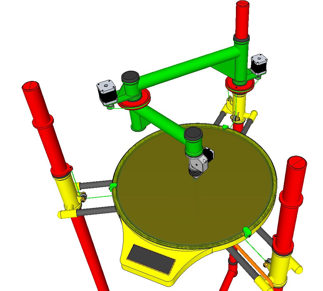
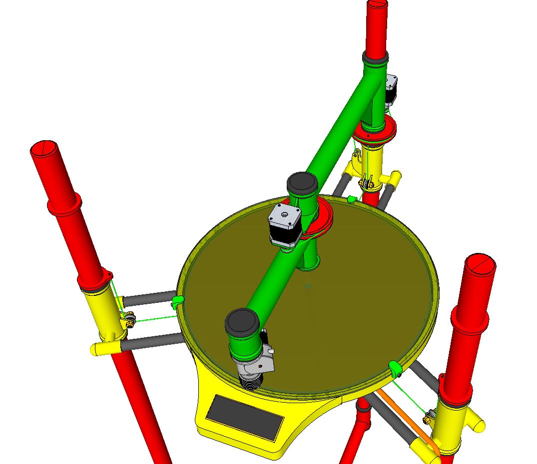
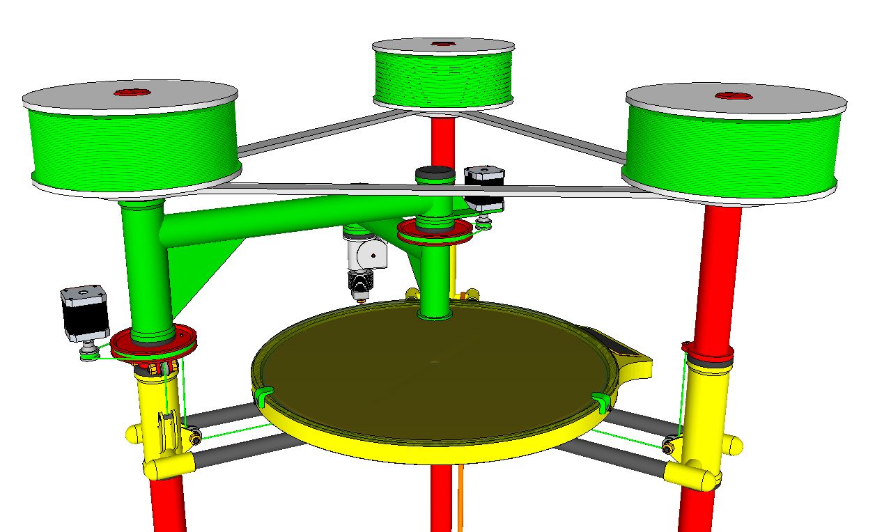
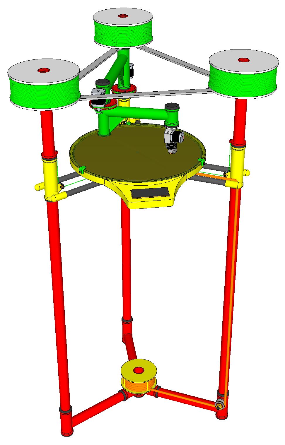
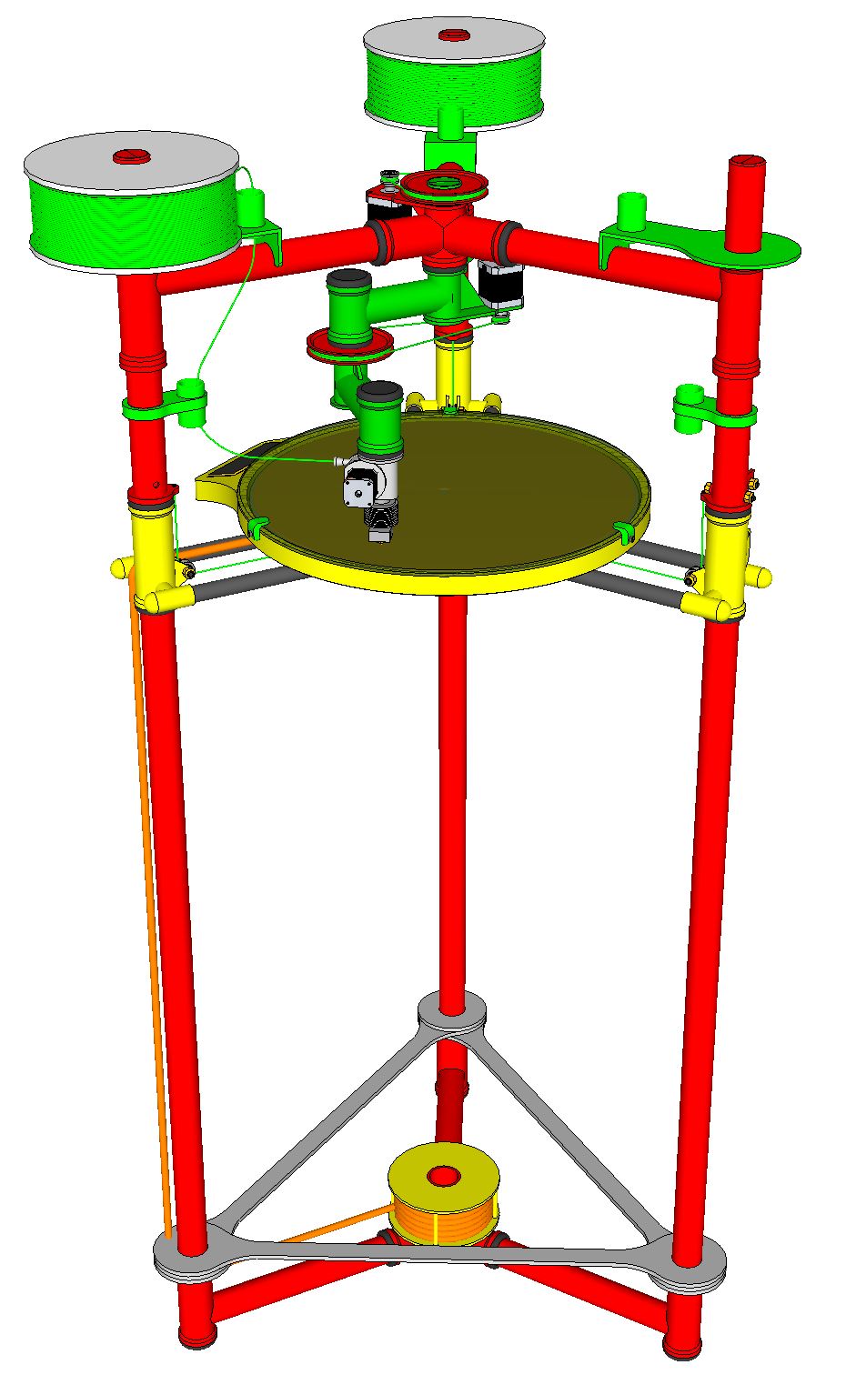
I've been working to design a large print volume 3D printer based on a Delta frame platform. I've progressed through numerous ideas and iterations for the three axis movements and believe I've settled on the following shown here. I've bounced ideas off Nicholas Seward and he's been more than gracious with his time and advice. I've decided to post these drawings of the latest design and ask for your feedback. To clarify, I have no background in electronics. My experience I'm applying here is general fabrication in metalcraft, welding, and racecar chassis building.
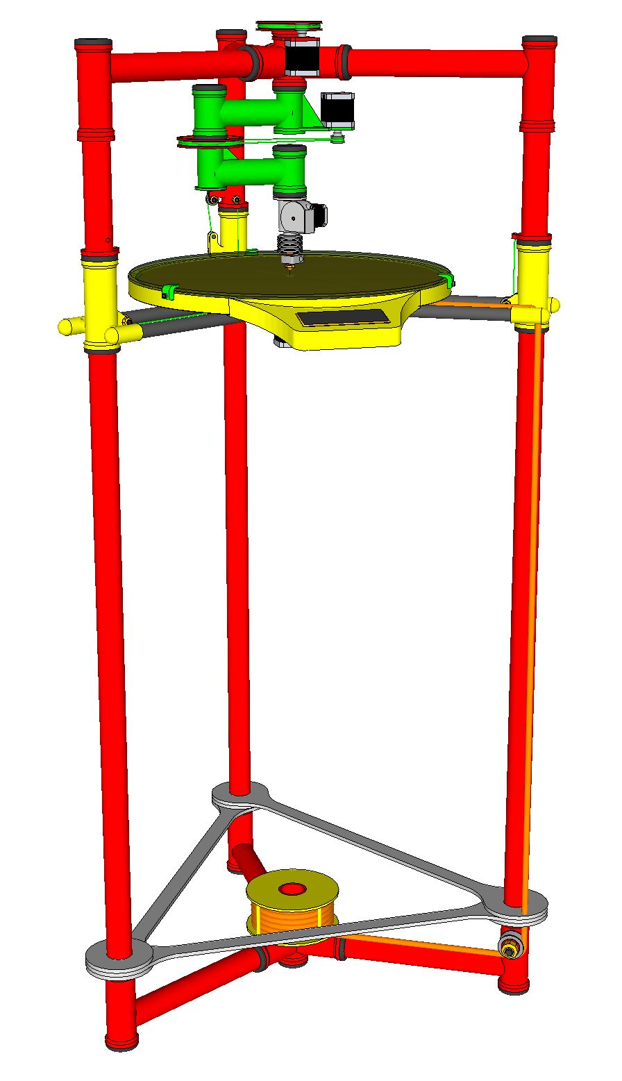
This printer chassis is designed to use 1.5" thin wall 4130 chromoly tubing for the vertical risers. The Z axis slides will use 1.875" milled tubing and delrin bearings set in 3D printed races. The bed carriage is CF tubing and 3D printed hub. All tubing will be powder coated to dimension for the slides. I was originally going to tig the frame all up for my use, but I've found a way to clamp all the fittings so it will break down for easy packaging in the event I decide to manufacture for sale. The bed diameter is approx. 18". The Z height can be almost anything. The drawings show a 473 X 900mm print envelope.
The scara arm seems to be the easiest design to implement and fabricate out of the number of different ideas I've considered. I believe the structure will provide adequate stiffness so droop shouldn't be a problem. The scara arm will swivel on machined steel ball bearings at both hinge points. The arm sections can be fabricated from aluminum or CF for weight savings. I've drawn string drives for all the axis but the arm may require belts to control momentum. The extruder is an idea based on posts here in the forum by CNC Dick that uses mig welder drive wheels. I'm familiar with those and I agree with CNC Dick that larger diameter drive wheels are needed. The hot end and extruder also swivel in the arm end to keep alignment with the wire spool as the arm moves about the table.
I'll need to find and do a joint venture with an electronics specialist who can configure the control systems based on these movements. I plan to construct the chassis and all the mechanicals before bringing in the electronics guy/gal....whoever.
Your thoughts...ideas...critique....criticisms? Much obliged.
Terry Peterson
I've been working to design a large print volume 3D printer based on a Delta frame platform. I've progressed through numerous ideas and iterations for the three axis movements and believe I've settled on the following shown here. I've bounced ideas off Nicholas Seward and he's been more than gracious with his time and advice. I've decided to post these drawings of the latest design and ask for your feedback. To clarify, I have no background in electronics. My experience I'm applying here is general fabrication in metalcraft, welding, and racecar chassis building.
This printer chassis is designed to use 1.5" thin wall 4130 chromoly tubing for the vertical risers. The Z axis slides will use 1.875" milled tubing and delrin bearings set in 3D printed races. The bed carriage is CF tubing and 3D printed hub. All tubing will be powder coated to dimension for the slides. I was originally going to tig the frame all up for my use, but I've found a way to clamp all the fittings so it will break down for easy packaging in the event I decide to manufacture for sale. The bed diameter is approx. 18". The Z height can be almost anything. The drawings show a 473 X 900mm print envelope.
The scara arm seems to be the easiest design to implement and fabricate out of the number of different ideas I've considered. I believe the structure will provide adequate stiffness so droop shouldn't be a problem. The scara arm will swivel on machined steel ball bearings at both hinge points. The arm sections can be fabricated from aluminum or CF for weight savings. I've drawn string drives for all the axis but the arm may require belts to control momentum. The extruder is an idea based on posts here in the forum by CNC Dick that uses mig welder drive wheels. I'm familiar with those and I agree with CNC Dick that larger diameter drive wheels are needed. The hot end and extruder also swivel in the arm end to keep alignment with the wire spool as the arm moves about the table.
I'll need to find and do a joint venture with an electronics specialist who can configure the control systems based on these movements. I plan to construct the chassis and all the mechanicals before bringing in the electronics guy/gal....whoever.
Your thoughts...ideas...critique....criticisms? Much obliged.
Terry Peterson
Attachments:
open | download - Delta Scara 011.JPG (108.7 KB)
open | download - Delta Scara 012.JPG (104.7 KB)
open | download - Delta Scara 013.JPG (103.2 KB)
open | download - Delta Scara 014.JPG (125 KB)
open | download - Delta Scara 015.JPG (130 KB)
open | download - Delta Scara 016.JPG (148.1 KB)
open | download - Delta Scara 011.JPG (108.7 KB)
open | download - Delta Scara 012.JPG (104.7 KB)
open | download - Delta Scara 013.JPG (103.2 KB)
open | download - Delta Scara 014.JPG (125 KB)
open | download - Delta Scara 015.JPG (130 KB)
open | download - Delta Scara 016.JPG (148.1 KB)
|
Re: Delta Scara - 3D printer design June 26, 2014 09:31PM |
Registered: 10 years ago Posts: 100 |
Nice approach to the design. If it were me, I would relocate the elbow drive motor close to the shoulder to reduce the swinging mass. This will speed up the motion and increase the resonant frequency of the arm. I like that you have the extruder with the hot end, rather than a Bowden tube.
|
Re: Delta Scara - 3D printer design June 26, 2014 10:00PM |
Registered: 10 years ago Posts: 169 |
Hi see3d...thanks for your comment. Excellent suggestion. I did not really consider that, but of course you are right. The issue with mounting that motor relates in this design to the total height and the final drive ratio of the lower arm. I can mount the motor and drive higher and swing it back 180 degrees toward the pivot post, but that necessitates raising the alum. bracing and the spools to clear. Or I can just swing it back in the same plane to align beside the main arm. Do you think there would be an imbalance issue if the elbow motor was set off center to the main arm? Any ideas on the drive ratio of each arm?
I think there is more than enough strength and rigidity in the design to carry the extruder at the hot end. From what I can tell of what I read, a direct drive extruder isthe better solution for maintaining uniformity in the print quality and consistent print performance. Thanks....TP
BTW....I just guessed at the elbow dimension and placed it at the center of the bed diameter. Any ideas on whether or not that's the best location for a scara design?
Edited 1 time(s). Last edit at 06/26/2014 10:02PM by simspeed.
|
Re: Delta Scara - 3D printer design June 26, 2014 10:21PM |
Registered: 10 years ago Posts: 169 |
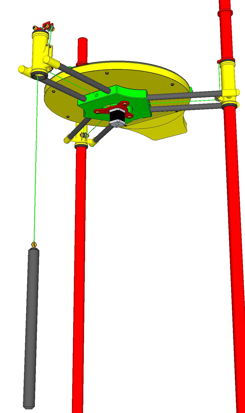
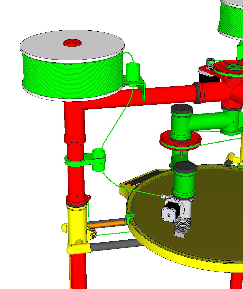
This is an illustration of the Z axis mechanism with a counterweight incorporated to offset the bed slider assembly. The slider itself will remain somewhat heavier than the counterweight so that gravity loading of the slider will maintain position controlled by the stepper string reel centered under the bed.
|
Re: Delta Scara - 3D printer design June 26, 2014 10:37PM |
Registered: 10 years ago Posts: 1,381 |
Looks cool 
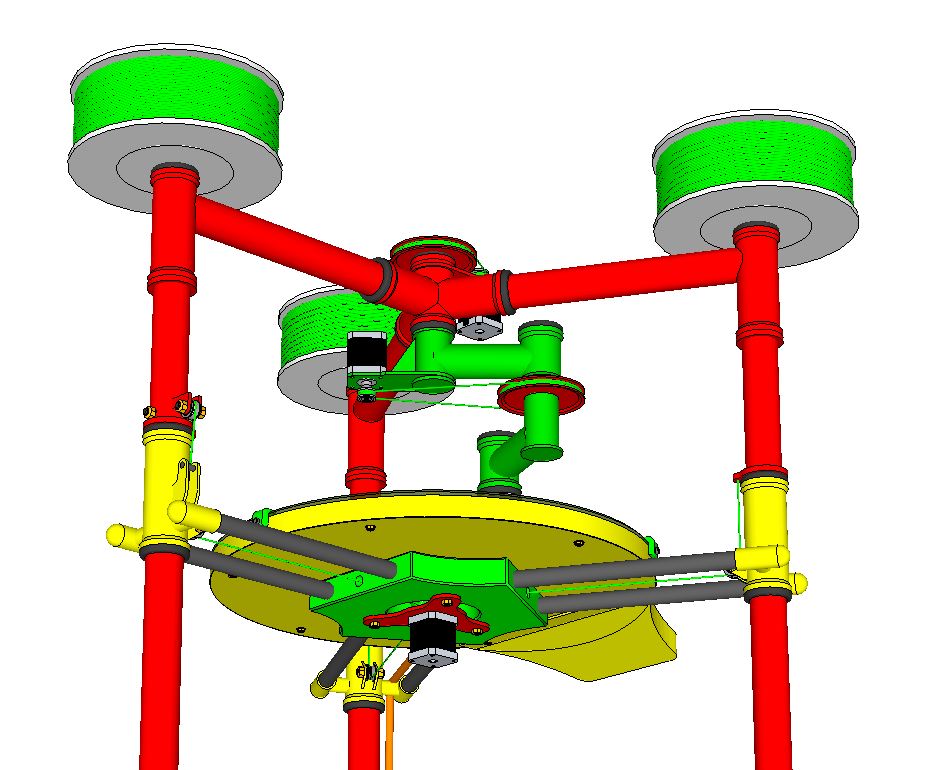
I agree with see3d, you can move the elbow motor, and pulley on top of the upper arm, that will allow you to keep your upper arm bracket. You could even move the elbow motor behind the shoulder pivot, the belt would pass on either side of the column. Not sure about the ratio change doing it that way, but you would eliminate nearly all the weight off of the upper arm, less the pulley. I would also spread out the bearings above, and below the elbow as much as possible.
I think the base needs to be triangulated, or a solid plate be used. The vertical columns are going to twist, and that could bind up the Z-axis.
The supports coming off the column to the build plate I think can be eliminated with a single sheet. I see lots of work putting it together, so reduce your part count if you can.
I'm not sure if you have your filament on top of the machine, but best to keep the mass as low as possible, the frame will shake it's self apart if it's top heavy.
|
Re: Delta Scara - 3D printer design June 26, 2014 11:14PM |
Registered: 10 years ago Posts: 169 |
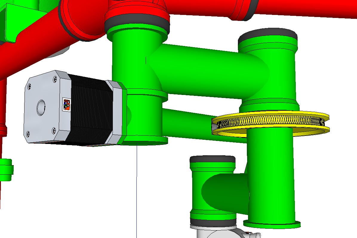
Thanks A2. I think you mean something like this for the elbow motor/pulley and lengthen the elbow neck tube to separate the bearings.
I think the bed slider needs the stiff CF tubes for strength, weight savings and cost of the build. They're really not very expensive in relation to what a big plate of aluminum would cost for material and fabrication. They would all be epoxied in place so the strength of the assembly would be there. Welding up the fittings on the sliders for the CF tube mounts isn't really that much of a deal once a production jig is built. The biggest and heaviest piece for the bed would be the 18" dia. piece of beveled glass. I had considered ceramic but I think that might be heavier still. I can slip another set of the aluminum arms down to the base to stiffen that area up. Welding the base pieces together would be better but I want to be able to break it all down to manageable crating size.
Thanks...TP
|
Re: Delta Scara - 3D printer design June 27, 2014 01:56AM |
Registered: 10 years ago Posts: 1,381 |
That looks good.
You could also off set the elbow stepper motor, which would eliminate the pulley encompassing the column, and have a direct shot to the elbow pulley. Or rotate the motor 90 deg around the tube to eliminate the pulley.
I don't think (?) you need the counter weight, as the build plate is only moving down. I would think that you would want a heavy build plate, less I'm not seeing the bigger picture.
|
Re: Delta Scara - 3D printer design June 27, 2014 04:15AM |
Registered: 10 years ago Posts: 169 |
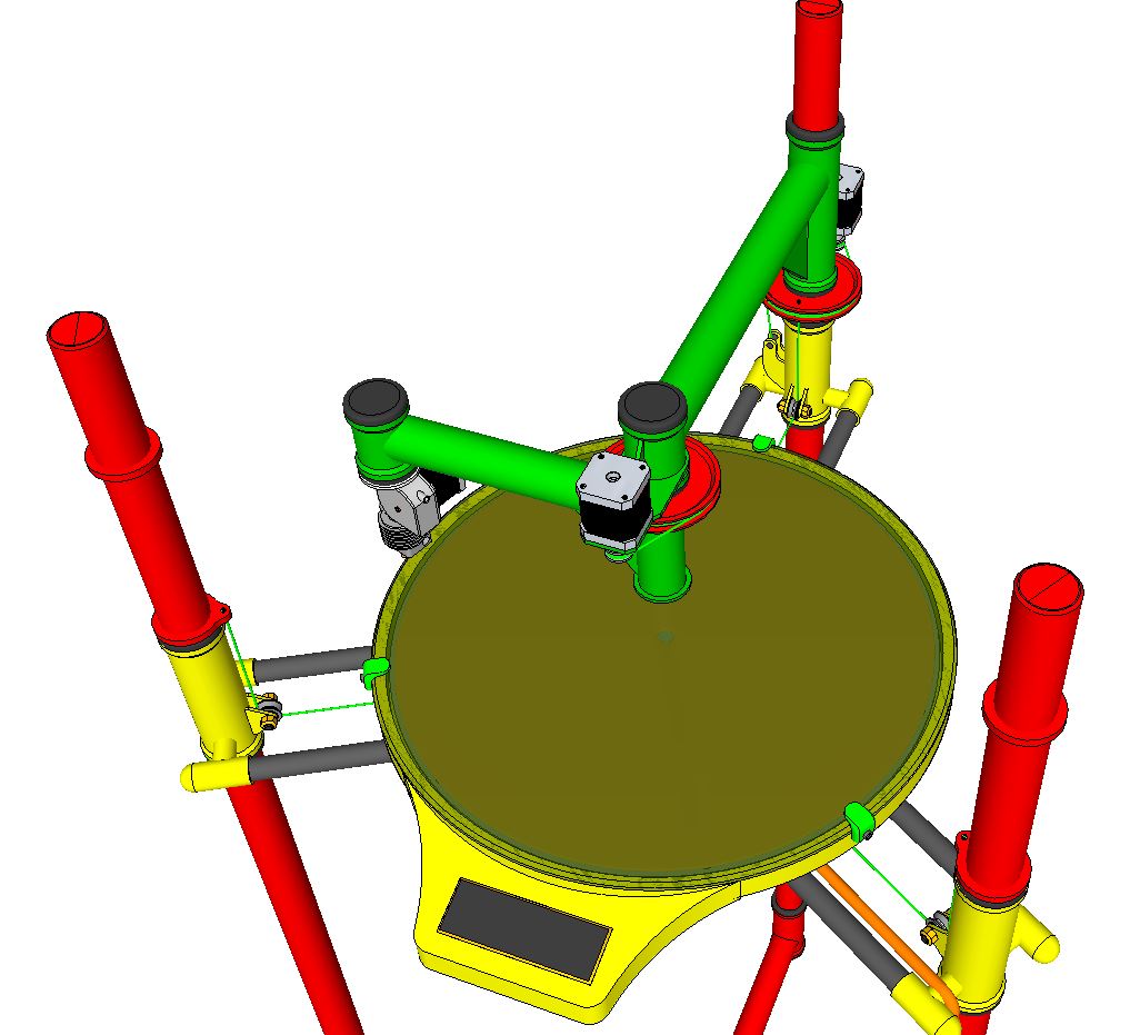
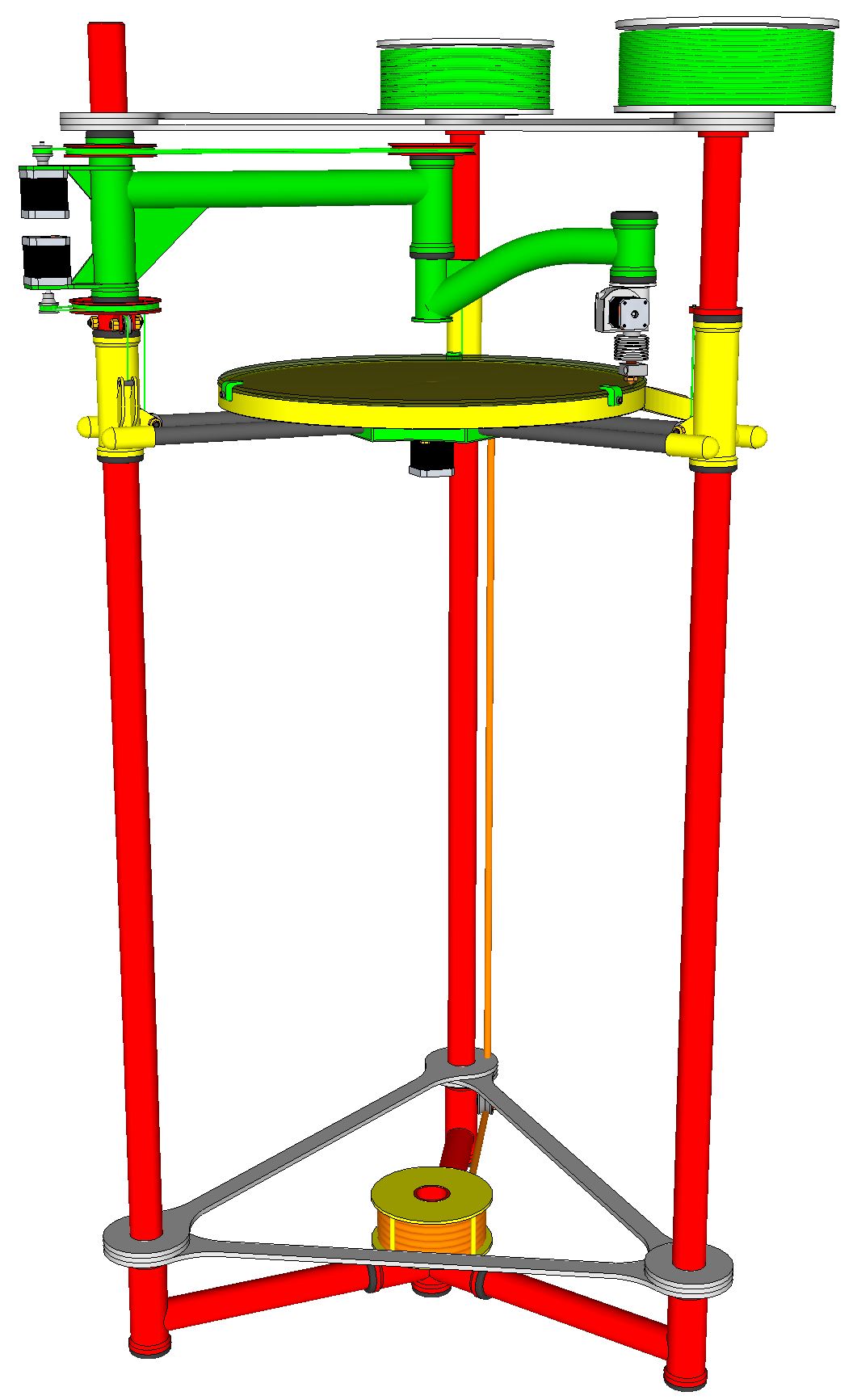
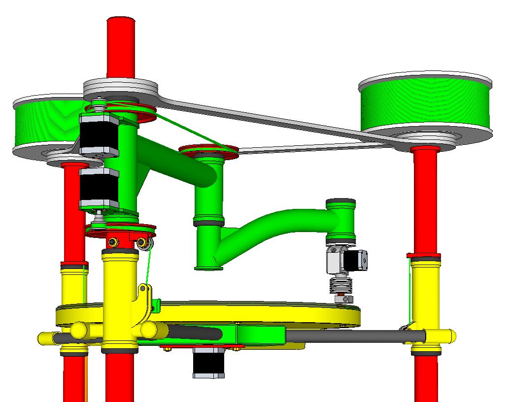
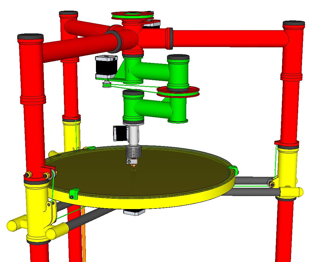
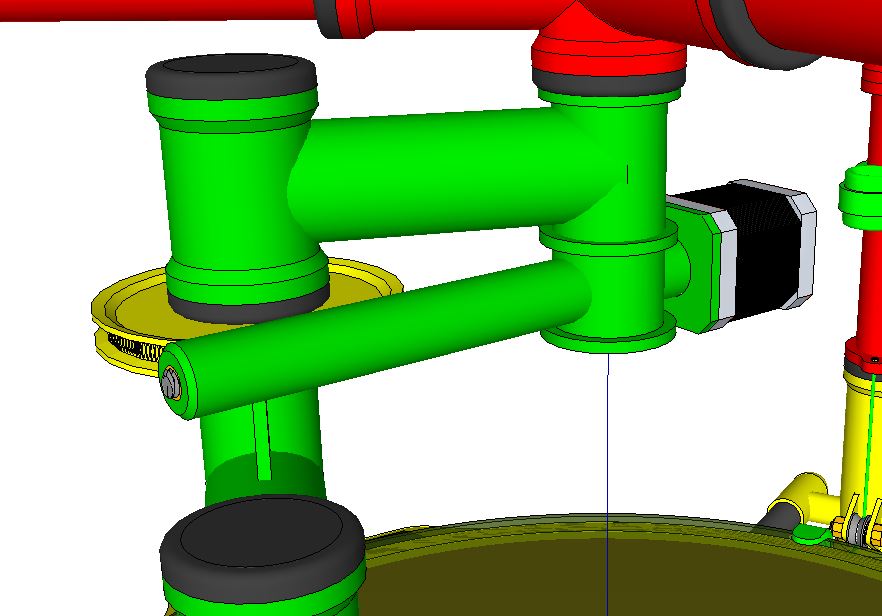
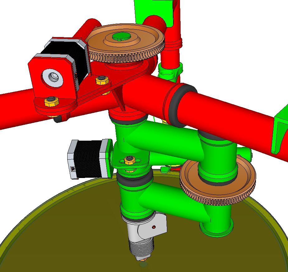
Yes...right again on the motor location A2. However I've just changed the arms up to follow a suggestion Nicholas made to an email question I had posed to him earlier. These drawings show the new arm center mount that reduces the weight and mechanical force on the frame and steppers. The added tube supports also helps to brace the top of the frame. Nicholas also said the drive ratios should be about 1:50 depending on the length of the arm. As drawn I'm showing 1:5.4 comparing the circumferences of the two pulleys. Am I calculating that wrong?
On the counterweight there are a couple of things I'm considering. One, the static load on the single stepper's rated torque which is holding up the entire weight of the slide and bed. The counterweight virtually negates that load. Also, when a second hot end is added the bed can be set to drop and raise between color changes so not to leave color residue from one head to the other.
Second, when the power to the stepper cuts, the slider assembly would fall like a rock to the bottom without the counterweight. Approaching balance the bed should just ease down more gently shouldn't it. I know a rock and a feather fall at the same rate but would that apply here with the spool windings in play? Any suggestions how to catch the bed when the power cuts or is switched off?
Edited 1 time(s). Last edit at 06/27/2014 04:17AM by simspeed.
|
Re: Delta Scara - 3D printer design June 27, 2014 11:23AM |
Registered: 10 years ago Posts: 100 |
Take care about the path the filament will take in getting to the hot end. It looks like it could get all hung up on the structure and arms.
Catching the table if it falls is not so hard. Just have a spring at the bottom to decelerate it. You can also have a can with a close fitting plunger to use as an air shock damper. I did this on a machine to catch a fast 15 pound arm X motion that was moving quickly on a retract to home position. It worked good as long as it is positioned at the center of the mass.
Catching the table if it falls is not so hard. Just have a spring at the bottom to decelerate it. You can also have a can with a close fitting plunger to use as an air shock damper. I did this on a machine to catch a fast 15 pound arm X motion that was moving quickly on a retract to home position. It worked good as long as it is positioned at the center of the mass.
|
Re: Delta Scara - 3D printer design June 27, 2014 02:58PM |
Registered: 10 years ago Posts: 169 |
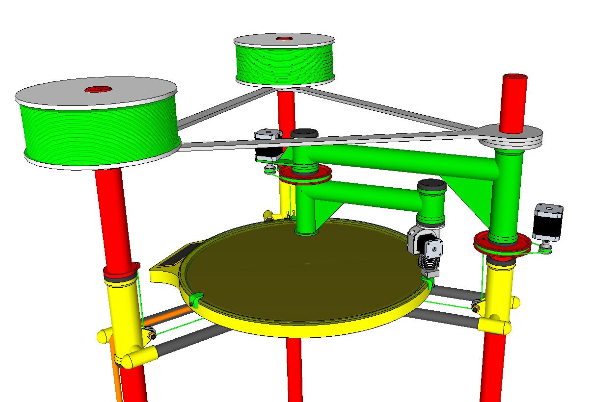
Yes indeed on the filament path. Something like what I've shown in this drawing should work. Especially since the hot end and extruder swivel on bearings at the arm end. The pull of the filament should always keep the extruder end pointed in the direction of the feeding spool if we leave enough play in the hot end power line connections. These printed plastic guides could be mounted below each of the three spools for a quick filament change when line runs out.
Good recommendation on an air shock damper for the bed slider. Have to think about how best to apply that or something like it without making the build more complicated. Maybe just a light compression spring resting on the top of the counterweight inside one of the vertical tubes. As the bed falls the counterweight would rise in the tube and the spring would compress at the top of the stroke to dampen the shock and let the bed settle on the bottom. The support line will have to be pretty strong to handle that shock wouldn't you think? Thanks....TP
Good recommendation on an air shock damper for the bed slider. Have to think about how best to apply that or something like it without making the build more complicated. Maybe just a light compression spring resting on the top of the counterweight inside one of the vertical tubes. As the bed falls the counterweight would rise in the tube and the spring would compress at the top of the stroke to dampen the shock and let the bed settle on the bottom. The support line will have to be pretty strong to handle that shock wouldn't you think? Thanks....TP
|
Re: Delta Scara - 3D printer design June 27, 2014 05:53PM |
Registered: 10 years ago Posts: 100 |
Your filament must be a lot easier to bend than my filament. I have to run a gentle arc from the spool to straight down through the extruder. Perhaps a 2-3 inch bend radius for 1.75mm PLA would be ok if it went around a guide on a bearing. Without a guide, I would say 4-5 inch radius in free air is about what my filament wants to curve without too much strain. That is the only filament I currently have to measure. Your filament is going to also rotate as well as bend as the XY moves. Something to keep in mind. That is one advantage of the moving Y tables printer designs. The filament only moves along the X axis, so it almost appears to be in a fixed relationship to the extruder drive mechanism. With a Bowden arrangement, the extruder and filament are in a fixed relationship. It is just the hot end that sees the rotation in the filament, and it is essentially in a liquid floating bearing at the melt zone. Now that I finally have my first 3D printer, I am understanding more about some of the subtile tradeoffs in the different designs.
|
Re: Delta Scara - 3D printer design June 27, 2014 06:28PM |
Registered: 10 years ago Posts: 169 |
Well that's one place where you have the advantage on me see3d....I have yet to own a 3d printer and do not have your experience with such things. I expected the filament to physically behave much like the plastic line I use with my string trimmer. I did not realize print filament behaves differently. I guess I better order a spool to observe the properties before I commit to those aspects of the design.
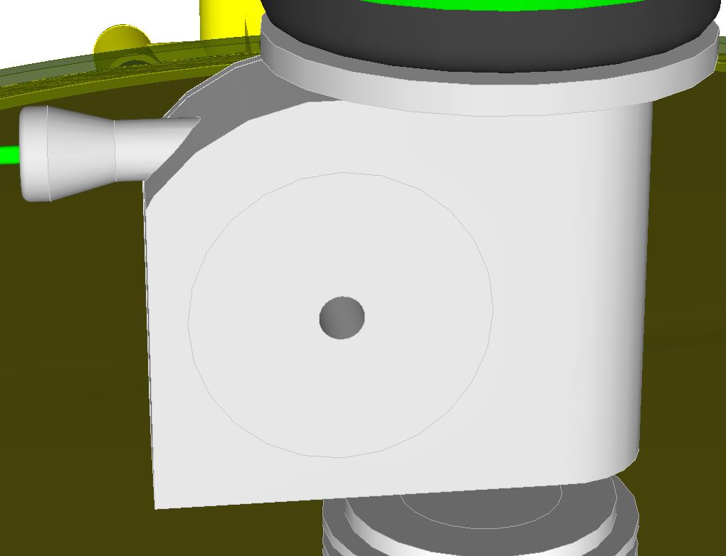
Not sure I understand your meaning about the filament rotating as well as bending. I don't see a rotating motion. As the extruder pulls the filament from the carriage spool, it will do so in a straight line as it pulls down through the guides and into the throat of the extruder. The extruder design I'm contemplating here uses a round milled channel that bends through a 90 degree radius from the inlet down into the hot end melt chamber. The hobbed spool that grabs the filament at the point where the 90 degree radius begins has a 1.3" diameter. It pulls the filament along the radius channel split between the spool and the housing. As the channel radius turns down where the rotating spool and the housing separate, the filament follows the channel opening through the housing down into the melt zone.
As you say it may be that the filament will not bend to that channeled radius without cracking/breaking. Is that what happens to your filament when you try to bend it to that degree? Thanks...TP
|
Re: Delta Scara - 3D printer design June 28, 2014 10:53AM |
Registered: 10 years ago Posts: 100 |
Rotating of the filament is less pronounced when you have arranged it like you did with the 90 degree bends. I was thinking of it if you came in from the top of the extruder and straight down.
Unless you have a rotational axis on the extruder, the line going to the filament will keep changing the angle of entry to the extruder. This is what happens instead of the rotation that occurs in the previous sentence.
When you move the head to the furthest point from the filament spool, then move the head to the closest point to the filament spool, the excess filament will bend in some wild way to take up the slack. It may just ben down into your partially built model and ruin it. The reason for having the filament come in from the top of the extruder is so there is a natural service loop. Coming in from the side, you will have to create a sideways service loop guide to take up the slack.
On my filament, a 1.3 inch diameter bend puts a permanent kink into it. It also has quite a bit of spring force to overcome. It does not want to bend that tight. Of course you can force it to do anything you want, but it is going against its yield point.
|
Re: Delta Scara - 3D printer design June 28, 2014 12:46PM |
Registered: 10 years ago Posts: 169 |
Yes, the extruder will rotate on it's vertical axis so the pull of the filament would always point straight back to the guide. I agree there will be a need to control line slack...have to think how best to work that out. Considering the side entry to the extruder, I better construct a prototype and test before committing to the larger design. All good points see3d...thanks. Very helpful to get other eyes and minds working to find the flaws. I do appreciate the help. Thanks...TP
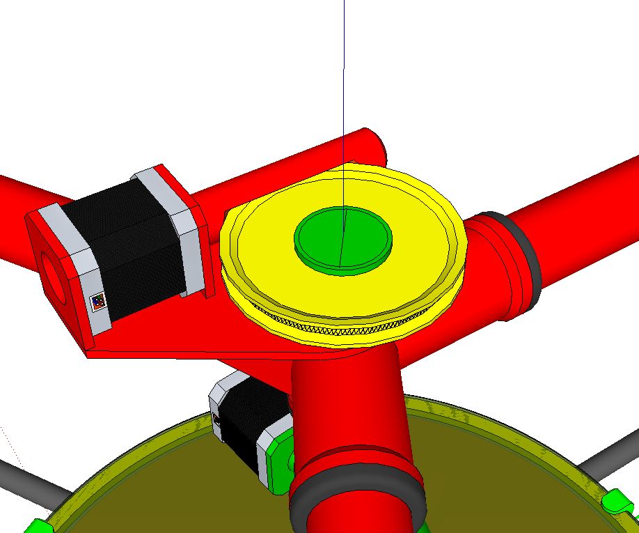
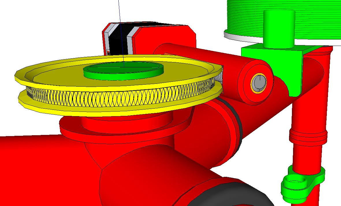
BTW... I've drawn up a worm drive design for the two arms based on work I saw from Solidus Labs. The pros are it allows for much smaller diameter pulleys to achieve the desired 1:50 gear ratio, it's compact and should be quite strong. I didn't draw in any adjustments but a pivot point about the center line and clamping nut should work to set preload of the worm against the wheel. The cons....I understand there are backlash issues to consider with any gear drive mechanism, but I think the worm can be position fixed at the end bearing so there is no movement along the linear axis. Something to consider....
BTW... I've drawn up a worm drive design for the two arms based on work I saw from Solidus Labs. The pros are it allows for much smaller diameter pulleys to achieve the desired 1:50 gear ratio, it's compact and should be quite strong. I didn't draw in any adjustments but a pivot point about the center line and clamping nut should work to set preload of the worm against the wheel. The cons....I understand there are backlash issues to consider with any gear drive mechanism, but I think the worm can be position fixed at the end bearing so there is no movement along the linear axis. Something to consider....
|
Re: Delta Scara - 3D printer design June 28, 2014 06:17PM |
Registered: 10 years ago Posts: 100 |
|
Re: Delta Scara - 3D printer design June 28, 2014 07:26PM |
Registered: 10 years ago Posts: 169 |
Yea, that's the kind of pivot I had in mind. I've drawn this up using a plate clamp like we see on old style auto distributors. I like this application...I think the pulleys can be sized even smaller in diameter than shown depending on the final drive ratio.
|
Re: Delta Scara - 3D printer design March 17, 2017 11:00AM |
Registered: 7 years ago Posts: 29 |
Hi simspeed, if you still working this project. I believe this firmware suite for you [github.com]
|
Re: Delta Scara - 3D printer design March 20, 2017 04:58AM |
Registered: 11 years ago Posts: 364 |
|
Re: Delta Scara - 3D printer design March 20, 2017 05:31AM |
Registered: 7 years ago Posts: 29 |
Quote
ekaggrat
@wangsamax
What is the advantage of your firmware over the others?
my firmware is developed from repetier which is better for non cartesian than the others.
I add some special functions for robotic arm, for instance to rotate individual angle rather than just move x,y
It has single and paralel scara kinematics included, I believe it will be easier to add some new robot arm kinematics in development
I also made special function to calibrate the arm lengths, angles and steps per units to make perfect print result
|
Re: Delta Scara - 3D printer design March 20, 2017 06:28AM |
Registered: 11 years ago Posts: 364 |
|
Re: Delta Scara - 3D printer design March 20, 2017 07:51AM |
Registered: 7 years ago Posts: 29 |
I believe it can, if you know the kinematics and inverse kinematics formula.
simpson is near with delta, you can use delta as drive system first as testing.
I believe it will work moving x, y, z axis but not correct.
I don't know you have to just modify the configuration or you have to modify the delta kinematics formula.
simpson is near with delta, you can use delta as drive system first as testing.
I believe it will work moving x, y, z axis but not correct.
I don't know you have to just modify the configuration or you have to modify the delta kinematics formula.
Sorry, only registered users may post in this forum.