Peachy Printer ideas
Posted by koopa
|
Peachy Printer ideas September 30, 2013 07:33PM |
Registered: 10 years ago Posts: 1 |
Hey guys,
Like many of you, I was fascinated and enamoured with the $100 photo-setting resin printer made in a very Macgyver fashion on Kickstarter. In the spirit of collaborative work, I sent some ideas to the creator to further refine/innovate the design on low-budget, which he appreciated and told me to post here. Feel free to build/add/utilise anything here, chuck in an idea or two yourself, or let us know how to refine these ideas further:
1) Since you are already using the microphone input to sense the impedance change as drips go past, you could also run two wires up the sides of the printing flask, and use the reduction in impedance (as more salt water bridges the gap) to help work out water level. You could make it somewhat digital by only having some very small points up insulated wire be conductive, and you could increase the delineation of the points by having the wires far apart at the bottom, and close at the top.
2) It seems as though you sometimes need time to move the laser. I would take a leaf out of old-school camera technology, and have a rotating shutter. It basically could just be a spinning disk with a section (perhaps even a movable section) letting the laser through, and a small part to block it out. A $0.20 CCD could tell you if the laser was 'reflecting back' (ie not currently passing through to the fluid), and it could have a fixed high frequency sent through it (very easy to generate), so that it would only pass this high frequency through when illuminated (very easy to differentiate from the drip signal and/or water impedance.
3) To account for various issues in choosing a flask that is not perfectly rectilinear, you could allow a 'calibration routine' where effectively it prints out a 3D ruler, and you just put against an ordinary ruler and answer some questions about the X,Y,Z axis discrepancies . To save resin, you could even provide a Blender function where easy-to-file-off millimeter markings get added to certain straight axes, and then you can use even your first prototype to calibrate the machine (I've assumed that varying level-outputs are going to cause big size differences in the printed output).
|
Re: Peachy Printer ideas October 01, 2013 11:11PM |
Registered: 10 years ago Posts: 100 |
In the Delta Google group one poster wanted to vet an idea for a Delta printer that could print 36 x 36 x 72 inch high prints for school research. This is what I just posted:
I think if I were to take on a project of these dimensions, I would approach it from a completely different direction. This is supposed to be ground breaking research after all. First I would print sideways. I would want to use a process that went from uncured to cured state with minimal shrinkage. I might look at the Peachy printer approach and use a DLP type projector to expose a whole layer at a time to speed up the print process. No heat would be needed, though having the water bath a bit warm could make it print faster. It would take two 36 x 36 x 72 inch wide tanks for transferring the water back and forth. The issue will be getting enough energy through the projector without frying the DLP device. You would have to use more than one projector to do it. Two projectors would cover 36 x 36 each, but you probably want at least 8 projectors with 18 x 18 area for each one. The projectors would work best if they were to raise up as the print layer rose.
Another approach would be to use a long X axis carriage with a line of Lasers. If you had 36 Lasers, each one would only be responsible for one inch line of pixels. Increasing the number of Lasers is a 1:1 reduction in print time. A resin raft could be made in different sizes to frame the resin into just the area needed for the print.
|
Re: Peachy Printer ideas October 18, 2013 08:37PM |
Registered: 10 years ago Posts: 2 |
Turning the laser on and off with a minimum of cost.
There are many bands of audio in the speaker output that aren't useful for controlling the mirrors. They can be used for other control signals.
To turn the laser on and off, you could inject a low amplitude, high frequency signal; eg 18kHz, -20db into the output of both L & R outputs. This could be filtered out with a very simple notch filter on the line controlling the mirrors but chances are you wouldn't actually need to.
Using another pair of notch pass filters, you could detect with high speed and accuracy whether the signals were in or out of phase. The electronics to do this would be very simple. The binary output from this detector could be used to turn the laser on and off.
Turn the laser on and off with the existing interface, two lines of code and a dozen analog components in the printer.
|
Re: Peachy Printer ideas October 19, 2013 12:41AM |
Registered: 10 years ago Posts: 2 |
Actually, now that I think about it a bit more. All you really need is a "laser off" signal so while the laser is on, there'd be no chance of the laser control signal effecting the mirrors. You'd still need the laser off signal to be fairly specific though so that unexpected mirror movements don't weaken the laser.
Also, with a laser pulsing functionality, the scan path of the mirrors could be significantly simplified, to a rectangular scan pattern, just like a CRT TV. The efficiency of the system would be in the software targeting the build zone. Changing the mirror movement to two different periods of simple harmonic motion would also improve the accuracy of the plot and allow isolated areas to be exposed with much simpler "tool paths".
It's a fascinating project...
|
Re: Peachy Printer ideas October 22, 2013 03:11PM |
Registered: 10 years ago Posts: 14 |
I wanted to mention the mirrors and their odd warping of edges on a a straight line. The mirrors are a second surface type which will eat up about 10% of the laser power going in and another 10% coming out and even more at more severe angles. So, two mirrors eat up about 40 to 60% of the laser's power. They also have a ghosted reflection artifact because some of the light bounces off the surface. And, the laser changes angle when it enters the glass or plexi material, like a flashlight beam does when it enters water. The difference of densities between air and the glass cause this. Also, aiming the laser at the center of the mirror doesn't work well with the pivot point on the back side of the mirror. If the pivot is moved to the front and a first surface mirror is used, then all those complex trig problems go away.
I made a couple of pictures to show the difference between first and second surface mirrors
Edited 1 time(s). Last edit at 10/22/2013 04:55PM by Spelljammer.
I made a couple of pictures to show the difference between first and second surface mirrors


Edited 1 time(s). Last edit at 10/22/2013 04:55PM by Spelljammer.
|
Re: Peachy Printer ideas October 22, 2013 06:54PM |
Registered: 10 years ago Posts: 1 |
@Spelljammer
This is along the lines of what I was thinking for potential causes of the warping. I think the pivot point comment is particularly on the mark.
It's hard to tell without seeing the designs; but I think part of the problem is that the position of the center point is in the middle of the thread - not actually at the mirror (front or back). This would change the distance from the laser to the mirror (and mirror to mirror) based on how far it's rotated; changing where the laser hits on the next object in the chain.
I can't draw anything up at the moment; but a rough (albeit extreme) approximation would be putting a baseball card on a wheel.
|
Re: Peachy Printer ideas October 22, 2013 08:33PM |
Registered: 10 years ago Posts: 14 |
Good point, Paul. If you notice my second drawing, I placed the pivot point at the mirror surface. It would involve etching a notch in the surface as deep as half the diameter of the thread or fishing line so that the pivot is exactly at the mirror surface. This could be easily done when cutting the acrylic mirrors with a laser cutter. There is a way to use solvent to take off the back of an acrylic mirror so that the back side becomes a first surface mirror. I think with these changes and the ones Rylan has already done, this could be extremely accurate.
|
Re: Peachy Printer ideas October 22, 2013 08:43PM |
Registered: 10 years ago Posts: 2 |
These are very good points, both of which we were aware of. Rylan's early prototypes used a second surface mirror (he once used old CDs), but I believe he is using first surface mirror for the recent prototypes and will definitely be using that in the final version. As for the pivot point, it gets a bit tricky. To make this simple to build as a kit, we are currently using a tensioned thread as the pivot for the mirrors. Keep in mind, this is something we are actively iterating on, so that may not be the final design, but it's simple and works fairly well right now. The problem is that we need a continuous piece of thread in order to easily attach it, so it's on the back of the mirror. I have considered building mounts for the ends of the mirror that would hold the center of the front face in the axis of rotation, but that would require a different way to mount the pivots for the mirrors. We'll see what options we can come up with that are cheap, easy to assemble, and have the physical properties that we desire. However, I have modeled the effects of this in Blender and it doesn't seem to cause a major problem. I can still draw a circle and a square without any unexpected warping.
As for the warping, I've actually narrowed it down to be caused by the orientation of the laser to the mirrors. Because the laser isn't orthogonal to the first mirror, the rotation of the mirror actually causes the light to follow an arc rather than a straight path. It's hard to describe it in words. Imagine a ray of light leaving the mirror at a shallow angle from the axis. When you turn the mirror, the start of the ray stays on the axis, but the direction of the ray rotates around the axis of rotation of the mirror. When it strikes the second mirror, it doesn't always land on the axis of the mirror. This is easily fixed by making the mirrors and laser all orthogonal, as is done in commercial 2D laser scanners. When everything is orthogonal, the light still follows a curve, but the curve runs along this axis, so it doesn't affect the apparent angle of the second mirror. Again, it's easier to draw than to explain, but hopefully that helps to understand. There is still the ever-present problem that we are controlling the angle, but drawing against a flat surface (a spherical projection on a Cartesian space), but that's easily accounted for with trig.
As for the warping, I've actually narrowed it down to be caused by the orientation of the laser to the mirrors. Because the laser isn't orthogonal to the first mirror, the rotation of the mirror actually causes the light to follow an arc rather than a straight path. It's hard to describe it in words. Imagine a ray of light leaving the mirror at a shallow angle from the axis. When you turn the mirror, the start of the ray stays on the axis, but the direction of the ray rotates around the axis of rotation of the mirror. When it strikes the second mirror, it doesn't always land on the axis of the mirror. This is easily fixed by making the mirrors and laser all orthogonal, as is done in commercial 2D laser scanners. When everything is orthogonal, the light still follows a curve, but the curve runs along this axis, so it doesn't affect the apparent angle of the second mirror. Again, it's easier to draw than to explain, but hopefully that helps to understand. There is still the ever-present problem that we are controlling the angle, but drawing against a flat surface (a spherical projection on a Cartesian space), but that's easily accounted for with trig.
|
Re: Peachy Printer ideas October 22, 2013 09:08PM |
Registered: 10 years ago Posts: 14 |
Thanks for the quick reply, James.
I had a quick thought on mounting the thread to the front surface. If there are laser etched notches (small one at the top and bottom) on the first surface side of the mirror, the assembler could stretch the thread across the mirror surface with the thread in the notch at each end. Apply glue at those two spots and when it dries, use a knife or razor to cut the thread's middle out just above and below the spots of glue. This way, the thread is just at the top and bottom edges. The mirror might have to be slightly longer to accommodate.
Also, I wanted to point out that even a first surface mirror using a rear pivot point will make it so the laser is not always at the center line. It changes where the laser hits based on angle of rotation. Reference my first picture and pretend it is a first surface. The only way to fix that is to have the pivot point at the first surface mirror.
|
Re: Peachy Printer ideas October 23, 2013 02:07AM |
Registered: 14 years ago Posts: 14 |
|
Re: Peachy Printer ideas October 23, 2013 02:14AM |
Registered: 14 years ago Posts: 14 |
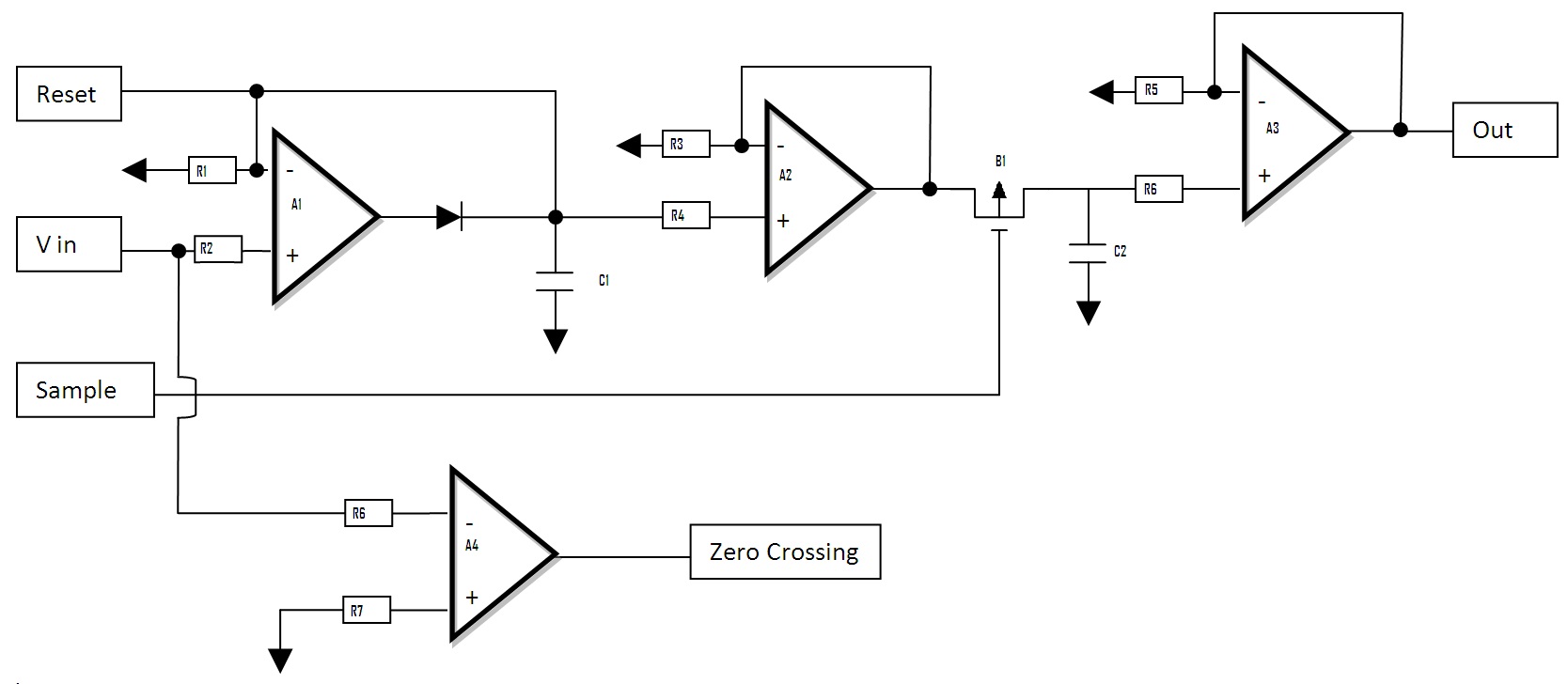
This might be a way to make small quick mirror adjustments for both X and Y using audio.
Two of the circuits below can be attached to a very cheap (35 cents) microcontroller to allow up to a 20 Khz amplitude modulated sound wave to generate 20,000 X,Y points for laser mirrors at sound card resolution. Any Micro controller (I use Microchip) with at least 5 I/O pins and any Op amp rated at 60Khz rail to rail, 5Volts. Caps can be ~.01 mf and resistors ~10K. Because the values have to be held for a very short time there are no critical components.
Here is a brief description of the process:
Reset – I/O from Micro, Sample- Output from Micro, Zero Crossing- Input to Micro
Vin- Input from sound card, Out- Output To Mirror
Given: Amplitude modulated 20Khz sine wave Peek equal the Position (X or Y) Centered at 0V.
2 Each of the circuits below (One for X One for Y Mirrors)
When Zero Crossing goes HIGH (+ to – Zero crossing) Set Sample HIGH for a 10 micro second pulse
This takes the last Sample.
then Set Reset as Output LOW for 10 micro seconds
Resetting (Discharging) the peak detector Capacitor.
then Set Reset as input.
Out will be the peak of the last AC cycle until the next Zero Crossing
Edited 1 time(s). Last edit at 10/23/2013 06:54PM by tag16c.
|
Re: Peachy Printer ideas October 23, 2013 07:18PM |
Registered: 14 years ago Posts: 14 |
A simple clip on the back of the mirror (Made by the printer) on the string could be used to "PUSH" the string to the front face of the mirror to effect a front surface pivot point.
This way the string is continous and glued to the rear of the mirror but in the Front Surface Plane for rotation.
This way the string is continous and glued to the rear of the mirror but in the Front Surface Plane for rotation.
|
Re: Peachy Printer ideas October 24, 2013 01:52AM |
Registered: 10 years ago Posts: 2 |
Thanks Spelljammer and tag16c. Those are both great ideas for getting the thread to the front face of the mirror and both simple and cheap. I like them!
tag16c, thanks for the suggestion on the circuit. I'll keep it in mind. Right now we don't need to worry about that; we are nowhere needing those high of speeds. The circuit Scott is working on now is a simple capacitor-and-diode edge detector for doing demodulation of the amplitude modulated signal (for those AC-coupled sound cards). Since we are slowly panning our mirrors around, rather than continuously cycling the same image and over again (as would be needed for persistence of vision in a laser light show), we don't need to move nearly that fast. If we do get our mirrors moving that fast, perhaps we will have to look into something like that, but I suspect we'll first need to provide closed loop control of the galvos to get those speeds.
tag16c, thanks for the suggestion on the circuit. I'll keep it in mind. Right now we don't need to worry about that; we are nowhere needing those high of speeds. The circuit Scott is working on now is a simple capacitor-and-diode edge detector for doing demodulation of the amplitude modulated signal (for those AC-coupled sound cards). Since we are slowly panning our mirrors around, rather than continuously cycling the same image and over again (as would be needed for persistence of vision in a laser light show), we don't need to move nearly that fast. If we do get our mirrors moving that fast, perhaps we will have to look into something like that, but I suspect we'll first need to provide closed loop control of the galvos to get those speeds.
|
Re: Peachy Printer ideas October 27, 2013 03:07PM |
Registered: 10 years ago Posts: 3 |
Hi to everybody,
a idea of another concept to build a low cost galvo. In this way i use only one mirror and the problem of the axis of the Pivot-point.is solved.
I hope this works, i have ordered a laser and a first surface-mirror and when it arrieved i try to build and test it.
.... any bugs in my thoughts ???? ... let me know !!! ...
The red pieces are the coils, the orange are the magnets
|
Re: Peachy Printer ideas October 28, 2013 06:05PM |
Registered: 10 years ago Posts: 14 |
I too have been working on a single mirror design. This is just a mirror held balanced on a center fulcrum by 4 small rubber bands. There are 4 coils and 4 magnets. Each opposite coil and magnet work together. For instance, to move left, the X coil 1 and coil 2 energize, the magnets under each is set to the opposite polarity, the right one could be North pointing up and the left one pointing down. So, one coil pushes and the other pulls for one direction, and the opposite for the other direction. I could have used just 2 coils, but I thought it would be more balanced with 4. I'll have to make a prototype.


|
Re: Peachy Printer ideas October 28, 2013 07:24PM |
Registered: 14 years ago Posts: 14 |
Your design is simple and looks great! Wish I had thought of it. .
.
Maby springs instead of rubber bands.
Have you done the math on compensating for the fulcrum on the rear of the mirror instead of the front, (mirror thickness,distance, at the reflected angle) it should not be too hard to do?
Edited 1 time(s). Last edit at 10/28/2013 07:26PM by tag16c.
. Maby springs instead of rubber bands.
Have you done the math on compensating for the fulcrum on the rear of the mirror instead of the front, (mirror thickness,distance, at the reflected angle) it should not be too hard to do?
Edited 1 time(s). Last edit at 10/28/2013 07:26PM by tag16c.
|
Re: Peachy Printer ideas October 29, 2013 02:32PM |
Registered: 10 years ago Posts: 3 |
@ Spelljammer Great idea ! Looks pretty cool. Is it possible to compensate that pivot-point problem only with software ?
Are you not afraid that if a coil is energized the magnet will be attracted and "snap" to the coil and that's it. Cause the magnet could reach the coil without
any obstruction? Or i'm totally wrong?
@ tag16c It's about your circuit .... i read your post over and over again. Surely i'm the only one in this forum who did'nt understand it very well.
Are you so kind to explain it with more easy words for me. Is it a circuit to move mirrors generally or to move mirrors much more faster than normaly?
I've read your brief description of the process ...can you explain it in a way you explain it to your grandpa or a non electric-engeneer
...cause i would like to understand it in general what this circuit is doing, not every tiny bit by bit, but general.
....and describe it in german language .... hahahahahaha , just kidding
thanks a lot ...
|
Re: Peachy Printer ideas October 29, 2013 03:13PM |
Registered: 10 years ago Posts: 1,381 |
@ Spelljammer
Are you depicting a voice coil servo, or something entirely different?
If you are, then maybe you don't need the rubber band, as you can control the position of the coil?
A speaker uses the foam ring around the speaker cone to center the coil and hold it in position, maybe some thing like that can be incorporated?
Two Axis Voice Coil Motor Stage
[www.youtube.com]
Hard drive voice coil
[www.youtube.com]
A2
|
Re: Peachy Printer ideas October 29, 2013 06:15PM |
Registered: 14 years ago Posts: 14 |
Dino,
First moving faster allows movement without turning laser off ie 2 colums not connected.
More powerful laser would mean more complicated peice or faster print or finer laser resolution and squarer corners.
But this could cost upto $5.00 with driver amps for the coils instead of the .10 for a diode and cap.
The microcontroller of choice for me is the PIC 12F1501 cost about $0.75 8 pin dip.
My writing skills are not the best even in english (my native language) but I will take a shot at describing the circuit.
All of the op amp circuits are from generic stuff.
A1,C1 is a peak detector
A2 is a Voltage follower (Buffer)
A3 B1,C2 is a sample and hold Circuit.
A4 is a comparator comparing Vin to zero volts.
The sequence is:
Vin is an amplitude modulated signal that can change amplitude from one cycle to the next.
As Vin peaks high C1 is charged to that maximum voltage using A1. The diode keeps C1 from discharging.
A2 is a buffer/voltage follower to keep C1 from discharging when the voltage is passed to C2 (below).
When Vin crosses zero volts A4 compares Vin to zero volts and turns Zero Crossing High.
The computer sees this high and sends a signal to Sample. Sample high turns B1 (the analog switch, Mosfet ) on and the voltage at the output of A2 is passed to the sample and hold circuit A3.
C2 is charged/discharged to the new voltage of C1.
After Sample is turned back off C2 will not follow C1. Then the computer makes Reset a low output and discharges C1.
Reset is then made an input again high impedance and C1 is allowed to follow Vin again.
This Sample and reset all happens while the sign wave is in the negative cycle.
Summary
Vin is an amplitude modulated signal. The circuit monitors the AC sine wave and picks the top of each sine wave and puts it out at the output of A3.
You may need a driver on the output of A3 for the coil if the op amp (A3) cannot supply enough current to the coils.
The circuit I have described is for either X or Y you need two to drive the Printer.
Maby the attached picture will help.
If you have specific questions about the parts I will see if I can explain.
Tag16c
Edited 4 time(s). Last edit at 10/29/2013 10:03PM by tag16c.
|
Re: Peachy Printer ideas October 29, 2013 06:15PM |
Registered: 10 years ago Posts: 14 |
@tag, thanks. Springs would be better. But I was envisioning something I already had. My wife has this flexible strands that are for beading, but it looks like fishing line but it is very rubbery. As far as the math, I haven't even thought about it. It would be good to know, so if you feel like tackling that  But, even with that, I think the movement wont be linear towards the extremes and the software would still have to compensate.
@Dino, As one coil moves close to a magnet, the opposite side lifts away from its magnet and the only force opposing that motion will be the opposite sides rubber band or spring.
@A2, It is a little different just because the one mirror has already been integrated into the x and y movements. Try to imagine attaching a single mirror to the device in the first video you posted. (That is a cool looking device, by the way.) But you are right, I could get rid of the bands and replace with some foam or other flexible edging around the mirror. It might be tricky for a diy at home, but mass produced, I think your idea definitely has merit. Like use a round mirror with foam edging like a woofer
As another idea....since these laser modules are so lightweight, what if there were no mirror, but instead the pivoting platform had the laser module mounted on its surface? Not sure how well it would work, just thinking out loud.
But, even with that, I think the movement wont be linear towards the extremes and the software would still have to compensate.@Dino, As one coil moves close to a magnet, the opposite side lifts away from its magnet and the only force opposing that motion will be the opposite sides rubber band or spring.
@A2, It is a little different just because the one mirror has already been integrated into the x and y movements. Try to imagine attaching a single mirror to the device in the first video you posted. (That is a cool looking device, by the way.) But you are right, I could get rid of the bands and replace with some foam or other flexible edging around the mirror. It might be tricky for a diy at home, but mass produced, I think your idea definitely has merit. Like use a round mirror with foam edging like a woofer
As another idea....since these laser modules are so lightweight, what if there were no mirror, but instead the pivoting platform had the laser module mounted on its surface? Not sure how well it would work, just thinking out loud.
|
Re: Peachy Printer ideas October 29, 2013 09:51PM |
Registered: 14 years ago Posts: 14 |
|
Re: Peachy Printer ideas October 30, 2013 01:42AM |
Registered: 10 years ago Posts: 1,381 |
I was thinking of alternative ideas to control the mirror,
and the idea of a spherical motor came to mind
Then I found this video:
Spherical Induction Motor (tentative)
[www.youtube.com]
BallIP-PSR / new Ball Drive using Partially Sliding Roller / IROS2010
[www.youtube.com]
experiment of spherical motor.mpg
[www.youtube.com]
experiment of spherical motor
[www.youtube.com]
Same person controlling a laser with a gyro:
Gyroscope
[www.youtube.com]
@ tag16c
Latex/TPE/TPU potentially could work, but I don't like the idea of using a mat'l that degrades over time.
There is also a strange property of elastomers to become hot when expanded, and cold on contraction.
Hold a rubber band to your lips to experience this phenomenon.
So I'm not sure if that would effect the system, probably OK to use.
Edited 2 time(s). Last edit at 10/30/2013 04:56AM by A2.
|
Re: Peachy Printer ideas October 30, 2013 08:32AM |
Registered: 15 years ago Posts: 376 |
I don't know whether this is possible, but you could produce a continuously rotating device and switch the laser on / off. It works for laser signwriters (You see these at concerts writing across dry ice smoke ) Perhaps just doing this to replace one mirror may make the mechanical hardware much simpler. After all electronic circuits / software are generally much cheaper than hardware.
Could you use a liquid crystal shutter or rotating slotted disk.
Would it be possible to control the laser pulses via the audio track perhaps using a high frequency pulse off the audio range of the other axes.
Helium Frog Website
Could you use a liquid crystal shutter or rotating slotted disk.
Would it be possible to control the laser pulses via the audio track perhaps using a high frequency pulse off the audio range of the other axes.
Helium Frog Website
|
Re: Peachy Printer ideas November 01, 2013 09:15AM |
Registered: 10 years ago Posts: 3 |
@tag16c
thanks a lot !!! I have understand your circuit .You can move the mirrors 20,000 times per second ( if the galvos/hardware can handle it) thats right?
And JamesCooper and the peachy team are do'nt working with 20kHz audio out, instead they are using a lower frequency sine wave and handle the amplitude peak with cap and diode. thats right ? For the printer they don't need that fast mirrors, for now. They are charging the peak voltage from the amplitude into the cap and lead it to the coil of the mirror, then discharging the cap, charging the next peak of the amplitude and so on, thats right ??? ( it's saying with easy words)
@ JamesCooper
you convert the 3d Modell into g-code and the g-code into audio signals. what max. frequence you use for the audio?
BTW: when it was planed to make the code of the peachy public? After the rewards for the backers are delieverd ? Or when the beta-tester received his peachy?
thanks a lot !!! I have understand your circuit .
You can move the mirrors 20,000 times per second ( if the galvos/hardware can handle it) thats right?And JamesCooper and the peachy team are do'nt working with 20kHz audio out, instead they are using a lower frequency sine wave and handle the amplitude peak with cap and diode. thats right ? For the printer they don't need that fast mirrors, for now. They are charging the peak voltage from the amplitude into the cap and lead it to the coil of the mirror, then discharging the cap, charging the next peak of the amplitude and so on, thats right ??? ( it's saying with easy words)
@ JamesCooper
you convert the 3d Modell into g-code and the g-code into audio signals. what max. frequence you use for the audio?
BTW: when it was planed to make the code of the peachy public? After the rewards for the backers are delieverd ? Or when the beta-tester received his peachy?
|
Re: Peachy Printer ideas November 06, 2013 10:05PM |
Registered: 10 years ago Posts: 2 |
I've been working on a single mirror galvanometer design also. I just put my design up on thingiverse and I figured I'd share with you guys. http://www.thingiverse.com/thing:179041. It's a work in progress but I'm making pretty good headway on it. I've ditched driving it straight from a headphone jack, if I'm going to build a printer based on this method i'd rather have it dedicated to a microcontroller. Right now I'm using an arduino and 4 FDS8858 to drive the coils.
Tim
Tim

|
Re: Peachy Printer ideas November 09, 2013 01:43AM |
Registered: 14 years ago Posts: 14 |
|
Re: Peachy Printer ideas November 09, 2013 02:49AM |
Registered: 10 years ago Posts: 14 |
I love the design. You could try to make the thin flexible supports S shaped or some zigzag shape to add more length in a short distance to make them more flexible. You could also leave the supports off and use fishing line glued in place. Or you could use that flexible line for beading that looks like fishing line but is stretchable.
I had an idea about returning to zero position. Any spring used will have some memory and the return to 0,0 will not be perfect. You could use the Arduino program to swing back past the neutral position and then return to neutral. How far you swing back could be based on how far and long you were at the other extreme.
Anyway, looks fantastic.
Edited 1 time(s). Last edit at 11/09/2013 03:02AM by Spelljammer.
|
Re: Peachy Printer ideas November 09, 2013 03:53AM |
Registered: 10 years ago Posts: 14 |

|
Re: Peachy Printer ideas November 11, 2013 07:58AM |
Registered: 14 years ago Posts: 14 |
Has any body tried to use a small brushless dc motor as a galvanometer?
I took apart a DC brushed motor last night and removed the brushes, I connected + voltage to one of the three windings, used the 2nd one as common and the third to a PWM output and the motor acted like a galvanometer.
My wires were too big so it did not move linearly but I will try again with a small brushless as soon as I can find one.
I know there is some problem with this but for the life of I can not see what it is.
|
Re: Peachy Printer ideas November 12, 2013 07:53AM |
Registered: 10 years ago Posts: 2 |
@tag16c
my driver is just a full bridge that driving with a PWM. I'm using 4 FDS8858 (half bridge drivers) to create 2 full bridges. Each of the FDS8858 has a 2n7000 that allows the gate voltage on the FDS8858 to swing up to whatever the V+ is that I drive the coils with. Right now I'm driving them with 6V.
@Spelljammer
I experimented with making the hinges more flexible. I tried lengthening the hinge and also thinning the hinge. in both cases it ended up making the mirror more susceptible to vibration. Moving the mirror too fast would cause a lot of ringing and so would any vibrations in the room. Also the thinner hinge was too frail and I broke it before too long.
i haven't tried the S shape or zigzag. I'm concerned that will allow for off-axis movement. you could have z axis movement from the magnet being sucked closer to the electromagnet. also, doesn't offer tension on the opposite axis - for example the Y magnet could deflect some from the X axis actuating
my driver is just a full bridge that driving with a PWM. I'm using 4 FDS8858 (half bridge drivers) to create 2 full bridges. Each of the FDS8858 has a 2n7000 that allows the gate voltage on the FDS8858 to swing up to whatever the V+ is that I drive the coils with. Right now I'm driving them with 6V.


@Spelljammer
I experimented with making the hinges more flexible. I tried lengthening the hinge and also thinning the hinge. in both cases it ended up making the mirror more susceptible to vibration. Moving the mirror too fast would cause a lot of ringing and so would any vibrations in the room. Also the thinner hinge was too frail and I broke it before too long.
i haven't tried the S shape or zigzag. I'm concerned that will allow for off-axis movement. you could have z axis movement from the magnet being sucked closer to the electromagnet. also, doesn't offer tension on the opposite axis - for example the Y magnet could deflect some from the X axis actuating

Sorry, only registered users may post in this forum.