Tri-Polar Bot Concept -- Meet Wally
Posted by see3d
|
Re: Tri-Polar Bot Concept -- Meet Wally July 02, 2013 09:49PM |
Registered: 10 years ago Posts: 100 |
I am thinking longer term when I talk about an ARM chip -- not an initial prototype. The electronics will have to come down in cost to make a really low cost Wally. So some of the comments I make are with that in mind -- just to not design things into a corner that rules out better future stuff without starting over from scratch.
The DLCJ is AWESOME! No question about it.
I would like to see the DLCJ version succeed first, because I like simple. I only bring up the other version because there are tradeoffs and it is good to have a fallback position if the tradeoffs push the design in that direction.
The DLCJ is AWESOME! No question about it.
I would like to see the DLCJ version succeed first, because I like simple. I only bring up the other version because there are tradeoffs and it is good to have a fallback position if the tradeoffs push the design in that direction.
|
Re: Tri-Polar Bot Concept -- Meet Wally July 04, 2013 01:33AM |
Registered: 10 years ago Posts: 979 |
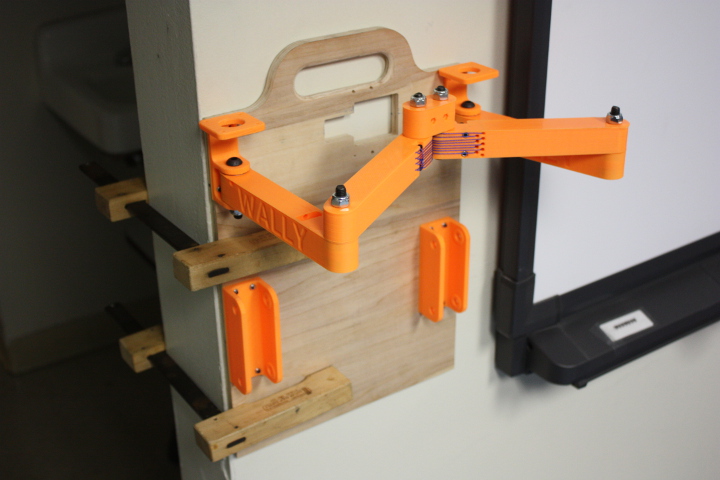
BIG UPDATE! I won't write much here and let the pictures and the video do the talking.
YOUTUBE RUNDOWN
I use to teach in Bentonville, AR. They had a small metal mill that I quickly feel in love with. When I married my wife and decided to move so we both didn't have to drive, I negotiated for the funds to build a mill. It is all my design. It is kind of like a RepRap for milling. It is made out of MDF pieces that it can mill itself. I built this 2'x2'x1' envelope mill for <$1000. I used plastic igus bearings and cheap wear compensating lead nut. The rods are solid 1.5"x3'. This thing weighs around 600 lbs. Blah, blah, blah. I only mention this because when I was trying to build this, I got a lot of info from cnczone. I am just dumbfounded by how much collective knowledge there is out there and how willing people are to share it.
You can see on the mill bed the backboard and the bed for Wally.
Here are a large portion of the parts. This looks like something a kid can and will be able to put together.
In just a few short minutes, this is what Wally looked like.
I will be out of pocket for about 2 weeks. I will still be trolling the forums but you guys will have to be patient for the next update and I can assure you that the next update will be something special.
Cheers,
Nick
Edited 3 time(s). Last edit at 07/04/2013 01:36AM by nicholas.seward.
YOUTUBE RUNDOWN

I use to teach in Bentonville, AR. They had a small metal mill that I quickly feel in love with. When I married my wife and decided to move so we both didn't have to drive, I negotiated for the funds to build a mill. It is all my design. It is kind of like a RepRap for milling. It is made out of MDF pieces that it can mill itself. I built this 2'x2'x1' envelope mill for <$1000. I used plastic igus bearings and cheap wear compensating lead nut. The rods are solid 1.5"x3'. This thing weighs around 600 lbs. Blah, blah, blah. I only mention this because when I was trying to build this, I got a lot of info from cnczone. I am just dumbfounded by how much collective knowledge there is out there and how willing people are to share it.
You can see on the mill bed the backboard and the bed for Wally.

Here are a large portion of the parts. This looks like something a kid can and will be able to put together.

In just a few short minutes, this is what Wally looked like.
I will be out of pocket for about 2 weeks. I will still be trolling the forums but you guys will have to be patient for the next update and I can assure you that the next update will be something special.
Cheers,
Nick
Edited 3 time(s). Last edit at 07/04/2013 01:36AM by nicholas.seward.
|
Re: Tri-Polar Bot Concept -- Meet Wally July 04, 2013 04:44AM |
Admin Registered: 16 years ago Posts: 13,886 |
Hi Nicholas,
the head seems to have two passive joints that will add undefined skewing to the tool-tip position
Either you'll fix one side or you should redesign the toolhead ...
Viktor
--------
Aufruf zum Projekt "Müll-freie Meere" - [reprap.org] -- Deutsche Facebook-Gruppe - [www.facebook.com]
Call for the project "garbage-free seas" - [reprap.org]
|
Re: Tri-Polar Bot Concept -- Meet Wally July 04, 2013 05:02AM |
Registered: 10 years ago Posts: 979 |
Have you read the stuff about the DLCJ (Double lamina compliant joint). The positioning effect would be the same as if the ends had spur gears. http://www.youtube.com/watch?v=RLMNi368M6U
Am I missing anything?
When I physically hold each elbow at a particular angle on my prototype I get a constrained setup.
Please let me know if you missed something or I did. My blood pressure just went up at the possibility of this not working as well as I imagined.
Am I missing anything?
When I physically hold each elbow at a particular angle on my prototype I get a constrained setup.
Please let me know if you missed something or I did. My blood pressure just went up at the possibility of this not working as well as I imagined.
|
Re: Tri-Polar Bot Concept -- Meet Wally July 04, 2013 12:54PM |
Registered: 10 years ago Posts: 979 |
Quick question for the masses... How do you guys feel about physical stops instead of electrical ones? The down side is that a human has to push each dof to an extreme before you print. I would take 2 seconds and save me around $10 in the final price. Simpson uses this be he also is spring loaded to approach the physical stops so I just have to turn the motors off to home him.
I could provide screws for adjustment so instead of going into firmware to calibrate you can just turn a screw.
I could provide screws for adjustment so instead of going into firmware to calibrate you can just turn a screw.
|
Re: Tri-Polar Bot Concept -- Meet Wally July 04, 2013 01:20PM |
Registered: 11 years ago Posts: 248 |
|
Re: Tri-Polar Bot Concept -- Meet Wally July 04, 2013 01:56PM |
Admin Registered: 16 years ago Posts: 13,886 |
Hi Nicholas,
DLCJ's should to be OK with 'strictly defining' the positions in respect to the joints ... but could be, that you'll get some additional angular displacement with the second 'elbow'-joints, what adds more complexity to the triangulation
Viktor
--------
Aufruf zum Projekt "Müll-freie Meere" - [reprap.org] -- Deutsche Facebook-Gruppe - [www.facebook.com]
Call for the project "garbage-free seas" - [reprap.org]
|
Re: Tri-Polar Bot Concept -- Meet Wally July 04, 2013 02:02PM |
Registered: 10 years ago Posts: 979 |
|
Re: Tri-Polar Bot Concept -- Meet Wally July 04, 2013 04:19PM |
Registered: 10 years ago Posts: 100 |
Nicholas -- WOW! Great update. It is official, you have now moved beyond the functionality of my cardboard model... LOL
Cool milling machine. I am drooling!
Don't worry about the arms not working, my microforce calibrated fingers already determined from my cardboard model that it is deterministic. ;-)
I would like to see gussets on the motor and arm back bracket, just to make sure that the plastic will not creep under the constant load. If the bracket came down a little further, you could also gusset the bottom too. Not needed in a prototype, but it is free insurance in a final design.
I think your method to tension the DLCJ with a plastic piece should work. I wonder about trying to align the effector and then tension it. Will it shift it back out of alignment again? Might need to print an alignment fixture that holds the 3 pieces in alignment while it is being tightened up. Perhaps just holding them all flat against a table will be good enough.
That is a clever use of the button head hex screw as an alignment point for the motor pulley.
The print area outline looks like it would be better defined as a 212mm (8.5") circle (enclosing the 150mm square).
I am also concerned about the heat near the hot end affecting the Spectra line. It is not designed to perform in high temperatures. First thing that comes to mind is to use HVAC aluminum tape. Stick a bit of insulating material to the tape (any poor heat conducting flat material), and put one wrap around the arm tip. The aluminum will reflect the heat away and the bit of insulation will do its bit and keep the tape from sticking to the strings.
Another idea would be to put the heat shield around the hot end itself. The hot tip will be at least an inch below the strings. A small fan to cool the cold end will also blow the heat away from the strings. This may be good enough.
One Idea I saw in the delta group recently was a flexible air tube that went back from the hot end to a stationary mini-squirrel cage fan (like a Bowden tube). I liked that design because it did not add mass to the effector and pinpointed the air to where it was needed. I think it was being used in this instance to cool the extruded filament to reduce sag in overhangs.
Air Tube
Homing is something I keep thinking about. I understand the elegance of making a straight arm the zero. I was originally thinking that the zero position should be with the head against the backboard, since everything is referenced to it, but there is something I like about straight arms also. It could be a mechanical stop based on the big pulley. The pulley can have a ridge along the bottom that keeps it from rotating on the forearm. I guess we have 2 shoulders, 2 elbows, and 2 wrist joints in this design -- 2 upper arms, 2 forearms, but just one common hand. Another ridge could keep the upper arm from being able to go past straight. Grab the arms, pull them straight and power the motors on. Back off one step and call it zero. That sets the geometric alignment of the arms so that it will match the reverse kinematics. I think the Hall effect might be more accurate if it can sense some micro-step resolution. It might still be a good idea to have a positive engagement between the pulley and the arm as a safety limit.
I wonder if we could make use of a cheap Laser pointer along the backboard to both home and act as a safety switch? If the effector tries to crash into the backboard, it would break the red line and stop moving. I like that Idea. Small industrial Lasers designed for such applications are <$5 at Amazon. It would also need a photocell to pick up the signal. It would be failsafe if the Laser or pickup were out of alignment or broken.
It could even be done with a physical trip string and a detector/switch for a safety kill switch, but perhaps not as accurate for homing. Kind of interesting idea.
I keep thinking that these stepper motors might be strong enough to break something if they crashed into stuff. Perhaps I am being overly cautious?
Well, I wanted to give a lot of ideas to keep you busy for the next two weeks... LOL
Edited 1 time(s). Last edit at 07/04/2013 04:27PM by see3d.
|
Re: Tri-Polar Bot Concept -- Meet Wally July 04, 2013 04:46PM |
Registered: 10 years ago Posts: 979 |
"microforce calibrated fingers" :-)
That is what I used! They are surprisingly cheap and accurate.
I will think on the laser some more. It might come in handy for the ATC.
This machine shouldn't be able to hurt itself too much. However, I am rethinking the idea of 6 limit switches. 2 for each dof. This way assuming the firmware is working the machine is never going to crash. It is so cheap that I think I am honor bound to do it. This machine looks like it could be in everyones home so I am going to design for the lowest common denominator then.
I played around with some gussets but never found anything that I considered elegant. Maybe you can draw me some ideas up. The problem is that the arms and strings cut into anything that I want to put in. I do so over forcing with my "force calibrated fingers" and during normal operation we are more than good and it can easily survive being thrown around in a car trunk with other crap on it. That said. I think you are right that a production model needs them.
The way I will be tensioning the strings will cause the effector to skew. I can mirror one of the arms and solve all of this. If I get rid of the printed on washer and splurge on a metal one... I can just flip one of the arms over. Crazy I know. So what is more important... 1) fewer unique plastic parts --OR-- 2) fewer total parts
I think I will switch to a circular bed. [store.qu-bd.com]. That will widden Wally by 2 inches but maybe that will let me perfectly align the "z arm brackets" with the "xy arm motor brackets"
In closing...
1) Gussets will be added just need to figure out where
2) limit switches of some kind will be positioned at the extreme of each DOF
3) work in a circular bed.
Additionally, I have a challenge for anyone that is interested. Wally is promising to be very RepRapable but the backboard while great for prototyping is cutting into how much can be self-replicated. The challenge is to come up with a basic idea to provide a skeleton for Wally from parts that can be printed in a 150x150x100 volume. Extra points will be given if this skeleton can aid collapsing Wally for transport.
|
Re: Tri-Polar Bot Concept -- Meet Wally July 04, 2013 06:09PM |
Registered: 10 years ago Posts: 100 |
Here is a quick picture of one possible way to add gussets.
The ones under the motor go off at a 45 deg angle as in the section view to avoid the spool and the motor screws. If you wind the string in a figure 8 between the two pulleys, there will be no possibility of interference from the looks of it.
The other main gussets are under the arm by extending the bracket down further.
The gussets above the arms are tight, so might not get to the center with them.
I think it is more important to get a good reliable Wally design than make every possible part out of FDM. There are some parts that will never by printed by Wally, like bearings, motors, bolts. Something like a metal washer is a no brainer.
From the backboard point of view, you need one structural part that can serve as a reference for everything. Flat stock is much flatter than printed parts, and much cheaper too. I will be quite curious as to what someone could come up with that would work in its place. If you really want Wally to make more of another Wally, then perhaps you need to think about what other tool heads could be used to do more. Perhaps Wally can spot drill holes in a board?
|
Re: Tri-Polar Bot Concept -- Meet Wally July 04, 2013 06:27PM |
Registered: 10 years ago Posts: 979 |
Flat stock makes the most sense without a doubt. I would not go into production with a printed frame. I am thinking about it more as a mental exercise. Proto Wally will not change directions too much besides what I already mentioned.
Thanks for the drawings. I will see what I can do.
Side note: how is this going to work business wise when I go into production. I have put in a lot of mental capital but it is definetly a team effort?
Thanks for the drawings. I will see what I can do.
Side note: how is this going to work business wise when I go into production. I have put in a lot of mental capital but it is definetly a team effort?
|
Re: Tri-Polar Bot Concept -- Meet Wally July 04, 2013 09:31PM |
Registered: 10 years ago Posts: 100 |
"It is amazing what you can accomplish if you do not care who gets the credit." -- Harry S. Truman
If you go into production, I will be your biggest cheerleader.
Just don't start something like a Kickstarter before getting all the kinks out of the prototype first. Wally is conceptually a bit different than other bots, and there may be a few surprises hidden in there yet to be discovered. Too many KS campaigns start and are too successful in funding before the product or the creator is really ready. Then the pressure is on to deliver and keep way too many contributors informed and happy about the progress. Completing the design issues becomes 4x as hard under those conditions. Work with a dozen or so Beta Testers to help iron out any kinks first.
I have started a few small companies in my time (including a part time one that I had for 15 years). Designing the product is 90% of the fun and 10% of the work.
I think Wally has a lot of potential and I stated right up front that I was interested in seeing a bot like Wally that is low cost and easy to make get widespread adoption. It needs someone to take the lead for that to happen. You are the one who has taken a concept to a realized bot (or getting close to it now).
Let's see how Wally looks after he is all together and printing and there is a costed BOM.
If I had a Wally and he made two Wallys and each of them made two Walleys... ;-)
I will turn the question back on you. Are you serious? Do you have a clear goal of what you want to achieve? WIll it be a "hobby" production, or would you like to turn it into something bigger? Do you want to be the one to make a million Wallys, or do you want to be the one who facilitated a million Wallys getting into the wild?
|
Re: Tri-Polar Bot Concept -- Meet Wally July 04, 2013 10:25PM |
Registered: 10 years ago Posts: 100 |
nicholas.seward Wrote:
-------------------------------------------------------
> This machine shouldn't be able to hurt itself too
> much. However, I am rethinking the idea of 6
> limit switches. 2 for each dof. This way
> assuming the firmware is working the machine is
> never going to crash. It is so cheap that I think
> I am honor bound to do it. This machine looks
> like it could be in everyones home so I am going
> to design for the lowest common denominator then.
>
1) The elbow does not need 2 switches, just 1 switch and 2 magnets on the large pulley. Have a mechanical stop a little beyond the sensor in case it fails to stop it. That will restrain it to stay over the limit switch if it overshoots.
2) You can do the same thing on the Z with 2 magnets and 1 switch on the bed, or 2 switches and 1 magnet on the bed. Perhaps there is something nicer for this.
3) The only thing unprotected now is crashing into the back board. I like a light beam for that. If you try to do it with just DOF switches on the joints, you will find that you can still crash into the backboard. Perhaps it can be just a very directional LED and a straw instead of a Laser for the light source to make it dirt cheap?
[Edit addition] Cheap Neodymium magnets are very temperature sensitive. That can be corrected and the magnetic transition area made a lot sharper for a more accurate and repeatable home switch by glueing a small piece of iron to the side of a square magnet between the N and S poles. It will saturate to regulate the magnetic field and focus the flux into a smaller area with a sharp cutoff. The details depend on the magnet and Hall sensor specs. For a limit switch that is used for safety and not calibration, this would not be needed.
Edited 1 time(s). Last edit at 07/05/2013 11:08AM by see3d.
|
Re: Tri-Polar Bot Concept -- Meet Wally July 05, 2013 11:45AM |
Registered: 10 years ago Posts: 100 |
Additional notes on where to put the electronics:
When I look at Wally and try to think about how I would like to print parts in something like ABS, I see a picture of a cardboard box that is as tall as the bottom of the hot end. I would drop Wally into the box, or put the box over Wally. The object would be to keep the print in a heated zone while printing. Heat rises, so it can not be contained from flowing out the top of the box, but a gentle cross breeze could keep everything above the box from overheating. Restricting the inflow of air through the bottom of the box would keep a chimney affect from pulling too much cool air through the print area. This would also mean that the heated bed would not draw as much power to keep things warm. That can add up for long prints in electricity and even air conditioning bills (unless you only print in the winter).
I would not want the electronics to be located in the hot zone.
Having all the electronics located below the lowest point that the build platform can get to is one option.
Having them above the hot zone (with active or passive cooling), is another.
Last option is to have them anywhere on the backside of the board.
The point being to make it easy to provide some way to contain the heat around the print while not heating the electronics. I think this combination would provide a better print and more long and short term reliability for the electronics (some parts temporarily malfunction or do safety shutdowns when overheated).
|
Re: Tri-Polar Bot Concept -- Meet Wally July 06, 2013 12:18AM |
Registered: 10 years ago Posts: 979 |
see3d Wrote:
-------------------------------------------------------
> "It is amazing what you can accomplish if you do
> not care who gets the credit." -- Harry S.
> Truman
>
> If you go into production, I will be your biggest
> cheerleader.
>
> Just don't start something like a Kickstarter
> before getting all the kinks out of the prototype
> first. Wally is conceptually a bit different than
> other bots, and there may be a few surprises
> hidden in there yet to be discovered. Too many KS
> campaigns start and are too successful in funding
> before the product or the creator is really ready.
> Then the pressure is on to deliver and keep way
> too many contributors informed and happy about the
> progress. Completing the design issues becomes 4x
> as hard under those conditions. Work with a dozen
> or so Beta Testers to help iron out any kinks
> first.
>
> I have started a few small companies in my time
> (including a part time one that I had for 15
> years). Designing the product is 90% of the fun
> and 10% of the work.
>
> I think Wally has a lot of potential and I stated
> right up front that I was interested in seeing a
> bot like Wally that is low cost and easy to make
> get widespread adoption. It needs someone to take
> the lead for that to happen. You are the one who
> has taken a concept to a realized bot (or getting
> close to it now).
>
> Let's see how Wally looks after he is all together
> and printing and there is a costed BOM.
>
> If I had a Wally and he made two Wallys and each
> of them made two Walleys... ;-)
>
> I will turn the question back on you. Are you
> serious? Do you have a clear goal of what you
> want to achieve? WIll it be a "hobby" production,
> or would you like to turn it into something
> bigger? Do you want to be the one to make a
> million Wallys, or do you want to be the one who
> facilitated a million Wallys getting into the
> wild?
I am so in line with this post that it is scary. I just secured an investor to make a beta run for Simpson and Wally. I will be making 20 of each and selling them at cost for testing purposes.
After I recoupe from that and the data is in, I will kickstart it.
Once I satisfy the kickstart clients, I will shift into phase 3. I will have people send me Wally and Simpson printed parts and I will take high resolution photos, post them on the web, and let people buy them with or without electronics. If I can scare up the capital, I can defer payment and they can send me part sets to reduce the bill.
There is a phase 4 and 5 but I would feel silly posting that many crazy in one post.
To answer your question, I am serious. I am ordering the laser cutter on Monday. I also don't want to be the one that has to make every Wally. I want to empower makers and get money in their pockets. I love my day job. I am only doing this because I think it can change everything.
That said go over to my place holding website and give me your email if you want to be one ofthose 20 beta testers. [conceptforge.org].
|
Re: Tri-Polar Bot Concept -- Meet Wally July 06, 2013 02:01AM |
Registered: 10 years ago Posts: 979 |
Two magnets and one sensor make a lot of sense. I hadn't gotten that far. I will probably go with two magnets and one sensor per DOF. I don't think I will plan in any additional safety for now.
The iron magnet trick is interesting. How temp sensitive are they?
The electronics will probably be bolted under the bed. I print in PLA so a heat chamber hasn't been needed. I need some experience with ABS. I won't be working on it but adding a chamber would be easy.
The iron magnet trick is interesting. How temp sensitive are they?
The electronics will probably be bolted under the bed. I print in PLA so a heat chamber hasn't been needed. I need some experience with ABS. I won't be working on it but adding a chamber would be easy.
|
Re: Tri-Polar Bot Concept -- Meet Wally July 06, 2013 03:47PM |
Registered: 10 years ago Posts: 100 |
First of all, congratulation on the second place finish for Simpson in the Gada competition. I was not really aware of this competition until I started looking for it this morning.
It is almost heartbreaking that Wally was not a few months further along before the deadline. It would have been an excellent contender. But that is the past and there is a bright future ahead for Wally. I can feel it in my bones.
Second, I am on board with your concept of how to release Wally to the wild. Count me in to support you in a number of ways (TBD).
I know that I keep pushing to think about the "Ultimate" Wally, but that is just to keep perspective. I am fully on board with the first Wally being the simplest, lowest cost, easy to replicate, portable (but practical), bot available. I would like to see a reasonable build envelope, but no heated bed and PLA only is fine for the entry level Wally. A costed BOM of <$200 would be the ultimate goal in my mind. That may not be easy, but a worthwhile goal to shoot for. The electronics will need some help of course.
I can can see why you would want to put the electronics under the build platform. I would even go further and say to put them under a plate bolted to the lower arms in the 4 bar linkage. I think a thin plate there (tile-board?), would add a great deal of stability to the whole platform (still TBD if needed), and it makes the electronics a bit further form the heat or future heated bed that would might need the space under the platform. If the build platform was an aluminum plate to spread the heat, then a very low cost method could be used to heat the back side. You would also need an insulator under that to keep the PLA from getting hot and losing strength. Thermal management will be an important consideration with ABS.
With the electronics under the build platform, if an LCD controller is added to Wally, it would need to reside on the open end of the build platform where I showed another stiffening plate in my earlier diagram like this:
However, the more I think about what the whole machine would look like and how I would want to operate it, it does not seem like a simple nor elegant solution. Almost all the things that the electronics connect to are at on the top part of the back board. Four motors and the wires coming from the hot end all converge in that area. It only makes sense to have the electronics located central to that area (I'm an electronics and electro-mechanical guy). The wire leads can come directly from the motors to connect right to the board without a lot of wire dressing.
I would also like to have the electronics and all the connectors in an easy to see location for making connections (USB?), troubleshooting measurements with meters, indicator LEDs, etc. The whole build process will be enhanced, it will cost less, and it will be more reliable with all the parts local and stationary. If an optional LCD is used, it should also go somewhere in that same area. A lot of people have had problems with long wires to the LCD panel on other bots.
Keeping motors and motor driver electronics cool have also been a problem of other bots. If some cooling is required, it would be easy to share it with all the parts that need it if they are located together. If you want to make it all disappear in the final bot, it would be easy make a cover that hid and protected the electronics. A cover could also be the mounting for an LCD.
It will be a lot easier the think about this when you get all the parts connected that are required to make Wally print and start pushing them around.
The NdFeB magnets generally lose magnetic flux density at about -0.12% / deg C. The field around an open magnet is also spread out -- not the ideal situation for repeatable performance. A saturated piece of iron will concentrate and regulate the field. It will be easy to test how well this works in practice.
It is almost heartbreaking that Wally was not a few months further along before the deadline. It would have been an excellent contender. But that is the past and there is a bright future ahead for Wally. I can feel it in my bones.
Second, I am on board with your concept of how to release Wally to the wild. Count me in to support you in a number of ways (TBD).
I know that I keep pushing to think about the "Ultimate" Wally, but that is just to keep perspective. I am fully on board with the first Wally being the simplest, lowest cost, easy to replicate, portable (but practical), bot available. I would like to see a reasonable build envelope, but no heated bed and PLA only is fine for the entry level Wally. A costed BOM of <$200 would be the ultimate goal in my mind. That may not be easy, but a worthwhile goal to shoot for. The electronics will need some help of course.
I can can see why you would want to put the electronics under the build platform. I would even go further and say to put them under a plate bolted to the lower arms in the 4 bar linkage. I think a thin plate there (tile-board?), would add a great deal of stability to the whole platform (still TBD if needed), and it makes the electronics a bit further form the heat or future heated bed that would might need the space under the platform. If the build platform was an aluminum plate to spread the heat, then a very low cost method could be used to heat the back side. You would also need an insulator under that to keep the PLA from getting hot and losing strength. Thermal management will be an important consideration with ABS.
With the electronics under the build platform, if an LCD controller is added to Wally, it would need to reside on the open end of the build platform where I showed another stiffening plate in my earlier diagram like this:

However, the more I think about what the whole machine would look like and how I would want to operate it, it does not seem like a simple nor elegant solution. Almost all the things that the electronics connect to are at on the top part of the back board. Four motors and the wires coming from the hot end all converge in that area. It only makes sense to have the electronics located central to that area (I'm an electronics and electro-mechanical guy). The wire leads can come directly from the motors to connect right to the board without a lot of wire dressing.
I would also like to have the electronics and all the connectors in an easy to see location for making connections (USB?), troubleshooting measurements with meters, indicator LEDs, etc. The whole build process will be enhanced, it will cost less, and it will be more reliable with all the parts local and stationary. If an optional LCD is used, it should also go somewhere in that same area. A lot of people have had problems with long wires to the LCD panel on other bots.
Keeping motors and motor driver electronics cool have also been a problem of other bots. If some cooling is required, it would be easy to share it with all the parts that need it if they are located together. If you want to make it all disappear in the final bot, it would be easy make a cover that hid and protected the electronics. A cover could also be the mounting for an LCD.
It will be a lot easier the think about this when you get all the parts connected that are required to make Wally print and start pushing them around.
The NdFeB magnets generally lose magnetic flux density at about -0.12% / deg C. The field around an open magnet is also spread out -- not the ideal situation for repeatable performance. A saturated piece of iron will concentrate and regulate the field. It will be easy to test how well this works in practice.
|
Re: Tri-Polar Bot Concept -- Meet Wally July 06, 2013 08:00PM |
Registered: 10 years ago Posts: 18 |
|
Re: Tri-Polar Bot Concept -- Meet Wally July 06, 2013 09:54PM |
Registered: 10 years ago Posts: 979 |
After looking at this the magnet temp thing won't be a problem. If the sensor approaches the sensor perpendicular to the magnet axis the gradient is extreme so temp variations will barely budge the home position. I will calculate this so we can sleep soundly.
Optos can have many possible issues that an end user would not know to fix. (Alignment, grit, ambient, etc.). I will go with microsnapaction before optos.
Optos can have many possible issues that an end user would not know to fix. (Alignment, grit, ambient, etc.). I will go with microsnapaction before optos.
|
Re: Tri-Polar Bot Concept -- Meet Wally July 06, 2013 10:08PM |
Registered: 10 years ago Posts: 100 |
The temp issues with a magnet are an easy and cheap problem to fix with a little piece of iron or steel. It is not a real problem.
Hall effect switches need 3 wires. Needs temp compensation.
An opto end stop that detected a mechanical interrupter flag is a pretty good detector too. Needs 4-5 wires. May need temp compensation.
Most bots use micro-switches. They work better if you design to allow over travel without damaging the switch. Only needs 2 wires. Temp stable.
I think it is all about how much the different solutions cost in total integration. Any of the sensors are under $1 in small quantity.
The real issue would be how easy it is to assemble them into the system. The Hall effect switch may be the easiest to incorporate mechanically, but the micro-switch is the easiest to interface electrically.
The whole limit/home switch deserves careful consideration in a production product. Anything will work in a prototype.
|
Re: Tri-Polar Bot Concept -- Meet Wally July 08, 2013 01:20PM |
Nicholas,
Thanks for all the effort you put in these basics. Like your approach very much.
Regarding the double lamina compliant mechanism, I would stay with the basics, a 0.1 mm thick blade spring-steel like used in constant force springs.
see: Figure 13A
[www.google.be]
Regards,
Ed
Thanks for all the effort you put in these basics. Like your approach very much.
Regarding the double lamina compliant mechanism, I would stay with the basics, a 0.1 mm thick blade spring-steel like used in constant force springs.
see: Figure 13A
[www.google.be]
Regards,
Ed
|
Re: Tri-Polar Bot Concept -- Meet Wally July 08, 2013 02:05PM |
Registered: 10 years ago Posts: 979 |
I thought about that approach. However, if the fishing line works and I am already using it for the pulleys it makes a lot of sense to go that direction.
I will torture test Wally once I get some steppers mouted. I expect to find that the fishing line is more than sufficenct. I would even go so far as predict more cycles to faulure not that it matters when you can restring it in about 5 minutes for the cost of a few meters of fishing line. The steel would be a little harder for the end user to fix.
I can tell you that my quick mock up surpassed my expectations
|
Re: Tri-Polar Bot Concept -- Meet Wally July 08, 2013 09:11PM |
Registered: 10 years ago Posts: 100 |
A thought just hit me about the limit switches. I wonder if a magnetic reed switch would work for the application? The max G level seems fine. I guess it is just about the repeatability of the reed pull-in flux density. They would be easy to connect with only 2 wires and they are small. They are low cost at $33/100 or $7.20/10 for this one:
Reed Spec Sheet pdf
I played around with these when I was a kid 50 years ago, so you know these are really low tech... LOL
Reed Spec Sheet pdf
I played around with these when I was a kid 50 years ago, so you know these are really low tech... LOL
|
Re: Tri-Polar Bot Concept -- Meet Wally July 08, 2013 10:07PM |
Registered: 10 years ago Posts: 979 |
|
Re: Tri-Polar Bot Concept -- Meet Wally July 10, 2013 07:20AM |
Registered: 10 years ago Posts: 62 |
If you want a "light beam" barrier, the IR remote control modules work well. The receive modules are inexpensive and include compensation for varying light intensity, ambient light, and generally solve a bunch of the problems that make this hard to do well. You can even buy them at Radio Shack: [www.radioshack.com]
Sending a constantly modulated IR stream (just hook an IR transmit LED to a 38 KHz square wave) should provide the "limit switch" type behaviour you want.
Sending a constantly modulated IR stream (just hook an IR transmit LED to a 38 KHz square wave) should provide the "limit switch" type behaviour you want.
|
Re: Tri-Polar Bot Concept -- Meet Wally July 15, 2013 01:27PM |
Registered: 11 years ago Posts: 58 |
Thinking about the zero sensor, I wonder if it would work better to put a smaller magnet in a pocket at the rounded end of the outer arm, so it would be closer to the sensor? I was also trying to figure out if you could sense the arm position by seeing a line on the back of the arm using something like the IR sensors used in line-following robots, but I think the combination of room lighting and too much distance would keep it from working. If you had a pointer or a disc attached to the bottom of the outer arm, it would be easy to read with a sensor buried in the inner arm, but would also be yet another part to deal with and an invitation to being broken off. Hmm, unless you sandwiched the large pulley between the two arms at that joint. . .
|
Re: Tri-Polar Bot Concept -- Meet Wally July 19, 2013 12:37PM |
Registered: 11 years ago Posts: 1,049 |
|
Re: Tri-Polar Bot Concept -- Meet Wally July 20, 2013 02:00AM |
Registered: 10 years ago Posts: 979 |
If any of you have been dying to see physical progress then this next week will be worth watching. I have been away from my tools for 2+ weeks now and am about to go crazy. I have channeled that energy into virtual endeavors but at the end of the day we need a physical machine.
3D Printer Guts!
Today has been very exciting. My cousin that runs a cabinet shop just bought a 4'x8' CNC mill. He is going to mill some MDF for my machines and have a rugged plastic coating applied by a friend of his. I just ordered 2000 608 bearings moments ago. I received a partial order for the electronics earlier today. I am just about to order all the bolts. Exciting stuff. The most exciting thing is that I got my first donation for this project. Thank you Tim Deagan! If anyone else wants to give a donation before they run out, I put a link on the Thingiverse site. :-)
I mapped out this next week and it looks like I should be able to get Wally and SimpleSimpson to both make some first moves.
I have gotten an amazing amount of people interested in my beta kits. It is going to be hard to pick the 40 people to do the testing. I am going to do first come first served combined with how much they have participated in the project. It will not be easy but if all goes well, those that don't get beta kits will be first in line for the production run.
I am really looking forward to actually doing some physical building this week!
|
Re: Tri-Polar Bot Concept -- Meet Wally July 20, 2013 02:23AM |
Registered: 10 years ago Posts: 979 |
@owen: I am not quite sure what you are saying with the magnet on the round end. I am planing on putting the magnets in the large pulley and the hall effect sensor in the arm connected to the wall.
The magnets I have are way over powered so I don't have to get close to the hall effect sensor. In fact, getting too close will mess them up. Now that I think about it, I better redesign that so you can't mess up the sensor. That said, it is easy to print a post that extends from the pulley to the perfect distance.
@cozmicray:
For the 1st picture you have you would need spur gear ends or DLCJ's to keep the table level. Look at this to see the gears. Beyond that, if I was going with that design I would ditch the screw and just use a spring to pull the platform up or let it down. You can also pull the elbow joints together but then the math gets harder.
For the 2nd picture you also have a table that isn't stable. You could make it stable by putting a pin in the middle and then letting one of the sides on the top slide. You could do this without expensive rails because the z travels in only one direction and slowly at that so it doesn't have to be as perfect.
Keep the ideas coming. Your suggestion about this has lead me in a lot of new ways. I actually designed what I thought was a brand new straight-line mechanism like a jack only to find out that I left an extra DOF. My understood design goals are no rails, and no threaded rot.


Sorry, only registered users may post in this forum.