Printable parallel SCARA
Posted by ttsalo
|
Printable parallel SCARA September 23, 2012 08:19PM |
Registered: 12 years ago Posts: 313 |
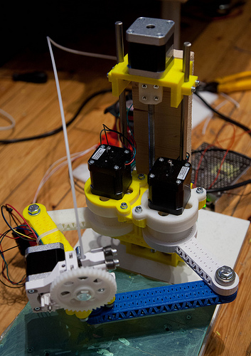
Just got my parallel SCARA moving for the first time:
Parallel SCARA prototype
It's fully printable except for the 608 and 624 bearings and M8 and M4 fasteners. (And NEMA17 motors and electronics, of course.) The things below the motors are printed harmonic drive units with 1/22 reduction ratio. The movement in the video happens at 100 degrees/sec velocity and 1000 degrees/sec*sec acceleration. The drives are cobbled together with spare bits of M8 rod just to see if the thing actually does something, and hey, it does. (It draws a wonky comb with a pen...)
I'll publish the whole thing once I get it into more usable and reliable shape. Also there's no software yet. The math is simple enough for a Rostock-like approach where it happens in the firmware, in realtime, but I'm leaning more towards putting it in the slicer or in a postprocessing step.
|
Re: Printable parallel SCARA September 24, 2012 05:08AM |
Registered: 15 years ago Posts: 376 |
|
Re: Printable parallel SCARA September 24, 2012 05:45AM |
Admin Registered: 16 years ago Posts: 13,884 |
... maybe you can find here some additional infos: [forums.reprap.org]
Viktor
--------
Aufruf zum Projekt "Müll-freie Meere" - [reprap.org] -- Deutsche Facebook-Gruppe - [www.facebook.com]
Call for the project "garbage-free seas" - [reprap.org]
Viktor
--------
Aufruf zum Projekt "Müll-freie Meere" - [reprap.org] -- Deutsche Facebook-Gruppe - [www.facebook.com]
Call for the project "garbage-free seas" - [reprap.org]
|
Re: Printable parallel SCARA September 24, 2012 02:08PM |
Registered: 12 years ago Posts: 313 |
Thanks, Viktor, for the earlier link about the Micro-SCARA robot, that's where I got the concept from.
martinprice2004 Wrote:
-------------------------------------------------------
> Excellent design. It looks like you may benefit
> from having the motors / harmonic drives spaced
> slightly further apart as this would improve
> stability a little and avoid the arm elbows
> inverting.
>
> How are the harmonic drives working out?
I haven't done any durability testing, that will have to wait until I have a proper carriage/chassis for mounting them in. The flexspline required a couple of iterations until I got it working (it's easy to make it too stiff for the steppers to drive). But when it flexes properly and the fit is good, there doesn't seem to be any play in the system. The precision won't be as good as with machined parts, but I'm hoping it will be good enough for general printing use.
Building and (briefly) operating the prototype gave me a good feeling about the whole concept. The drives seemed fast and precise and even the prototype arms didn't sag anywhere near as much as I thought. I'm printing improved arms right now, a bit longer and with a truss construction which should be a lot stiffer still. I'm planning to make the arms (pivot-to-pivot) 120mm and the base axis separation 80mm.
Any ideas for a good lightweight extruder I could put on this? The NEMA17 extruders are probably too heavy, so it would have to be one of those bowden cable ones or maybe a PG35L-driven one.
I also got the crazy idea of putting a mechanism to operate the Z-axis in the reachable area but outside the main work area. That way the arms could go and crank themselves up and down and that would eliminate the Z-motor... there could be a ratchet to crank the Z up or down 0.05 mm per push or something.
|
Re: Printable parallel SCARA September 29, 2012 07:08PM |
Registered: 13 years ago Posts: 1,918 |
ttsalo Wrote:
-------------------------------------------------------
> I also got the crazy idea of putting a mechanism
> to operate the Z-axis in the reachable area but
> outside the main work area. That way the arms
> could go and crank themselves up and down and that
> would eliminate the Z-motor... there could be a
> ratchet to crank the Z up or down 0.05 mm per push
> or something.
That sounds clever, but it means you have to interrupt the printing for quite a while each time you want to move the z axis. That could lead to an ooze problem.
|
Re: Printable parallel SCARA October 08, 2012 07:49PM |
Registered: 12 years ago Posts: 313 |
theodleif Wrote:
-------------------------------------------------------
> That sounds clever, but it means you have to
> interrupt the printing for quite a while each time
> you want to move the z axis. That could lead to an
> ooze problem.
Yes... but if you really wanted to print with just three motors total, it just might work...
I did some simulating in OpenSCAD and the reach and arm angles work a lot better if the second arm sections are somewhat longer than the first ones. It's possible to have a 200x120 mm print area if the first arm sections are 100 mm and the second sections 150 mm (with base axis spacing of 75 mm). WIth that setup there isn't much wasted reachable area outside the rectangular print platform and the design should (at least if the accuracy allows it) be able to print all of it's own parts as well, without splitting any of them. I have a LM8UU-riding, M8-rod-driven Z-carriage design about done, now I just need to design the Z axis ends and get everything printed...
|
Re: Printable parallel SCARA October 09, 2012 08:09AM |
Registered: 15 years ago Posts: 376 |
It seems like there are a few people here thinking along the same lines. My SCARA robot Z axis could easily be adapted to take your harmonic drives on the front, so I suggest you concentrate on getting the XY axes sorted and make sure it has a large working envelope. I have also considered modifying my design to a parallel arm, but using two geared motors rather than the harmonic drives you have. I think the harmonic drives do have more potential than geared motors in the long run.
All the models and firmware are on grabcad below, feel free to chop them about. The Z axis is quite strong now it has a larger stepper on it and would easily accommodate the mass of your front end. I wouldn't get too hung up on the resolution either. The robot will work and print even at low resolution, and you can always change the gearing later.
SCARA Robot
Extruder I think should be a bowden cable, but there is a potential problem. The end nozzle would need to be in a bearing, otherwise you would induce twist in the bowden cable. Just a small point but needs to be included in your arm design.
|
Re: Printable parallel SCARA October 19, 2012 08:49AM |
Registered: 15 years ago Posts: 376 |
Just found this video on youtube.
Parallel SCARA
It has a nice over and under arm configuration and looks like it would make a nice reprapped design.
I assume the Z axis is a vertical plunger type in the tool head. Has anyone done any work on this type of Z axis?
Parallel SCARA
It has a nice over and under arm configuration and looks like it would make a nice reprapped design.
I assume the Z axis is a vertical plunger type in the tool head. Has anyone done any work on this type of Z axis?
|
Re: Printable parallel SCARA October 19, 2012 09:43AM |
Admin Registered: 16 years ago Posts: 13,884 |
... I assume, the Z-axis is separate - look at the holder of the vats, should be lowerable ...
Viktor
--------
Aufruf zum Projekt "Müll-freie Meere" - [reprap.org] -- Deutsche Facebook-Gruppe - [www.facebook.com]
Call for the project "garbage-free seas" - [reprap.org]
Viktor
--------
Aufruf zum Projekt "Müll-freie Meere" - [reprap.org] -- Deutsche Facebook-Gruppe - [www.facebook.com]
Call for the project "garbage-free seas" - [reprap.org]
|
Re: Printable parallel SCARA October 19, 2012 05:26PM |
Registered: 15 years ago Posts: 376 |
|
Re: Printable parallel SCARA October 20, 2012 05:13PM |
Admin Registered: 16 years ago Posts: 13,884 |
... seems to be a vacuum pick-n-place head ... maybe with pneumatic dual-way piston as Z-drive, have some of this sort of linear 'drives' in much bigger sizes - needs speacial logic and controlling for high precision positioning.
A motor driven Z-stage in the table would be easier to handle ...
Viktor
--------
Aufruf zum Projekt "Müll-freie Meere" - [reprap.org] -- Deutsche Facebook-Gruppe - [www.facebook.com]
Call for the project "garbage-free seas" - [reprap.org]
A motor driven Z-stage in the table would be easier to handle ...
Viktor
--------
Aufruf zum Projekt "Müll-freie Meere" - [reprap.org] -- Deutsche Facebook-Gruppe - [www.facebook.com]
Call for the project "garbage-free seas" - [reprap.org]
|
Re: Printable parallel SCARA November 10, 2012 05:05PM |
Registered: 15 years ago Posts: 376 |
|
Re: Printable parallel SCARA November 15, 2012 08:53AM |
Registered: 12 years ago Posts: 313 |
martinprice2004 Wrote:
-------------------------------------------------------
> Another Parallel SCARA arm video here. The working
> envelope looks quite large, but I am not sure its
> able to move in straight lines across all of its
> envelope.
I was looking at that earlier, it sure is an impressive machine...
I have my own design finally ready to print the first ever test object. I just need to steal the heat bed from one of my Prusa2s... I'll try printing a 20mm cube, but I don't expect anyone to recognize it as a cube If I get anything solid printed at all, that'll be a smashing success for a first test.
I'm using a modified Marlin firmware. I looked at how the Rostock project did it and imitated their approach. The firmware divides the cartesian moves into short segments which are then individually mapped into the SCARA arm coordinates and passed to the path planner. The calculation is pretty simple (it's essentially a problem of two intersecting circles), and given the target cartesian point it produces two solutions, with the elbow bent left or right, and picks one based on the arm, since the left arm always has elbow bent to the left and the right to the right.
-------------------------------------------------------
> Another Parallel SCARA arm video here. The working
> envelope looks quite large, but I am not sure its
> able to move in straight lines across all of its
> envelope.
I was looking at that earlier, it sure is an impressive machine...
I have my own design finally ready to print the first ever test object. I just need to steal the heat bed from one of my Prusa2s... I'll try printing a 20mm cube, but I don't expect anyone to recognize it as a cube
If I get anything solid printed at all, that'll be a smashing success for a first test.I'm using a modified Marlin firmware. I looked at how the Rostock project did it and imitated their approach. The firmware divides the cartesian moves into short segments which are then individually mapped into the SCARA arm coordinates and passed to the path planner. The calculation is pretty simple (it's essentially a problem of two intersecting circles), and given the target cartesian point it produces two solutions, with the elbow bent left or right, and picks one based on the arm, since the left arm always has elbow bent to the left and the right to the right.
|
Re: Printable parallel SCARA November 15, 2012 08:22PM |
Registered: 12 years ago Posts: 313 |
Ok, here's the completed prototype printer.
It needs a snazzy name so I thought that Armstrong A1 would be a good one.
And here it prints. 0.25 layer height, 50 degrees/s print speed.
There's a weird sinewave pattern in all X moves, I thought at first that it was somehow caused by the harmonic drives, but now I'm thinking it might be a software problem. The calculations use the float datatype which doesn't have that many bits on the AVR processors, so that might be the cause.
I didn't actually design this to handle a full NEMA17 extruder (I was planning to use a bowden setup or a PG35L extruder), so it's not really stable enough to move that much mass at these speeds and accelerations. Also, the heat bed happened to have a bit of missing tape right under the object, so the first layers became a mess because the middle didn't stick. But at the 2 minute mark in the video it's producing somewhat ok quality (until one of the flexsplines starts breaking at 2:10, you can hear the snapping sound on the video).
It needs a snazzy name so I thought that Armstrong A1 would be a good one.

And here it prints. 0.25 layer height, 50 degrees/s print speed.
There's a weird sinewave pattern in all X moves, I thought at first that it was somehow caused by the harmonic drives, but now I'm thinking it might be a software problem. The calculations use the float datatype which doesn't have that many bits on the AVR processors, so that might be the cause.
I didn't actually design this to handle a full NEMA17 extruder (I was planning to use a bowden setup or a PG35L extruder), so it's not really stable enough to move that much mass at these speeds and accelerations. Also, the heat bed happened to have a bit of missing tape right under the object, so the first layers became a mess because the middle didn't stick. But at the 2 minute mark in the video it's producing somewhat ok quality (until one of the flexsplines starts breaking at 2:10, you can hear the snapping sound on the video).
|
Re: Printable parallel SCARA November 16, 2012 08:22AM |
Registered: 15 years ago Posts: 376 |
Excellent Progress. It doesn't matter that what its making isn't too neat it shows it is feasible which is the main thing. Things will only improve now.
First SCARA print......Another one chalked up for the (ACL) Anti Cartesian League!
I would certainly get a bowden extruder on it as soon as possible to take the load and inertia off the arms.
The sine wave problem in X might be that the arms are not perfectly aligned angularly or of the same length. If you get a twist this would be enough to turn a straight line to a sine curve. For example one of the harmonic drives may be slightly further forward or higher than the other. The error would be multiplied at the tool head. I did notice something similar when setting up my single arm SCARA if the datum switches / datum angle wasn't set up correctly. Do you have datum switches on the arms so you can get the initial angle dialed in the same for each motor?
I'm not convinced that the harmonic drives are yet at the stage where they will work very well.
Are you ready to post up the models as I would love to modify my SCARA to parallel arms? I am interested in the hinges of the arms, they appear to have an external top bearing. how is this? Also what arm lengths are you using, what is the motor pitch distance and how big is the working envelope?
I like the Z axis it looks nice and simple compared to my one. I could see a couple of wooden triangles each side pointing back would make it very rigid.
Very inspirational work.
Edited 1 time(s). Last edit at 11/16/2012 08:26AM by martinprice2004.
|
Re: Printable parallel SCARA November 16, 2012 08:41AM |
Admin Registered: 16 years ago Posts: 13,884 |
... in the PDF linked in this post you have a good comparison between singel- and double-armed scaras and maybe some more hints/ideas 
There are some other parallel-kinematic setups in use, but mostly for high precise and/or really fast applications, so mostly built with really expensive components ...
Viktor
--------
Aufruf zum Projekt "Müll-freie Meere" - [reprap.org] -- Deutsche Facebook-Gruppe - [www.facebook.com]
Call for the project "garbage-free seas" - [reprap.org]
|
Re: Printable parallel SCARA November 16, 2012 07:28PM |
Registered: 12 years ago Posts: 313 |
martinprice2004 Wrote:
-------------------------------------------------------
> I would certainly get a bowden extruder on it as
> soon as possible to take the load and inertia off
> the arms.
I actually have all the necessary parts for a bowden extruder but I have never used a bowden in anything else, so I didn't want to introduce a completely unknown variable into the test...
> The sine wave problem in X might be that the arms
> are not perfectly aligned angularly or of the same
> length. If you get a twist this would be enough to
> turn a straight line to a sine curve. For example
> one of the harmonic drives may be slightly further
> forward or higher than the other. The error would
> be multiplied at the tool head. I did notice
> something similar when setting up my single arm
> SCARA if the datum switches / datum angle wasn't
> set up correctly. Do you have datum switches on
> the arms so you can get the initial angle dialed
> in the same for each motor?
I don't have any homing switches set yet (that's one of the big things missing), so I just eyeballed the positions. It's a good point, but the amplitude of the error waveform is pretty large and since the harmonic drives are straightforward reduction drives (1:25 in the current design), they should not cause that even if the positions are a little off... And I'm quite sure about accuracy of the arm lengths.
> I'm not convinced that the harmonic drives are yet
> at the stage where they will work very well.
It's a bit of an open question. The flexspline of the harmonic drive is by far the most finicky thing in this design. Make it too thick and the NEMA17 won't have the torque to deform it, make it too thin and it will shred... Too small reduction ratio and again the teeth become too hard to deform, too large and the smaller teeth will slip over each other too easily. I went through quite many iterations but the final one ran through the print perimeter (200x120 mm) at least a hundred times, with no load, and up until the halfway point in the print with the heavy extruder and fast/sharp movement.
> Are you ready to post up the models as I would
> love to modify my SCARA to parallel arms? I am
> interested in the hinges of the arms, they appear
> to have an external top bearing. how is this? Also
> what arm lengths are you using, what is the motor
> pitch distance and how big is the working
> envelope?
Base axis spacing is 75 mm, arm first segments are 100 mm and second segments 150 mm. The base and elbow joints all have two 608 bearings each, and they are preloaded with the bolts. The end effector mount has a sort of a slew bearing made with three 624 bearings running in a groove. The working area is 200x120 mm.
I can share the current development with anyone wanting to give it a try, it's just not really ready for a public release...
> I like the Z axis it looks nice and simple
> compared to my one. I could see a couple of wooden
> triangles each side pointing back would make it
> very rigid.
I would like to have a Z axis which would be compatible with both threaded rods and any L-shaped frame you happen to have (heck, you could just bolt this to the nearest wall!), the current one is just the minimal effort one made to work with any two pieces of wood laying around.
|
Re: Printable parallel SCARA November 18, 2012 09:08PM |
Registered: 12 years ago Posts: 313 |
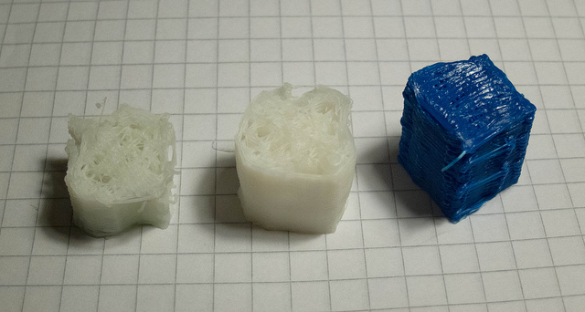
The sources and STLs are up at GitHub. Basic build instructions are in the README file.
I changed to a bowden extruder and did some more test prints.
First (the one printed in the earlier video), second and third prints:
The last, blue one is at 0.3 layer height and was printed at 45 degrees rotated. Looks like the wave pattern in the first one was just wobble from the drives and not a software artifact. The second one shows different wobble (had to stop that before finishing because I ran out of filament) and in the third one the arms didn't have to move in a coordinated way, so it finally looks like a cube.
It looks like most of the inaccuracy stems from the fact that the arm base axes are not as rigid as they should be. The wobble happens not only in X-Y plane but also in Z, so it seems like the rotating wave drivers are making the whole arm wobble a bit. I'll have to think about what to do about this...
I changed to a bowden extruder and did some more test prints.
First (the one printed in the earlier video), second and third prints:

The last, blue one is at 0.3 layer height and was printed at 45 degrees rotated. Looks like the wave pattern in the first one was just wobble from the drives and not a software artifact. The second one shows different wobble (had to stop that before finishing because I ran out of filament) and in the third one the arms didn't have to move in a coordinated way, so it finally looks like a cube.
It looks like most of the inaccuracy stems from the fact that the arm base axes are not as rigid as they should be. The wobble happens not only in X-Y plane but also in Z, so it seems like the rotating wave drivers are making the whole arm wobble a bit. I'll have to think about what to do about this...
|
Re: Printable parallel SCARA November 19, 2012 06:00AM |
Admin Registered: 16 years ago Posts: 13,884 |
... for all sorts of parallel kinematics you need super rigid arms and gears/drives with high accuracies and speeds.
For testing and prototypes you can go away with printed parts -but if you want good results, then either you'll need a better printer for the parts or you have to use conventional made gears and structural parts (milled or injection moulded).
Or you make all parts 10x bigger and try with fabbing furniture and/or builing parts
Viktor
--------
Aufruf zum Projekt "Müll-freie Meere" - [reprap.org] -- Deutsche Facebook-Gruppe - [www.facebook.com]
Call for the project "garbage-free seas" - [reprap.org]
|
Re: Printable parallel SCARA November 26, 2012 08:23AM |
Registered: 12 years ago Posts: 313 |
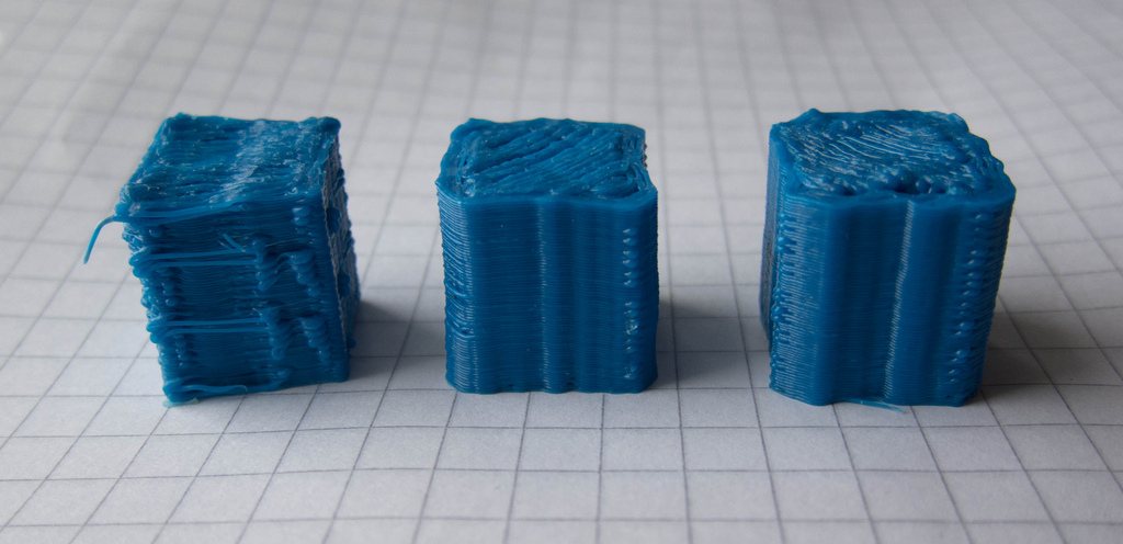
I made the Z-carriage and the arm first segment drive bases beefier and it helped with the arm wobble a lot. Here's some test prints.
The left one is the print from the non-reinforced version. It was printed at 45 degrees, otherwise it would look even worse. The next two have been printed at normal orientation, requiring coordinated movement from the arms when printing the perimeters. The results are still pretty far from cartesian printers, but much better than the first tries. The Z-stability and layer-to-layer repeatability are actually looking quite good.
The middle print was using one ABS flexspline and one from polycarbonate, it's a bit more accurate than the one on the right, which was made using two ABS flexsplines. I might try two PC flexsplines next.
I have the modified firmware up here: Marlin-SCARA. Works like Marlin except for the G-code modifications described in the README file and the extra options in configuration.h. There may still be something funny in how the G92 works, I'll have to look into that, but it does do the actual print just fine.
|
Re: Printable parallel SCARA March 29, 2013 06:08AM |
Quote
ttsa;o
The flexspline of the harmonic drive is by far the most finicky thing in this design. Make it too thick and the NEMA17 won't have the torque to deform it, make it too thin and it will shred..versize the
Does printing it in nylon help? Good combo of flex and toughness.
Has anyone tried split annulus epicyclic gearing instead?Quote
martinprice2004
I'm not convinced that the harmonic drives are yet at the stage where they will work very well.

In the picture, the white housing is stationary, the white sun gear is the input and the black housing is the output. The annulus gears (ring gears) are fixed to the housings. (The picture lacks a planetary carrier, which you'd probably want in a precision application.)
Gear ratio is pretty easy to figure out if you drive the planetary carrier. Say you wanted 25:1 with 3 simple planetary gears. This means 3 places where the teeth are in phase, So the stationary ring could have 3x25xn teeth and the output ring gear would have 3x(25+-1)xn teeth. If you're willing to specialize your planetary gears then design options widen considerably. See Wikipedia
I also would be tempted to put the planetary gears on a carrier, drive the carrier and perhaps discard the sun. Then thicken the gears, oversize the planetary gears a bit, reduce their infill and print them in nylon to give them some flex. That would give you a bigger contact patch with the annulus gears and hopefully give you the very low backlash quality of harmonic drive. (But I haven't tried any of this, so I'd start simply.)
Sorry, only registered users may post in this forum.