Generation 7 Electronics Development
Posted by Traumflug
|
Re: Generation 7 Electronics Development December 04, 2011 03:52AM |
Registered: 13 years ago Posts: 7,616 |
Gen7 is just as much "final" as the other RepRap electronics 
That said, there is no such thing like a "final" design. Development always continues.
Not only for your convenience, the extension board connector currently in the design stage will have the serial lines available, so you'll be able to plug in custom serial connectors.
That said, there is no such thing like a "final" design. Development always continues.
Not only for your convenience, the extension board connector currently in the design stage will have the serial lines available, so you'll be able to plug in custom serial connectors.
| Generation 7 Electronics | Teacup Firmware | RepRap DIY |
|
Finch
Re: Generation 7 Electronics Development December 11, 2011 05:36AM |
|
Re: Generation 7 Electronics Development December 11, 2011 07:02AM |
Registered: 13 years ago Posts: 7,616 |
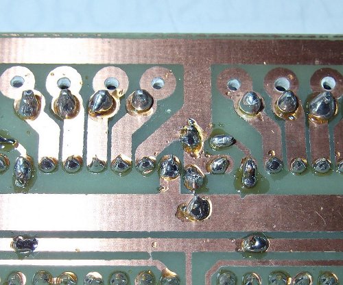
Timeout means, there is no connection at all. Possible errors include: wrong COM port, no juice (voltage supply) for the ATmega, a miswired connector, shorts on the board and cold solder junctions.
Regarding shorts and cold joints, do you see both of them?
Edited 1 time(s). Last edit at 12/11/2011 07:03AM by Traumflug.
Regarding shorts and cold joints, do you see both of them?

Edited 1 time(s). Last edit at 12/11/2011 07:03AM by Traumflug.
| Generation 7 Electronics | Teacup Firmware | RepRap DIY |
|
Finch
Re: Generation 7 Electronics Development December 11, 2011 01:33PM |
Thank you Traumflug
Is my USB-ttl connection ok?
converter gen7
1. (GND) - pin1 (pin on left)
2. (+5V) - pin 3
3. (TxD) - pin4
4. (RxD) - pin5
5. (RTS) - pin6
6. (CTS) - not conected

Is my USB-ttl connection ok?
converter gen7
1. (GND) - pin1 (pin on left)
2. (+5V) - pin 3
3. (TxD) - pin4
4. (RxD) - pin5
5. (RTS) - pin6
6. (CTS) - not conected
|
Re: Generation 7 Electronics Development December 12, 2011 04:03AM |
Registered: 13 years ago Posts: 7,616 |
Well done for the bridge, cold joints are all in the upper row as well.
The serial connection is described in the wiki: [reprap.org]
The serial connection is described in the wiki: [reprap.org]
| Generation 7 Electronics | Teacup Firmware | RepRap DIY |
|
Finch
Re: Generation 7 Electronics Development December 12, 2011 03:36PM |
I ve read it many times but I dont understand what to do with CTS. Should I connect it on pin2 or leave it disconected.
And for firmware problem. The led lights up (atmega has power), com port is ok, all voltage on gen7 plate is ok, baud rate is 115200.
Is anything wrong with settings on picture?
And for firmware problem. The led lights up (atmega has power), com port is ok, all voltage on gen7 plate is ok, baud rate is 115200.
Is anything wrong with settings on picture?

|
Re: Generation 7 Electronics Development December 12, 2011 08:59PM |
Registered: 13 years ago Posts: 7,616 |
Hmm. Which USB-TTL connector are you talking about, after all? "Pin 2" isn't really helpful, as different devices have different signals on this pin.
Also, what makes you think there's a bootloader on the ATmega? If you have a programmer, upload a firmware with the programmer, bypassing the bootloader. A Firmware sending some serial stuff at 9600 baud, like this one: [github.com] This will send a signal on ATmega's TxD, which should be received by your converter's RxD. Just two pins, TxD and GND, no further signals.
If you have the ATmega from me or Paoparts, this firmware is uploaded already, along with the bootloader.
With one pin working, you can identify the other TxD/RxD pair (opposite direction). Three pins are sufficient for full communications in both directions. Like shown for the E'go adapter, shown on the same wiki page. 5V is obsolete, unless you want to drive the ATmega from USB.
If you don't have the converter's RTS connected to the Reset line, you have to reset the ATmega manually. Hit the reset button just before or just after Arduino IDE reports the size of your firmware when attempting to upload. Opinions vary on the exact timing, so experiment a bit.
| Generation 7 Electronics | Teacup Firmware | RepRap DIY |
|
Finch
Re: Generation 7 Electronics Development December 13, 2011 10:23AM |
No no I talk about pin2 on the gen7 board. Should I connect CTS from USB-TTL connector to pin 2 on gen7 or should I leave it disconected. Becouse pin1 and pin2 on gen7 are both GND.
And I have this connector:
http://www.ebay.com/itm/USB-TTL-5V-Serial-Cable-FTDI-FT232-Arduino-UNO-mini-duemilanove-Mega-/220910874097?pt=LH_DefaultDomain_0&hash=item336f506df1
Sorry for bad englis, hope you uderstand what I mean.
I talk about pin2 on the gen7 board. Should I connect CTS from USB-TTL connector to pin 2 on gen7 or should I leave it disconected. Becouse pin1 and pin2 on gen7 are both GND.And I have this connector:
http://www.ebay.com/itm/USB-TTL-5V-Serial-Cable-FTDI-FT232-Arduino-UNO-mini-duemilanove-Mega-/220910874097?pt=LH_DefaultDomain_0&hash=item336f506df1
Sorry for bad englis, hope you uderstand what I mean.
|
Re: Generation 7 Electronics Development December 14, 2011 03:41AM |
Registered: 13 years ago Posts: 7,616 |
Quote
Should I connect CTS from USB-TTL connector to pin 2 on gen7 or should I leave it disconected.
This matters if you configure your serial port for hardware handshake, only. See "Flow control" in the left of the two windows in the picture you posted above. Hardware handshake on the PC side and auto-reset on the ATmega side don't play well together, so everybody is using no handshake.
This cable looks pretty much like it works without changing anything at all.
| Generation 7 Electronics | Teacup Firmware | RepRap DIY |
|
Re: Generation 7 Electronics Development December 19, 2011 11:18PM |
Hello,
Tonight I was able to power on my Gen7 1.3.1 for the first time. Two issues that I am having:
1) When using an ATX power supply, it appears to go into a 'low-draw' standby state if a stepper doesn't turn within 3 seconds of power on and won't wake up. (*fixed* this by connecting a 12v fan)
2) Tool temp sensor reads 0 while the PSU is on. If I disconnect the ATX 20-pin and jumper for molex only (forcing the ATX PSU on with a jumper AND still using a fan to prevent sleep state, the tool temp works just fine.
Any suggestions before I replace this scum-bag PSU?
Otherwise everything works fine so far.... other then scratching my head for an hour until I turned up the pots on the stepper drivers.
|
Re: Generation 7 Electronics Development December 20, 2011 05:09AM |
Registered: 13 years ago Posts: 7,616 |
Quote
1) When using an ATX power supply, it appears to go into a 'low-draw' standby state if a stepper doesn't turn within 3 seconds of power on and won't wake up. (*fixed* this by connecting a 12v fan)
Many PSUs do this, it's allowed in in the ATX power supply specification. The load should be connected to a 5V rail.
Quote
2) Tool temp sensor reads 0 while the PSU is on. If I disconnect the ATX 20-pin and jumper for molex only (forcing the ATX PSU on with a jumper AND still using a fan to prevent sleep state, the tool temp works just fine.
Here's probably not the PSU at fault. Sounds like a bad solder point or interrupted track or something. A voltage meter should find out more.
| Generation 7 Electronics | Teacup Firmware | RepRap DIY |
|
Re: Generation 7 Electronics Development December 20, 2011 05:26AM |
Registered: 13 years ago Posts: 7,616 |
Generation 7 Electronics is now know to run Repetier Firmware successfully: [reprap.org]
A big Thank You to Bryanandamiee!
A big Thank You to Bryanandamiee!
| Generation 7 Electronics | Teacup Firmware | RepRap DIY |
|
Re: Generation 7 Electronics Development December 22, 2011 01:37PM |
Registered: 13 years ago Posts: 44 |
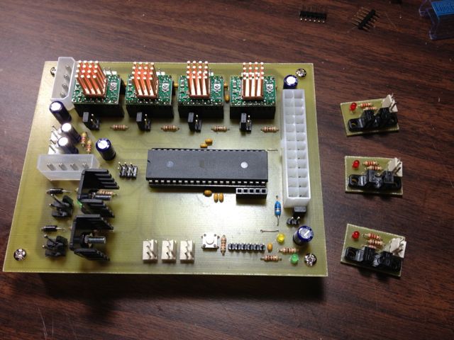
I'm finally getting around to finishing a gen7 version 1.2 board, and I just connected the power to check the voltages (Using only 4 pin molex connecter, jumper is correctly set). When I turned my power supply on, every led on the board lit up. I have the 3 MOSFETS soldered in, but the ATmega is not in place.
I'm wondering if those 3 LEDs next to the MOSFETS should be on. The other two are as they should be.
Thanks-
I'm wondering if those 3 LEDs next to the MOSFETS should be on. The other two are as they should be.
Thanks-
|
Re: Generation 7 Electronics Development December 22, 2011 07:01PM |
Registered: 13 years ago Posts: 632 |
|
Re: Generation 7 Electronics Development December 22, 2011 07:30PM |
Registered: 13 years ago Posts: 44 |
Thank you very much. Trying to pick up where I left off several months ago, but I have no idea where I left off. For some reason I had everything put together with only the ATX 20 pin connector wired up, so I need to add the 4pin molex and get a new atmega (screwed up the fuses, won't recognise device signature now  )
)
)
|
Re: Generation 7 Electronics Development December 26, 2011 11:44AM |
Registered: 13 years ago Posts: 632 |
For the near future (Repetier firmware V 0.41) if you want Repetier firmware to do PWM heater control on Gen7 you'll need to refer to this post. Or you can just turn off PWM and do on/off control, but temps are far more stable with PWM. Changes will go into the next revision and then you won't have to change code to get it to work.
[forums.reprap.org] .
[forums.reprap.org] .
|
Re: Generation 7 Electronics Development January 03, 2012 03:35AM |
Registered: 12 years ago Posts: 103 |
|
Re: Generation 7 Electronics Development January 03, 2012 03:51PM |
Registered: 14 years ago Posts: 80 |
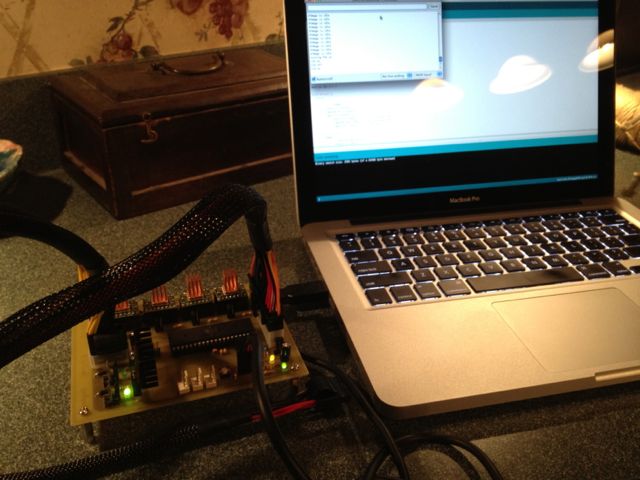
I am a bit stuck here.. soldered up and tested the Gen 7 electronics all accruing to the wiki and confirmed the volts etc....
Uploaded the 'test code' as explained on the wiki.. and yes i can see my psu starting up and my led of the psi turn on .. Then i see the heater Leds on and off.. Opened up the terminal to see the comms.. all ok ..
to verify if I am not locked in a preloaded firmware i changed the code slightly to confirm it is 'my' code running :-) and it still gives me the all clear sign..
Then I uploaded the firmware of repeater.. (already have it running on a ramps board.. ) I cannot get connected in any host.. repeater/pronterface.. Checked the baud rates etc..
Then I tried the fiveD gen 7 as mentioned on the wiki.. but also there I cannot get the host connected..
Could somebody hint me in the right direction..??! Am i missing something .. do I need some other cable then the one I use for uploading my firmware.. ( Iguessed not, but it is a USB-TTL cable and known to work as my firmware is getting uploaded.. )
PSU is switched on but asleep and waiting for things to happen..
With kind regards..
Edited 1 time(s). Last edit at 01/03/2012 05:25PM by mhensen.
|
Re: Generation 7 Electronics Development January 04, 2012 04:44AM |
Registered: 13 years ago Posts: 7,616 |
@mhensen, you have to make sure you compile your firmware for the right clock frequency. Firmware default is usually 16 MHz, many Gen7s run 20 MHz. With the wrong clock frequency, baud rate will be wrong as well.
@metzench, have a look for the work of Alfons3 on Github.
@metzench, have a look for the work of Alfons3 on Github.
| Generation 7 Electronics | Teacup Firmware | RepRap DIY |
|
Re: Generation 7 Electronics Development January 04, 2012 04:53AM |
Registered: 12 years ago Posts: 103 |
|
Re: Generation 7 Electronics Development January 04, 2012 06:25AM |
Registered: 14 years ago Posts: 80 |
I rechecked and reinstalled the software for the arduino .. but I cannot get it to communicate between the rewrap software and the board.
I traced all the lines with a knife to make sure no solders were touching .. I can confirm it is atmega 644 + 20mhz crystal ... (your own package :-) ) and I can upload firmwares without any problems .. confirmed the drivers are running on the correct speed.. but do I have to check the firmware code is elf for the 16MHZ or is this done by the board selection of the compile and upload?
I traced all the lines with a knife to make sure no solders were touching .. I can confirm it is atmega 644 + 20mhz crystal ... (your own package :-) ) and I can upload firmwares without any problems .. confirmed the drivers are running on the correct speed.. but do I have to check the firmware code is elf for the 16MHZ or is this done by the board selection of the compile and upload?
|
Re: Generation 7 Electronics Development January 04, 2012 01:33PM |
Registered: 14 years ago Posts: 80 |
Well I have been busy looking at makefiles .. looking at comm port settings .. try and get any response from the atmega but for now it only seems to accept the firmware and do nothing at all.. I don;t know where to look for next .. I have updated all the drivers, switched OS.. but no luck so far.. Soldering the smd's on the ramps seemed easier then all trouble I am having now..
Please if somebody has any suggestion?! Idea's to check.. I have checked all solders.. and beeped them to check for shortcuts.. so far nothing is wrong on the board..
Just a guess .. if the test firmware with the power on and off of the less en psi runs and communicates back what could be wrong.. the crystal ?!
Fow now I am completely lost...please help :-) I did numerous uploads of firmware.. from repeater/sprinter to the test version. opened up the hosts of repetier and pronterface..
rebooted the PC from win 7 to win xp.. nothing.. Only the test firmware is the one that keeps working when I upload that one.. so I have a serial connection.. otherwise I should;t be able to upload... after every reset .. power en PSU and blink the 2 leds.. turn of PSU and in sleep mode..
Then I tried all various comm settings but what are the correct settings.. ?!? I am really lost .. not able to debug this problem makes me stare at the board in the hope that it starts working.. no smoke , nothing gets hot or even warm...
Edit update:
hmm.. Tried to reflash the chip.. but in de avrdude I keep getting stk500_GetSync() Not in Sync :resp=0x00 following the guide in the wiki.. right at the beginning with writing fuses
tried if via the arduino desktop tool and via avrdude command shell..
I am at the point of giving up.. :-(
But I am still able to change and upload the test PDE .. even change and reupload and I can identify it is another program! ???????????!???
Running (trying to run Gen 7 with atmega 644 20mhz.. ..
Update.. Finally .. I found the problem .. pin 33 and 31 of the arduino were shorted...now I have comm and things looks promising.. I left the initial message as it might help others that would run in these problems.. :-)
Edited 7 time(s). Last edit at 01/05/2012 08:06AM by mhensen.
|
Re: Generation 7 Electronics Development January 05, 2012 04:34PM |
Registered: 13 years ago Posts: 7,616 |
Quote
Any plans to merge [Alfons3's enhancements] sometime?
Sometime. You know, since the PrintrBot story it's clear one has to make complete machines and beefing up details isn't honored. OK, perhaps a bit exaggerating, but things are goiung this direction.
Quote
Finally .. I found the problem
Sometimes it's really tricky. You know, the guy with the board in the picture a few posts above stared at his work for weeks and couldn't find it. After he finally sent it to me, it took me less than a minute. Not because I'm brighter than him, but because ... well, I don't know.
The unfortunate thing is, such things can't be seen remotely. I'm glad you finally found the issue.
| Generation 7 Electronics | Teacup Firmware | RepRap DIY |
|
Re: Generation 7 Electronics Development January 23, 2012 11:31PM |
Registered: 12 years ago Posts: 7 |
Traumflug,
Thanks very much for all your hard work designing this board. I've just successfully finished printing and etching a board using Press-N-Peel paper. The hardest part was the ironing. Took six trys to get the iron temperature just right.
Greg
Thanks very much for all your hard work designing this board. I've just successfully finished printing and etching a board using Press-N-Peel paper. The hardest part was the ironing. Took six trys to get the iron temperature just right.
Greg
|
Re: Generation 7 Electronics Development January 24, 2012 05:51AM |
Registered: 13 years ago Posts: 7,616 |
Oh, that's a snapshot of the current development. Does it work?
| Generation 7 Electronics | Teacup Firmware | RepRap DIY |
|
Re: Generation 7 Electronics Development January 24, 2012 08:21AM |
Registered: 12 years ago Posts: 7 |
I reviewed your changes in the github repository and they all seemed reasonable, so I decided to use the latest. It passed the smoke test. I've successfully uploaded the boot loader and then ran into a problem.
When I try to build a SetupTest I get errors that 'Serial' and 'delay' were not declared in this scope. I get similar errors if I try to write a simple sketch. I've installed the Gen7 Arduino files into the proper location. The four Gen7 boards show up in the Arduino menu.
I'm running Arduino 1.0 under OS X 10.7.2 if that matters. I've got an Ubuntu VM just in case I need it.
It was late by the time I ran into this so I didn't really try too hard to solve. I'll have a look at it again tonight.
I have plastic parts for a Sells Mendel. I'm still waiting on hardware. In the meantime I was going to write some more small test sketches that exercise each of the different functionality.
BTW, I've read the 'PCB Milling' topic. Its unclear what machine you ended using to mill your boards. Are you using a WolfStrap or some other machine?
|
Re: Generation 7 Electronics Development January 24, 2012 10:26PM |
Registered: 12 years ago Posts: 7 |
Ok. My problem appears to be due to Arduino 1.0. Your Gen7 dist contains "WProgram.h". Arduino 1.0 now expects "Arduino.h". I worked around this easily by just adding "Gen7/cores/arduino/Arduino.h" that contained the single line '#include "WProgram.h"'. I think if you add this one file it will work for anyone with Arduino 018 or higher, including 1.0.
I uploaded SetupTest to the board. PSU came on. Heater light blinked. PSU went off. I'd say it works.
While I'm waiting for the rest of my hardware I'm going to write some small sketches to test the endstops, both heaters, temp inputs, and steppers. I'll post them in case anyone is interested.
Thanks once again for an awesome design
|
Re: Generation 7 Electronics Development January 25, 2012 04:44AM |
Registered: 13 years ago Posts: 7,616 |
Quote
Its unclear what machine you ended using to mill your boards. Are you using a WolfStrap or some other machine?
Yes, it's a WolfStrap. Carefully adjusted, it works quite reasonably. See the "Gen7 Stories" Wiki page.
Great you could solve the thing with Arduino 1.0 while I was asleep on this side of the planet
| Generation 7 Electronics | Teacup Firmware | RepRap DIY |
|
Re: Generation 7 Electronics Development January 29, 2012 07:55PM |
ggal625 Wrote:
-------------------------------------------------------
> Ok. My problem appears to be due to Arduino 1.0.
> Your Gen7 dist contains "WProgram.h". Arduino 1.0
> now expects "Arduino.h". I worked around this
> easily by just adding
> "Gen7/cores/arduino/Arduino.h" that contained the
> single line '#include "WProgram.h"'. I think if
> you add this one file it will work for anyone with
> Arduino 018 or higher, including 1.0.
Yes, but I'm not sure that will work with some of the other firmware out there. Some of it seems quite picky.
> While I'm waiting for the rest of my hardware I'm
> going to write some small sketches to test the
> endstops, both heaters, temp inputs, and steppers.
> I'll post them in case anyone is interested.
I'd like to see this when you're finished. Printrun/pronterface is a good test for some of this, but as I worked my way up to running Teacup/Pronterface, it would have been nice to have some more sanity checks.
For example, I had a short on my one of my motor drivers that did not turn up until the driver code tried to enable the motors. I found it by adding debug code to find out where the reset occurred. But I was thinking it would have been nice to have some software that said "About to enable motor control on pin Axx" just beforehand so I could see where it reset. In fact, I think it could even notice the brownout condition and report the last thing it tried (from eeprom?) with the right timings.
I'm not sure how useful it would be once you get "out of the gate", though.
Phil
|
Re: Generation 7 Electronics Development January 29, 2012 08:13PM |
I have my Gen7 board built and working now (Thanks, Markus!). But I haven't printed anything yet.
This week I added a heatbed similar to Adrian's heated bed. It works pretty well. Last night I watched it get right up to 100C and rest there like it was supposed to.
But then I noticed something funny. The two black heat sinks on my MOSFETs were no longer black. Now one was black and the other was copper colored -- bare metal. The heat from the MOSFET vaporized the paint. Also, the MOSFET is now sporting a hole and an "always-on" feature.
I replaced the bad MOSFET with another one I happened to have around along with a massively oversized heat sink and some thermal paste. This heat sink still overheats, though, so I also had to add a fan.
I'm wondering about this failure, of course. I almost replaced the thing with a relay, but I couldn't find a suitable one in my parts drawer. But a relay might be much more suitable here. Or maybe I should have used Adrian's schematic and placed a secondary MOSFET controller on the heat bed itself. At least then the bed-as-a-heat-sink would be a good use for the waste heat.
Since I am driving my extruder hot end directly with the other MOSFET, I didn't think I needed 2nd stage transistor for this heat bed. Was I overreaching?
My current theories are that the MOSFET overheated (overheats still) because the PWM is too fast for it and causes it to waste too much time switching (inefficient). I don't grok transistor datasheets too well, but this IRFZ44N looks like it should be able to handle the switching load. But it also says that it will dissipate 75W(!), which seems like a lot to me.
I'm planning to go experiment with the PWM and see if I can tone this down a bit. After all, a heat bed doesn't need such fine tuned (PID) control, I would think, since the thermal mass is so huge.
Any advice or commiseration is welcome.
Phil


Sorry, only registered users may post in this forum.