Generation 7 Electronics Development
Posted by Traumflug
|
Re: Generation 7 Electronics Development January 23, 2013 01:39PM |
Registered: 11 years ago Posts: 3 |
Hi,
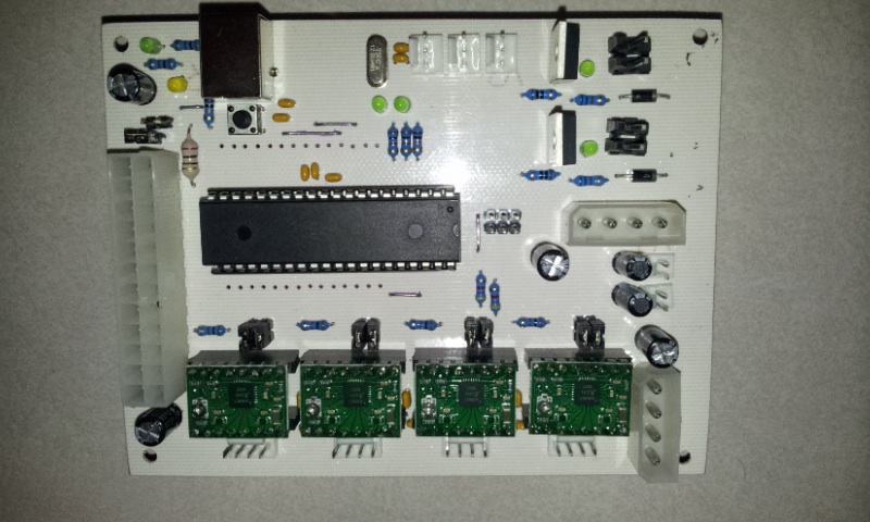
could anyone post a close up picture of the finished board with components. I'm not sure how to solder the MCP2200. (Btw is it this one? MCP2200 Reichelt)
A picture of the toner transfer would also be appriciated.
Thanks!
could anyone post a close up picture of the finished board with components. I'm not sure how to solder the MCP2200. (Btw is it this one? MCP2200 Reichelt)
A picture of the toner transfer would also be appriciated.
Thanks!
|
Re: Generation 7 Electronics Development January 24, 2013 07:30AM |
Registered: 11 years ago Posts: 258 |
The component looks right.
You can take a look at this picture to solder it correctly:
[www.reprap.org]
You can take a look at this picture to solder it correctly:
[www.reprap.org]
|
Re: Generation 7 Electronics Development January 24, 2013 07:30AM |
Registered: 13 years ago Posts: 7,616 |
Yes, it's this MCP2200. On how to solder it, see [reprap.org] . I hope I can provide a picture of the same on the v1.5 board in a few days.
| Generation 7 Electronics | Teacup Firmware | RepRap DIY |
|
Re: Generation 7 Electronics Development January 24, 2013 12:36PM |
Registered: 11 years ago Posts: 3 |
|
Re: Generation 7 Electronics Development February 08, 2013 09:55PM |
Registered: 12 years ago Posts: 31 |
|
Re: Generation 7 Electronics Development February 09, 2013 07:05AM |
Registered: 13 years ago Posts: 7,616 |
Looks very nice. I took the freedom to put it into the hall of fame: [reprap.org] 
| Generation 7 Electronics | Teacup Firmware | RepRap DIY |
|
Re: Generation 7 Electronics Development February 10, 2013 02:03AM |
Registered: 11 years ago Posts: 121 |
I agree with Sonex...
That MCP2200 is gold. More than 6 weeks in, running 4 of the new Gen 7 v1.5s and it works so well I've pretty much stopped development of Hostless printing (LCD/SD). With FTDI adapters/cables I was constantly having serial issues which frustrated me so much that all I wanted to do was get printing off SD
Now I run them off a Raspberry Pi with the Gen 7 1.5
|
Re: Generation 7 Electronics Development February 12, 2013 05:23PM |
Hi all! Last weekend I've finish soldering my Gen7 1.5 board and everything seems to be fine..well not everything.
I have problems with MCP2200. The first problem was solved just resoldering the IC. At the moment this is the situation, I CAN'T upload the code to ATmega1284 by USB but I CAN upload the firmware (Teacup) by USBTiny and use GEN7 1.5 normally. Then everything works fine... (I have try Replicatorg40 and Cura12.12 and I can move the steppers, heat the hotend and the heat bed)
So the problems seems to be solved, but looking at GEN7 1.5 schematics I'have realize that Tx and Rx pins from MCP2200 are connected to RXD0 and TXD0 respectively, (are they switched or this config is the good one?) Also I found RTS connected to reset, (instead of RST)?
Thanks to everybody specially for Traumflug
and everything seems to be fine..well not everything.I have problems with MCP2200. The first problem was solved just resoldering the IC. At the moment this is the situation, I CAN'T upload the code to ATmega1284 by USB but I CAN upload the firmware (Teacup) by USBTiny and use GEN7 1.5 normally. Then everything works fine... (I have try Replicatorg40 and Cura12.12 and I can move the steppers, heat the hotend and the heat bed)
So the problems seems to be solved, but looking at GEN7 1.5 schematics I'have realize that Tx and Rx pins from MCP2200 are connected to RXD0 and TXD0 respectively, (are they switched or this config is the good one?) Also I found RTS connected to reset, (instead of RST)?
Thanks to everybody specially for Traumflug
|
Re: Generation 7 Electronics Development February 12, 2013 05:56PM |
Registered: 12 years ago Posts: 1,236 |
Good news!
I have been working on firmware for Gen7-ARM board which Traumflug has sent me, I now have a port of Teacup to LPC1114 which is mostly functional. There are several things that are not yet ported, for example PWM control.
Video of Gen7-ARM in action [youtu.be]
I made a few modifications to the hardware, an essential one is a pull up resistor on E_STEP (PIO0_4), I used 4k7. The others were to provide separate inputs for endstops and access to PIO0_1 to enable bootloader.
Firmware is here [github.com]. I am building with a version of gcc-arm from CodeSourcery but in principle any recent gcc-arm toolchain should work. The code builds from makefile under Windows or Linux. I am downloading using the Windows tool FlashMagic, haven't tried the Linux tool yet.
Now I have a working build, I will try to make it compatible with the Arduino 1.5.2 IDE and perhaps get the AVR build working, and implement remaining unported features.
Thanks to Traumflug, the Gen7-ARM is really well made and works nicely overall.
|
Re: Generation 7 Electronics Development February 13, 2013 05:37AM |
Registered: 13 years ago Posts: 7,616 |
Quote
JP.Ruiz
At the moment this is the situation, I CAN'T upload the code to ATmega1284 by USB but I CAN upload the firmware (Teacup) by USBTiny and use GEN7 1.5 normally.
Once you've uploaded something with a programmer the bootloader is gone and you have to re-upload it.
And yes, the MCP2200's TxD has to be connected to the ATmegas RxD and vice versa.
Quote
bobc
Video of Gen7-ARM in action [youtu.be]
That's just awesome!
| Generation 7 Electronics | Teacup Firmware | RepRap DIY |
|
Re: Generation 7 Electronics Development February 13, 2013 08:58AM |
|
Re: Generation 7 Electronics Development February 14, 2013 06:21AM |
Registered: 13 years ago Posts: 7,616 |
RST is ReSeT, isn't it? This resets the MCP2200. I deliberately decided this isn't needed. It would require a second Reset button, which I consider to be too confusing.
RTS is Ready To Send, aka. hardware flow control. It's sort of misused to reset the ATmega when an serial connection is established. Arduino people call this "auto-reset", it makes pressing the reset button when uploading via the bootloader obsolete.
RTS is Ready To Send, aka. hardware flow control. It's sort of misused to reset the ATmega when an serial connection is established. Arduino people call this "auto-reset", it makes pressing the reset button when uploading via the bootloader obsolete.
| Generation 7 Electronics | Teacup Firmware | RepRap DIY |
|
Re: Generation 7 Electronics Development February 14, 2013 09:16AM |
|
Re: Generation 7 Electronics Development February 20, 2013 10:02PM |
Registered: 11 years ago Posts: 64 |
Hi,
I'm not sure if this is the correct thread to post this, so sorry if it's not.
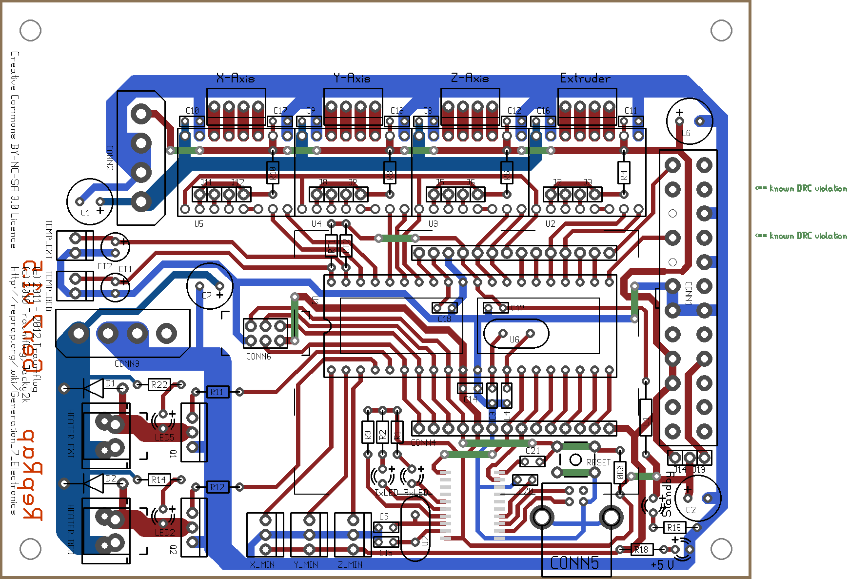
I'm doing some work on to learning gEDA, and my first attempt is to play with the current Gen7Board layout. This is a work-in-progress, so before to continue, I want to know if this changes are correct.
I changed some paths in the stepper drivers header to be able to place them without separation, and to allow to use a 2 x 32 pin header. The 12V rail is a bit smaller, so I think this could be a problem. The 5V rail has bridges (one more than current v1.5), and I also think that this could be a problem.
I also changed the position of C8, C9, C10 and C16.
The main goal is to try to reduce the size of the board, but can you tell me the pros (if any) and cons to this approach?
Thanks
Edited 2 time(s). Last edit at 02/22/2013 08:47AM by xoan.
I'm not sure if this is the correct thread to post this, so sorry if it's not.
I'm doing some work on to learning gEDA, and my first attempt is to play with the current Gen7Board layout. This is a work-in-progress, so before to continue, I want to know if this changes are correct.
I changed some paths in the stepper drivers header to be able to place them without separation, and to allow to use a 2 x 32 pin header. The 12V rail is a bit smaller, so I think this could be a problem. The 5V rail has bridges (one more than current v1.5), and I also think that this could be a problem.
I also changed the position of C8, C9, C10 and C16.
The main goal is to try to reduce the size of the board, but can you tell me the pros (if any) and cons to this approach?
Thanks
Edited 2 time(s). Last edit at 02/22/2013 08:47AM by xoan.
|
Re: Generation 7 Electronics Development February 21, 2013 06:09PM |
Registered: 12 years ago Posts: 39 |
I recently switched over to gen7 1.5, and it's been going pretty well except for one small annoyance. It seems the MCP2200 will only enumerate once with the host system. If the USB is unplugged after that and plugged back in you have to power cycle the board, wait for the caps to discharge, and plug it back in. I'm assuming this is a side effect of powering the MCP2200 from the board instead of the usb port and not shoddy soldering on my part, but I'm less than 100% positive on that one. Is this expected behavior?
If this is considered normal, I notice that the MCP2200's RST pin is held high by a pull up resistor connected to the PSU's V+. If this pull up were instead connected to the currently unused USB V+ (and maybe a pull down hooked up to GND somewhere), wouldn't this force the MCP2200 to remain in reset until the USB cable is plugged in, thus enumerating properly every time? Would there be any unintended side effects caused by this change?
Edited 1 time(s). Last edit at 02/21/2013 06:10PM by Rezer.
|
Re: Generation 7 Electronics Development February 22, 2013 05:44AM |
Registered: 12 years ago Posts: 39 |
So I went ahead and gave the above a try...turns out there's an internal pullup on the order of 33K, so just letting the RST pin float won't cause a reset. Fortunately (and unfortunately) there's a massive inductive voltage spike on the order of +/- 12V for a few ms when plugging in the USB cable that happens to cause a reset and didn't damage the chip, despite being well outside the maximum operating range. So...not the best solution.
I figured I'd try a pull down with a pull up hooked to the USB port, and the following seems to work pretty reliably and keeps the voltage spike in check:
This lowers the RST pin to around .9 volts when unplugged and 4.2 volts with USB plugged in...and forces the MCP2200 to reset every time and enumerate properly. Whether this is a solution that anybody but me has a desire for, I have no clue
Edit: Updated image with capacitor in the right place. The former circuit was causing unexpected resets on occasion, this one works much better. Also note that this is meant to replace the R3 pullup on board 1.5.
Edited 3 time(s). Last edit at 02/23/2013 02:54AM by Rezer.
I figured I'd try a pull down with a pull up hooked to the USB port, and the following seems to work pretty reliably and keeps the voltage spike in check:

This lowers the RST pin to around .9 volts when unplugged and 4.2 volts with USB plugged in...and forces the MCP2200 to reset every time and enumerate properly. Whether this is a solution that anybody but me has a desire for, I have no clue
Edit: Updated image with capacitor in the right place. The former circuit was causing unexpected resets on occasion, this one works much better. Also note that this is meant to replace the R3 pullup on board 1.5.
Edited 3 time(s). Last edit at 02/23/2013 02:54AM by Rezer.
|
Re: Generation 7 Electronics Development February 22, 2013 07:13AM |
Registered: 13 years ago Posts: 7,616 |
@xoan: Nice work!
@Rezer: the reason to power the USB adapter by the PSU is, the device should vanish on the host PC if its turned off. At least I consider this to be a good idea. You also get rid of all trouble when the PSUs and USBs 5V don't match well, of course.
Your idea to use USB 5V for just resetting the chip seems to be an excellent idea!
This 12V spike isn't within the USB specification, is it? Would a 5.5V Z-diode or a 10 uF cap also work? To some extent I could also imagine to let the chip's protection diodes handle this peak. I'm always searching for the solution with the lowest pin count, of course.
| Generation 7 Electronics | Teacup Firmware | RepRap DIY |
|
Re: Generation 7 Electronics Development February 22, 2013 08:20AM |
Registered: 13 years ago Posts: 7,616 |
Got this by PM:
The voltages for motors (upper disk power connector) and heaters (lower disk power connector) can be different. Motors can handle between 8V and 30V (limited by electrolytic caps and Pololus), Heaters can handle between 1V and 30V (limited by the MOSFET and the indicator LEDs).
Regarding currents, the MOSFET is specified for 140 amps, so you have room for 30A. For voltages above 14V you have to replace R14 and R22 with a higher value or the indicator LEDs will burn away. 2k2 ohms is a good choice for 24V, everything above 1k5 is in range for the LEDs at 24V.
Another limit is the disk power connector its self. Likely it can't handle 30A without melting, so you have to solder the supply wires directly onto the board.
For high power heated beds I'd also consider those driven by mains (110/220V) electricity. Solid State Relays (SSRs) can't do PWM but work well when driven with an on/off strategy. Then you need no MOSFET at all, a pin from the ATmega can go directly to the SSR.
Quote
I have built a slightly larger mendelmax model 300x300 and I am thinking of using a homemade PCB heated bed (400W), the ones online as too small for the bed. My question is, is it possible to connect a heated bed to the gen7 electronics to to control it and power the board seperatly or can I connect 2 power supplies to the gen7 to get the extra power required? gen7 can handle 30A?
Perhaps its easier to look for 1 powerful 24V supply rather than 2 12V supplies, can I use a 24V supply on gen7?
If you used 2, 12V supplies how would they be connected. Must the supplies be the same voltage?
The voltages for motors (upper disk power connector) and heaters (lower disk power connector) can be different. Motors can handle between 8V and 30V (limited by electrolytic caps and Pololus), Heaters can handle between 1V and 30V (limited by the MOSFET and the indicator LEDs).
Regarding currents, the MOSFET is specified for 140 amps, so you have room for 30A. For voltages above 14V you have to replace R14 and R22 with a higher value or the indicator LEDs will burn away. 2k2 ohms is a good choice for 24V, everything above 1k5 is in range for the LEDs at 24V.
Another limit is the disk power connector its self. Likely it can't handle 30A without melting, so you have to solder the supply wires directly onto the board.
For high power heated beds I'd also consider those driven by mains (110/220V) electricity. Solid State Relays (SSRs) can't do PWM but work well when driven with an on/off strategy. Then you need no MOSFET at all, a pin from the ATmega can go directly to the SSR.
| Generation 7 Electronics | Teacup Firmware | RepRap DIY |
|
Re: Generation 7 Electronics Development February 23, 2013 07:44PM |
Registered: 11 years ago Posts: 64 |
Sorry again for the noise
Main target was a 120x80 mm max board size, but 80 mm is hard to achieve due the Extension Board socket size, so I've been thinking in to reduce it to 14x11 pin, and to move ICSP to a separate Extension Board.
Current size is 115x87 mm.
Main target was a 120x80 mm max board size, but 80 mm is hard to achieve due the Extension Board socket size, so I've been thinking in to reduce it to 14x11 pin, and to move ICSP to a separate Extension Board.
Current size is 115x87 mm.
|
Re: Generation 7 Electronics Development February 24, 2013 09:16AM |
Registered: 13 years ago Posts: 7,616 |
Sure you can make that extension board footprint smaller. You'll loose compatibility with standard sized ones, of course. You can even drop it entirely, it's not essential.
When I made that EB-footprint I'd have loved to have a crystal ball to look a bit into the future to see what it's used for.
When I made that EB-footprint I'd have loved to have a crystal ball to look a bit into the future to see what it's used for.
| Generation 7 Electronics | Teacup Firmware | RepRap DIY |
|
Re: Generation 7 Electronics Development February 25, 2013 07:58AM |
Registered: 11 years ago Posts: 64 |
Quote
Traumflug
Sure you can make that extension board footprint smaller. You'll loose compatibility with standard sized ones, of course. You can even drop it entirely, it's not essential.
Extension board is pretty useful, so it's mandatory, and I can always make an extension board to acts as a compatibility layer to the standard extension boards
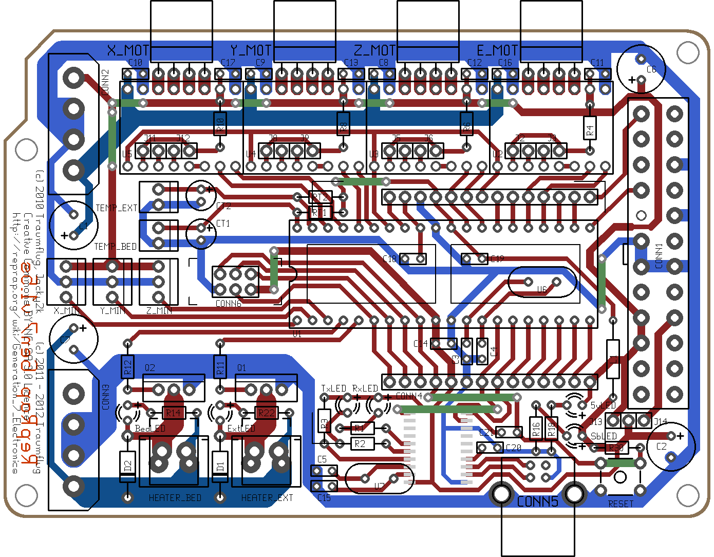
So, that's the full-featured Gen7 v1.5 in 115x79 mm.

Original outline is here for comparison purposes only. A couple of caveats:
1. Heater connectors are the screw terminal version only.
2. Endstop connector pins are mirrored, so signal is now 5V and 5V is now signal.
3. Axis (and extruder) connectors must be right angle or standar 4 pin header.
4. Extension Board is 14x11 pin size.
Schematics are the same (only 5V-SB LED and resistor interchanges their position to fit better in layout), no DRC violations, and there are only one more wire bridge. Some footprints need to be changed.
Quote
Traumflug
When I made that EB-footprint I'd have loved to have a crystal ball to look a bit into the future to see what it's used for.
I need one 'cause now is time for etching, testing, and if I'm lucky, using it. Cross your fingers

Take this opportunity to thank you for this awesome piece of hardware, and for letting us to play with it.
Edited 1 time(s). Last edit at 02/25/2013 09:40AM by xoan.
|
Re: Generation 7 Electronics Development February 26, 2013 04:02PM |
Registered: 13 years ago Posts: 7,616 |
Looks excellent, Xoan!
> 1. Heater connectors are the screw terminal version only.
Looks like that's easy to solve for those who prefer plugs.
> 2. Endstop connector pins are mirrored, so signal is now 5V and 5V is now signal.
Could be solved by turning them 180° ? Doesn't matter much if you do the cabling yourself, though.
> 3. Axis (and extruder) connectors must be right angle or standar 4 pin header.
To me it looks like they overlap with the Pololus, but I guess you know what you're doing.
Congratulations!
| Generation 7 Electronics | Teacup Firmware | RepRap DIY |
|
Re: Generation 7 Electronics Development February 26, 2013 10:06PM |
Registered: 11 years ago Posts: 64 |
Quote
Traumflug
Looks excellent, Xoan!
[...]
Congratulations!
Thanks, but most of this is entirely your work, not mine (I've only made some PCB layout tweaks

Quote
Traumflug
> 2. Endstop connector pins are mirrored, so signal is now 5V and 5V is now signal.
Could be solved by turning them 180° ? Doesn't matter much if you do the cabling yourself, though.
Yeah, in fact this can be changed when soldering. IMO, it's only the footprint and silkscreen convention to put connector pointing to the layout border.
Quote
Traumflug
> 3. Axis (and extruder) connectors must be right angle or standar 4 pin header.
To me it looks like they overlap with the Pololus, but I guess you know what you're doing.
I've made (actually I've tried to do) another footprint to the *-axis connectors. It's a right angle KK100 or something similar.
I've made some more changes to the heaters layout and now it is back to your original footprint to allow 3.96 connectors and 5.08 screw terminal. I will hope the Vcc path to LED resistor not to burn, so is there any correction or error I should consider to the actual (and final I guess) layout?

I had never used an electronics design application until now, but after these days, I can say that gEDA is an amazing software
|
Re: Generation 7 Electronics Development February 28, 2013 04:23PM |
Registered: 11 years ago Posts: 64 |
Hi again,
I believe this is my last message (in the main developer thread) related to refactoring Gen7Board-AVR layout to make it down to 120x80 mm PCB size.
I've working on USB area, and... VOILA! Original ExtensionBoard footprint is now back into the board, so except for the extruder and *-axis connectors, all the rest is fully compatible --in theory
I've made a fork of your GitHub repository and I've created a new branch to share the source files, but sorry, there are no commit history because I lost my .git directory during cleaning up
I've been playing with the gerber files and Visolate (great software) and I've found that outlines made by arcs are not supported. There is no problem, is just for to notice the issue.
Edited. Any feedback or suggestions would be really appreciated.
Edited 3 time(s). Last edit at 03/01/2013 02:52AM by xoan.
I believe this is my last message (in the main developer thread) related to refactoring Gen7Board-AVR layout to make it down to 120x80 mm PCB size.
I've working on USB area, and... VOILA! Original ExtensionBoard footprint is now back into the board, so except for the extruder and *-axis connectors, all the rest is fully compatible --in theory

I've made a fork of your GitHub repository and I've created a new branch to share the source files, but sorry, there are no commit history because I lost my .git directory during cleaning up
I've been playing with the gerber files and Visolate (great software) and I've found that outlines made by arcs are not supported. There is no problem, is just for to notice the issue.
Edited. Any feedback or suggestions would be really appreciated.
Edited 3 time(s). Last edit at 03/01/2013 02:52AM by xoan.
|
Re: Generation 7 Electronics Development March 01, 2013 08:11AM |
Registered: 13 years ago Posts: 7,616 |
Excellent work, @xoan!
Two things left:
- There has to be a distinction between the GND track going to the MOSFETs and the one going to the thermistor connectors. As they're currently drawn they likely connect to each other when using Visolate. Extending one of the nearby tracks to fill some of the room between both ends of the huge GND track should help.
- What's the purpose of all this (I'm just curious) ? Are there printers where a 100 mm wide PCB doesn't fit, but a 80 mm wide one does? And how how do the overlapping connectors fit there? Would a 80 mm x 140 mm board fit there, too?
Visolates lack of support for curved tracks is known & fixable & not yet fixed.
| Generation 7 Electronics | Teacup Firmware | RepRap DIY |
|
Re: Generation 7 Electronics Development March 01, 2013 08:57AM |
Registered: 11 years ago Posts: 64 |
Quote
Traumflug
There has to be a distinction between the GND track going to the MOSFETs and the one going to the thermistor connectors. As they're currently drawn they likely connect to each other when using Visolate. Extending one of the nearby tracks to fill some of the room between both ends of the huge GND track should help.
Yeah, I saw while looking into generated voronoi toolpath. I understood the bridge in the GND track instead in the 5V. Fixed this morning.
Quote
Traumflug
What's the purpose of all this (I'm just curious) ? Are there printers where a 100 mm wide PCB doesn't fit, but a 80 mm wide one does? And how how do the overlapping connectors fit there? Would a 80 mm x 140 mm board fit there, too?
I made one v1.4.1 and one v1.5 (still in assembly due the lack of 12MHz oscillator) by etching using a 100x160 mm PCB, and I thought that the board could be down to 120x80 mm (here in the local electronics store there are PCBs of this size), so taking the opportunity to learn some gEDA basics, I made this.
The filosophy behind the board attracts me (open, DIY, etc). My electronics knowledge is very, very poor but I've been planning to make an ExtensionBoard to support dual extruder in your board, so I believe this is a mandatory previous step (to be comfortable with the board design itself and also with the software tools to develop it)
Unless the above, there is no purpose, simply experiment, curiosity and enjoyment
Edited 1 time(s). Last edit at 03/01/2013 09:01AM by xoan.
|
Re: Generation 7 Electronics Development March 01, 2013 09:32AM |
Registered: 11 years ago Posts: 121 |
From a gen7 user perspective, I have been closely following Xoan's posts now.
I like the smaller layout:
- Same, my local supplier guillotines smaller sizes as stock. For Gen7 I have to wait while they guillotine boards
- Toner transfer. The average iron is smaller than the current Gen7. This means I cannot press the whole board in one go. Smaller boards are easier to iron onto copperclad.
- Mounting: again smaller they are, easier to hide in frame
Some gripes i have with both layouts still:
- ATX24 and 4 ways on different sides of board. So no matter how you try the thicker PSU cables has to ho over or under the PCB or other wires. If someone finds away to put all power circuitry to one side, wiring would be a dream
- mcp2200 reset. The reenumaration dance gets less exciting as time goes on
- reset switch. Behind USB socket = very difficult to reach in emergency or otherwise. Move it closer to board edge
Peter
|
Re: Generation 7 Electronics Development March 07, 2013 09:27AM |
Registered: 11 years ago Posts: 64 |
Quote
Rezer
If the USB is unplugged after that and plugged back in you have to power cycle the board, wait for the caps to discharge, and plug it back in. I'm assuming this is a side effect of powering the MCP2200 from the board instead of the usb port and not shoddy soldering on my part, but I'm less than 100% positive on that one. Is this expected behavior?
I just finished soldering a Gen7 v1.5 right now, and if I plug and unplug the board while PSU is connected, and plug it again, MCP2200 is properly reenumerated.
I'm using Arch Linux and this is the `dmesg' output:
[140023.076106] usb 2-1: new full-speed USB device number 15 using ohci_hcd
[140023.284716] cdc_acm 2-1:1.0: This device cannot do calls on its own. It is not a modem.
[140023.284759] cdc_acm 2-1:1.0: ttyACM0: USB ACM device
[140023.304424] hid-generic 0003:04D8:00DF.0010: hiddev0,hidraw3: USB HID v1.11 Device [Microchip Technology Inc. MCP2200 USB Serial Port Emulator] on usb-0000:00:03.0-1/input2
[140041.553843] usb 2-1: USB disconnect, device number 15
[140045.582772] usb 2-1: new full-speed USB device number 16 using ohci_hcd
[140045.791342] cdc_acm 2-1:1.0: This device cannot do calls on its own. It is not a modem.
[140045.791387] cdc_acm 2-1:1.0: ttyACM0: USB ACM device
[140045.811079] hid-generic 0003:04D8:00DF.0011: hiddev0,hidraw3: USB HID v1.11 Device [Microchip Technology Inc. MCP2200 USB Serial Port Emulator] on usb-0000:00:03.0-1/input2
Don't know if this is the expected or unexpected behaviour, but I think this is what the board should work.
Edited 1 time(s). Last edit at 03/07/2013 09:29AM by xoan.
|
Re: Generation 7 Electronics Development March 07, 2013 10:42AM |
Registered: 11 years ago Posts: 64 |
Quote
peter6960
- ATX24 and 4 ways on different sides of board. So no matter how you try the thicker PSU cables has to ho over or under the PCB or other wires. If someone finds away to put all power circuitry to one side, wiring would be a dream
Sure, but I believe a lot of rework would be required in order to achieve that. In the smaller PCB I've been doing I think that may be impossible.
Quote
peter6960
- mcp2200 reset. The reenumaration dance gets less exciting as time goes on
- reset switch. Behind USB socket = very difficult to reach in emergency or otherwise. Move it closer to board edge
I've no trouble with MCP2200 reenumeration so reset switch can be moved closer to the board edge but leaving unaccessible the USB5V output (see attached layout).
|
Re: Generation 7 Electronics Development March 08, 2013 02:37AM |
Registered: 12 years ago Posts: 39 |
xoan Wrote:
-------------------------------------------------------
> > If the USB is unplugged after that and plugged
> back in you have to power cycle the board, wait
> for the caps to discharge, and plug it back in.
> I'm assuming this is a side effect of powering the
> MCP2200 from the board instead of the usb port and
> not shoddy soldering on my part, but I'm less than
> 100% positive on that one. Is this expected
> behavior?
>
>
> I just finished soldering a Gen7 v1.5 right now,
> and if I plug and unplug the board while PSU is
> connected, and plug it again, MCP2200 is properly
> reenumerated.
>
> I'm using Arch Linux and this is the `dmesg'
> output:
>
>
> [140023.076106] usb 2-1: new full-speed USB device
> number 15 using ohci_hcd
> [140023.284716] cdc_acm 2-1:1.0: This device
> cannot do calls on its own. It is not a modem.
> [140023.284759] cdc_acm 2-1:1.0: ttyACM0: USB ACM
> device
> [140023.304424] hid-generic 0003:04D8:00DF.0010:
> hiddev0,hidraw3: USB HID v1.11 Device on
> usb-0000:00:03.0-1/input2
> [140041.553843] usb 2-1: USB disconnect, device
> number 15
> [140045.582772] usb 2-1: new full-speed USB device
> number 16 using ohci_hcd
> [140045.791342] cdc_acm 2-1:1.0: This device
> cannot do calls on its own. It is not a modem.
> [140045.791387] cdc_acm 2-1:1.0: ttyACM0: USB ACM
> device
> [140045.811079] hid-generic 0003:04D8:00DF.0011:
> hiddev0,hidraw3: USB HID v1.11 Device on
> usb-0000:00:03.0-1/input2
>
>
> Don't know if this is the expected or unexpected
> behaviour, but I think this is what the board
> should work.
Maybe it works better with linux, I'm on win 7 64 bit and it seems to be a bit of a crapshoot...sometimes the second, third, etc time plugging in works as expected, but frequently it spits out the "unrecognized device" error and the only remedy is to power cycle the entire board.
Edited 2 time(s). Last edit at 03/08/2013 02:38AM by Rezer.


Sorry, only registered users may post in this forum.