I designed a new low cost high accuracy version of the Mini Kossel, zero backlash or slop, perfect prints!
Posted by Milton
|
I designed a new low cost high accuracy version of the Mini Kossel, zero backlash or slop, perfect prints! September 10, 2016 12:59AM |
Registered: 7 years ago Posts: 59 |
You can download the files and make your own here:
http://www.thingiverse.com/thing:1699922
Totally compatible with Mini Kossel, easy upgrade to try out. $5 for an entire set of carriages! Alpha prototype printing like a dream with a Duet, Mini Hotend, Mini IR Sensor.
I traded buying expensive linear motion parts for buying an expensive controller instead, and designed a Delta specific super light weight linear motion system, all moving parts are selected for low weight or redesigned to be low weight.
Results:
Singing dragon, issues still with Bowden extruder which is totally new to me, but accuracy is all there.
100mmx120mm Duet case, perfect edges!
My image links seem to fail (tried google photos and imgur, both wont show an image just an error), same images attached plus a few more. different kinds of prints, art and structural parts, curves and straight edges.
It's all explained a bit better on the Thingiverse post. Hoping someone making a mini kossel tries my linear motion design, it is honestly very good at least for the initial testing, longevity may be an issue, for $5 total and a buck or two replacing bushings after rotating them several times, it may be very viable to achieve high accuracy delta printer.
http://www.thingiverse.com/thing:1699922
Totally compatible with Mini Kossel, easy upgrade to try out. $5 for an entire set of carriages! Alpha prototype printing like a dream with a Duet, Mini Hotend, Mini IR Sensor.
I traded buying expensive linear motion parts for buying an expensive controller instead, and designed a Delta specific super light weight linear motion system, all moving parts are selected for low weight or redesigned to be low weight.
Results:
Singing dragon, issues still with Bowden extruder which is totally new to me, but accuracy is all there.

100mmx120mm Duet case, perfect edges!

My image links seem to fail (tried google photos and imgur, both wont show an image just an error), same images attached plus a few more. different kinds of prints, art and structural parts, curves and straight edges.
It's all explained a bit better on the Thingiverse post. Hoping someone making a mini kossel tries my linear motion design, it is honestly very good at least for the initial testing, longevity may be an issue, for $5 total and a buck or two replacing bushings after rotating them several times, it may be very viable to achieve high accuracy delta printer.
|
Re: I designed a new low cost high accuracy version of the Mini Kossel, zero backlash or slop, perfect prints! September 10, 2016 03:06AM |
Registered: 8 years ago Posts: 3,525 |
Some good ideas there, certainly more stable corners, and carriages. What material are the bushings for the carriages?
Ah I see now I've read a bit further on. Nice.
Edited 1 time(s). Last edit at 09/10/2016 03:07AM by DjDemonD.
Simon Khoury
Co-founder of [www.precisionpiezo.co.uk] Accurate, repeatable, versatile Z-Probes
Published:Inventions
Ah I see now I've read a bit further on. Nice.
Edited 1 time(s). Last edit at 09/10/2016 03:07AM by DjDemonD.
Simon Khoury
Co-founder of [www.precisionpiezo.co.uk] Accurate, repeatable, versatile Z-Probes
Published:Inventions
|
Re: I designed a new low cost high accuracy version of the Mini Kossel, zero backlash or slop, perfect prints! September 12, 2016 02:33AM |
Registered: 8 years ago Posts: 3,525 |
Regarding bowden extruder I'd ditch it and consider a flying extruder or flexible drive (flex3drive or the new Zesty). I think bowden is a workaround rather than a solution, there are just too many compromises in it for me.
If I might ask, on your delta carriages why not change the position of the fixing points for the traxxas joints? So long as they keep the same spacing they will work. What I have in mind is moving them lower and placing them on the side of the carriage. This potentially makes for less of a lever, there would be less play, and a smaller simpler part. I've been looking at my kossel mini and I think the only reason they are where they are is to accommodate the two carriages in the original design.
Simon Khoury
Co-founder of [www.precisionpiezo.co.uk] Accurate, repeatable, versatile Z-Probes
Published:Inventions
|
Re: I designed a new low cost high accuracy version of the Mini Kossel, zero backlash or slop, perfect prints! September 12, 2016 05:22AM |
Registered: 7 years ago Posts: 59 |
The position chosen is designed to maximize the build area and is not a lever as the belts are nearly in line with the axis of the ball joint. Offsetting them horizontally creates a lever not vertically. I have offset them slightly towards center as the radius only affects accuracy as far as the setting, you get a larger diameter buildable area by allowing the arms to clear the belts, you can have the effector very close to the belts this way and still have a round build area.
There is no play, even with entirely PLA printed parts.
Literally, not kidding, zero play, perfect accuracy at 60mm/s .2 layer.
I could not be happier with the system I designed. It is totally effective at accurate linear motion. Did you look at the latest print results?
I hope you try them, you will be very happy, with prints that are as precise as your firmware settings. The linear motion is not borrowed from another industry it is designed specifically and carefully for 3d printing needs to have zero play at all and place the nozzle tip precisely.
The PLA material I am using for prototypes is probably flexing slightly, I can't see it in the prints yet though, I am shocked at the accuracy to be honest. I suspected it would work or I would not have taken the large amount of time to design it. 2 months of design for a project I am locked in on means thinking and prototyping for the entire day, for 2 months. 14-18 hour design sessions 7 days a week for 2 months.
I wrote some stuff about past experiences and education, but deleted it, it just doesn't matter, you can try them or not, doubt them if you want, I am not going to spend time coxing others to try them I just don't even know how. I can design stuff that works very well, dealing with people... yeah no, I would rather just check the batteries in the calipers.
Edit: K sorry got butt hurt about the cantilever thing, just a little bit. I know I should try to explain it better if I want others to try it, I'm just tired from the design process and need to recharge. Sorry.
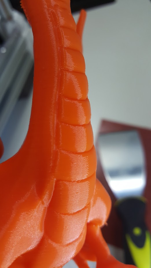
here are pics of good and bad prints, full disclosure of the capabilities and possible issues.
Dragon turned out great, extrusion issues from new extruder/1st bowden/new slicer but no complaints about accuracy. No complaints about accuracy with $2 linear motion... would you complain with SS rails?
For my first DIY printer and experimental sliding delrin bushings, not bad eh? What linear motion does better? I will buy it to have that, if it exists. Honestly I will I did this project accepting that if I found it lacking I would just buy good rails and carriages. Still probably will to try them and compare, but I am not ever taking this printer apart I will make another, it is to good a design tool for making excellent prints.
100mm or so of straight clean surface. without any gaps it makes great walls of any shape curved or rectilinear or whatever, as long as it doesn't have to infill or reverse to much...
so some bad prints...
this has a grid of air vent 3mm holes, I get all kinds of trouble on both my printers with prints like this. goes away with lower speeds of course. combination of corners lifting and rapid infill on narrow but not narrow enough for no infill sections. this is 2.5mm walls and on thinner with no infilling it doesn't do this (like the orange box nearly as big).
more artifacts from infilling walls but pretty good surface quality otherwise, .2 at 60mm/s outer wall 50% speed.
I am sure there are many things to improve. I appreciate all suggestions, or I should and my better self does.
The ball joint location I will think about but I like it where it is for the increased height and the tucked away look when they are homed and within a few mm of the pulleys. But it is worth considering I will keep an eye on how they are loading. I get that you mean the can be a cantilever for the arm motion, my arms are smooth moving and exactly the same length I have not had any issues. I would not move them to overcome bad arms, I would fix the arms. I could be wrong but that is my current thinking as far as Delta motion accuracy. Arms must be prefect or taken apart and made perfect, or it's just not going to work right.
Edited 1 time(s). Last edit at 09/12/2016 06:21AM by Milton.
There is no play, even with entirely PLA printed parts.
Literally, not kidding, zero play, perfect accuracy at 60mm/s .2 layer.
I could not be happier with the system I designed. It is totally effective at accurate linear motion. Did you look at the latest print results?
I hope you try them, you will be very happy, with prints that are as precise as your firmware settings. The linear motion is not borrowed from another industry it is designed specifically and carefully for 3d printing needs to have zero play at all and place the nozzle tip precisely.
The PLA material I am using for prototypes is probably flexing slightly, I can't see it in the prints yet though, I am shocked at the accuracy to be honest. I suspected it would work or I would not have taken the large amount of time to design it. 2 months of design for a project I am locked in on means thinking and prototyping for the entire day, for 2 months. 14-18 hour design sessions 7 days a week for 2 months.
I wrote some stuff about past experiences and education, but deleted it, it just doesn't matter, you can try them or not, doubt them if you want, I am not going to spend time coxing others to try them I just don't even know how. I can design stuff that works very well, dealing with people... yeah no, I would rather just check the batteries in the calipers.
Edit: K sorry got butt hurt about the cantilever thing, just a little bit. I know I should try to explain it better if I want others to try it, I'm just tired from the design process and need to recharge. Sorry.
here are pics of good and bad prints, full disclosure of the capabilities and possible issues.

Dragon turned out great, extrusion issues from new extruder/1st bowden/new slicer but no complaints about accuracy. No complaints about accuracy with $2 linear motion... would you complain with SS rails?

For my first DIY printer and experimental sliding delrin bushings, not bad eh? What linear motion does better? I will buy it to have that, if it exists. Honestly I will I did this project accepting that if I found it lacking I would just buy good rails and carriages. Still probably will to try them and compare, but I am not ever taking this printer apart I will make another, it is to good a design tool for making excellent prints.

100mm or so of straight clean surface. without any gaps it makes great walls of any shape curved or rectilinear or whatever, as long as it doesn't have to infill or reverse to much...
so some bad prints...


this has a grid of air vent 3mm holes, I get all kinds of trouble on both my printers with prints like this. goes away with lower speeds of course. combination of corners lifting and rapid infill on narrow but not narrow enough for no infill sections. this is 2.5mm walls and on thinner with no infilling it doesn't do this (like the orange box nearly as big).

more artifacts from infilling walls but pretty good surface quality otherwise, .2 at 60mm/s outer wall 50% speed.
I am sure there are many things to improve. I appreciate all suggestions, or I should and my better self does.
The ball joint location I will think about but I like it where it is for the increased height and the tucked away look when they are homed and within a few mm of the pulleys. But it is worth considering I will keep an eye on how they are loading. I get that you mean the can be a cantilever for the arm motion, my arms are smooth moving and exactly the same length I have not had any issues. I would not move them to overcome bad arms, I would fix the arms. I could be wrong but that is my current thinking as far as Delta motion accuracy. Arms must be prefect or taken apart and made perfect, or it's just not going to work right.
Edited 1 time(s). Last edit at 09/12/2016 06:21AM by Milton.
|
Re: I designed a new low cost high accuracy version of the Mini Kossel, zero backlash or slop, perfect prints! September 12, 2016 05:34AM |
Registered: 8 years ago Posts: 3,525 |
They look good to me, my roller carriages on my mini are getting a bit old, I'd love to try these. I'm a bit busy with the new build but they're on the list. Do you think the optimum bushing will be delrin?
Regarding the position for the rod mounts on the carriages surely the centre of rotation is between the belt fixings and the two sets of bushings, so mounting the rods within that volume generates the least play, uses the least plastic etc... I accept it would have an effect on build area. Its just a thought.
Seriously try the flying extruder when I did I noticed a massive jump in print quality coming from bowden. See the flying extruder mod thread for some images. Couple that with your zero play carriages and the print quality will be off the scale good.
I like your idea it's been done extremely well and it would be much less costly than hiwin rails.
Simon Khoury
Co-founder of [www.precisionpiezo.co.uk] Accurate, repeatable, versatile Z-Probes
Published:Inventions
|
Re: I designed a new low cost high accuracy version of the Mini Kossel, zero backlash or slop, perfect prints! September 12, 2016 06:32AM |
Registered: 7 years ago Posts: 59 |
thanks!
I totally want to try a flying extruder! I am totally worried that the design is not capable of supporting that weight!
It is designed from a 'light to remove inertia for precision' perspective and I think anything like a nema stepper, even a 14, on the carriages would compromise that enormously, but I should try, to see what happens and know versus speculate.
I have a concept for a wire pulley inside the belt. a wire or strong filament, kevlar or something, on spools just inside the pulley and stepper gear driving a second wireline 'belt' that a flying extruder is on. no inertia loading on carriages, only on the stepper. I am using Zyltech 84oz. 48mm 17's. only $12 each on Amazon and seem to be an epic deal. precise, I can touch them after 9 hours printing, barely but I can keep a finger on them and not be burned just uncomfortable till adjusted like a really hot hot tub! HOT HOT TUB! DID I JUST TYPE THAT? WTF? It is way to late! Gnight have a great week!
|
Re: I designed a new low cost high accuracy version of the Mini Kossel, zero backlash or slop, perfect prints! September 12, 2016 09:13PM |
Registered: 7 years ago Posts: 59 |
sorry to answer specificly 'best bushing' I had delrin from another project in the required size and it works exceptionally, but PTFE solid extrusion may be better. It is not tested but many have suggested it and it seems reasonable, only trade off is the durometer of the material is lower. I plan on experimenting with solid tubular metal cores, cut sections of tubing as reinforcement to stabilize compression, if PTFE needs it, and it may be that the denser and less compressible plastics balance friction better by retaining a smaller surface area. 8 contact points provides exceptional stability but friction and stiction will increase if they spread out, they don't need to nor should they, staying aligned requires good resistance. I just can't say for sure without testing them quite a lot, which I will be doing as I have picked up sponsors from the base component suppliers to continue the design development! 
Will order PTFE rod in the next 4 days, sourcing supplier ASAP. Definitive answers soon!
Will order PTFE rod in the next 4 days, sourcing supplier ASAP. Definitive answers soon!
|
Re: I designed a new low cost high accuracy version of the Mini Kossel, zero backlash or slop, perfect prints! September 12, 2016 09:48PM |
Registered: 9 years ago Posts: 483 |
PTFE machines nicely, so you shouldn't have any trouble machining a bushing. It will cold flow over time, so constraining it in a metal tube would be best. In a 3d printer, there may not be enough force on the PTFE to cause it to flow very much. In another non-3d printer project I used cast polyurethane resin to constrain the PTFE tubing. It's been working well for several years.
McMaster-Carr has PTFE rods, but may not ship outside USA.
McMaster-Carr has PTFE rods, but may not ship outside USA.
|
Re: I designed a new low cost high accuracy version of the Mini Kossel, zero backlash or slop, perfect prints! September 13, 2016 12:20AM |
Registered: 7 years ago Posts: 59 |
cool suggestion and observation of long term use.
I phrased what I was saying badly, but I think you got it. Solid OR tubular cores of a firm material like brass tube inserted into PTFE TUBING, instead of solid extruded PTFE rod. everyone has 4mm OD PTFE I am thinking use the smaller outer channels of OpenBeam 1515 with bushings made from that and use a 2mm solid or tube metal inner core to stabilize the amount of compression to wall material, and remove the issue of deformation from round due to the hollow core of the PTFE tubing.
this might be an even cheaper even more effective bushing.
there, much better explanation, whew!
I am bad at full explanations sometimes, skip over details in haste to get point across
Edited 3 time(s). Last edit at 09/13/2016 12:24AM by Milton.
|
Re: I designed a new low cost high accuracy version of the Mini Kossel, zero backlash or slop, perfect prints! September 13, 2016 02:40AM |
Registered: 8 years ago Posts: 13 |
I have tried using PTFE tubes (4mm OD with filament inside) using 8 of them in contact with the alu extrusion. And i don't think it will work, or last long.
In the first few hours, it prints nicely, no slop at all. After a few prints I found out that the extrusion are shaving the PTFE tubes and leaving shavings on the extrusion.
In the first few hours, it prints nicely, no slop at all. After a few prints I found out that the extrusion are shaving the PTFE tubes and leaving shavings on the extrusion.
|
Re: I designed a new low cost high accuracy version of the Mini Kossel, zero backlash or slop, perfect prints! September 16, 2016 12:30AM |
Registered: 7 years ago Posts: 4 |
|
Re: I designed a new low cost high accuracy version of the Mini Kossel, zero backlash or slop, perfect prints! September 16, 2016 05:17PM |
Registered: 7 years ago Posts: 59 |
It think it would but it would need redesigning for the width of the extrusion. Also the extrusion needs to be very smooth, high quality surface finish of extrusions ment for commercial display or exterior viewable design qualities, rough framing extrusions without excellent surface quality will probably not work without prep of the surface, which I have not done.
Designing the pre-compression load into the print is tedious, takes a lot of print test adjust and reprint. Feel free to give it a go, it took me a month of industrial design to come up with the specific arrangement but a redesign for a different width you can use the basic layout and just make prototypes of the C shaped bushing holder mount, your own version for 2020, keep the spacing of the screws and the carriage arm mount will work with the new part.
One thing though, the 1:2 ratio used for spacing bushings from a leverage cantilevered point needs to be taken into account for the wider extrusion the spacing should be slightly more than 55mm bushing to bushing as the belt is going to be more than 22mm offset due to the increased diagonal distance.
Corners will just not work, totally designed for 1515 they would need to be redesigned completely for the spacing of everything.
I recommend 1515 for this particular set of parts as they work, and it's inexpensive for a set of OpenBeam which I know have good enough surface quality. I would not do it with a rough surfaced extrusion without buffing and polishing or even milling the surface, but that will change it dimensionally and be really hard to make each the same. Too much hassle since a full kit of OpenBeam in silver for a mini kossel, kit I used, is only $33 which is like a darn good deal for non printer specific good framing parts that can be used for any project (versus a dedicated drilled and taped metal part that only fits in one machine design).
Extrusion should have a rounded lip on the T slot, be a good surface quality and may need a light smoothing with 2000 grit or higher sandpaper on the lip of the extrusion. I had to smooth one little divot/nick in the edge of one T slot channel (that I created when unboxing and admiring them without enough care). Easy to put dings in the soft aluminum so I would use newer extrusions versus old ones, or check them carefully.
making the T slot into the rail, they do need to be new straight and clean surface extrusions ideally, older ones may need a lot of prep or just be too roughed up from use to work. Aluminum is soft like that.
Sorry, only registered users may post in this forum.