How critical is the accuarcy of the different arm lengths ?
Posted by ianmcmill
|
How critical is the accuarcy of the different arm lengths ? August 28, 2014 05:43AM |
Registered: 10 years ago Posts: 153 |
Hi
while building my Rostock Mini (from [www.thingiverse.com]) I needed to glue the carbon rods to the Traxxas U-Joints.
After glueing them in it raised a question.
How critical is the accuarcy of the different arm lengths ?
How far is it possible to adjust the length of each arm pair by the endstop-screw ?
Is it possible to calibrate or set an offset anywhere, anyhow to compensate varying carbon arm length ?
The 6 arms are:
19,3 cm
19,2 cm
19,25 cm
19,21 cm
19,2 cm
19,2 cm
+/-1 mm (measured with double meter stick)
|
Re: How critical is the accuarcy of the different arm lengths ? August 28, 2014 07:29AM |
Registered: 9 years ago Posts: 45 |
First, I would advice you to use a large caliper, and if you don't have such a tool, a simple tape measure.Quote
ianmcmill
+/-1 mm (measured with double meter stick)
Second, if you look to several calibration guidelines, you'll see that they're considering the average of the rod length. Here, your length error is about 1 mm and I think unmounting your rods in order to adjust them will give you some improvements on your future prints. To unglue them, I don't see many solutions. Maybe some solvant?
|
Re: How critical is the accuarcy of the different arm lengths ? August 28, 2014 07:33AM |
Registered: 10 years ago Posts: 153 |
My calipers won't measure this far. 153mm at most. A simple tape measuer won't be more accurate than this yardstick/zollstock.
I epoxied the u-joints. So it's easier to order new Traxxas u-joints and carbon rods.
I'll read the calibration articles for futher clarification. Thank you thib88 for pointing me in the right direction.
I epoxied the u-joints. So it's easier to order new Traxxas u-joints and carbon rods.
I'll read the calibration articles for futher clarification. Thank you thib88 for pointing me in the right direction.
|
Re: How critical is the accuarcy of the different arm lengths ? August 28, 2014 08:02AM |
Registered: 9 years ago Posts: 79 |
It is extremely critical. If they are not exact, the machine will suffer from mechanical effects. My first build had this problem and if you moved the effector/platform near the tower of the arms that were shorter, you would see the effector start to tilt up. If you moved it away, it would tilt downwards. So it effects how flat the printer will print and with changing angles like that, the prints will suffer from incorrect measurements and other print issues that will be unable to fix in the firmware unless corrected.
Along with the incorrect measurements, you will have mechanical binding. I noticed, when I took the carriage, arms, and effector out of the machine that the arm pairs that were equally matched would move in a perfect circle if you grabbed he carriage and moved in a circular motion; however, the arms that had mismatched pairs would bind in some area of the circle and would travel in a flat pattern-unable to complete the circle at some quadrant of the circle.
To my knowledge you do not adjust the endstops to account for incorrect delta diagonal rod dimensions, but to adjust z height if you have an endstop that is lower or higher than the other two. For instance, if the X and Y tower readings during the tower calibration are at a Z height of 0, but the Z tower is at -4 (nozzle pushing extremely hard against the bed) or above the bed at a Z height of +2. In this situation to account for the mismatch, you would reduce or increase the Z height for that tower alone with a M666 code (e.g. M666 Z-4 in the case of -4 reading or M666 Z+2 for +2). This would effectively back off or raise the carriage closer or farther from the endstop on that tower to try to account for the difference in heights between the endstops, so that when you go to G1 X0 Y0 Z0 you will be at Z 0 at all areas.
You can however adjust for a tower being located either closer or further away from the center, but to my knowledge there are no delta diagonal rod corrections in the firmware.
Your numbers [(3) 192.0mm, (2) 192.5mm, and (1) 193.0mm] are very close to your target of 192.0 mm, but the longer rods will cause the effects that I mentioned above. It will be very apparent if you match the 193mm rod with a 192mm rod. That paring will have mechanical binding.
What type of glue did you use to bond the carbon to the traxxas ball joints? Can you remove it? On my traxxas rods, before I epoxy them I place an m4 screw in the traxxas rod end so that if I ever need to lengthen a rod, I can just screw it out. It also helps in saving the end link if I need to replace the carbon. A jig is also critical when gluing the rods. I cut the rods together and epoxy them to the joints at the same time in a jig so that everyone is exact. If you are unable to adjust those three rods, you may want to remake to rods: you can try to cut off one traxxas end link and try to adjust by placing a m4 set screw in the carbon rod an then screwing the the traxxas end link until you reach 192mm.
PS I'm a composites/carbon fiber expert by profession, do not use solvent as you are more likely to erode the resin (polyester of epoxy) that is keeping the carbon fabric together. You can use heat, to a certain degree (200 F.), but the best option is to cut them off (use protection-carbon dust is dangerous if inhaled).
Edited 3 time(s). Last edit at 08/28/2014 10:51AM by Wildcard.
|
Re: How critical is the accuarcy of the different arm lengths ? August 28, 2014 10:36AM |
Registered: 10 years ago Posts: 153 |
Very comprehensive explanation ! Thank you !
The method with the screw is a really good. I have seen this in the Rostock Mini Pro build.
I used 2 component glue. Breaking stress at approx. 1900N/cm² as the manual says. Cutting the rods at the ball joints and attaching a set screw would be best practise but on the other hand I could get new ball joints and carbon rods with the same inner diameter. I think the ones I have right now differ (carbon rods ID is 2.5 mm, ball joints are 3.5mm). So I could use a m3 set screw to connect the ball joints and the carbon rods.
The outcome would look nicer than the cut black plastic pieces from the ball joints
Thanks Wildcard !
PS.:
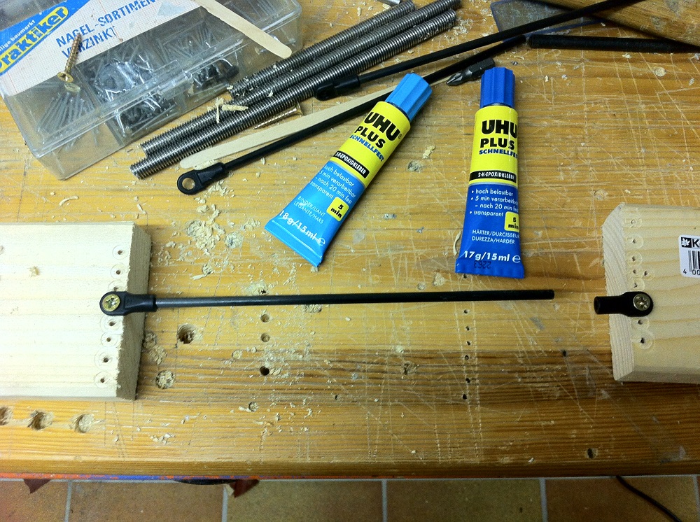
To get the ball joints perfectly parallel on both ends of the rod I did following (see attachment)
Edited 2 time(s). Last edit at 08/28/2014 10:51AM by ianmcmill.
The method with the screw is a really good. I have seen this in the Rostock Mini Pro build.
I used 2 component glue. Breaking stress at approx. 1900N/cm² as the manual says. Cutting the rods at the ball joints and attaching a set screw would be best practise but on the other hand I could get new ball joints and carbon rods with the same inner diameter. I think the ones I have right now differ (carbon rods ID is 2.5 mm, ball joints are 3.5mm). So I could use a m3 set screw to connect the ball joints and the carbon rods.
The outcome would look nicer than the cut black plastic pieces from the ball joints
Thanks Wildcard !
PS.:
To get the ball joints perfectly parallel on both ends of the rod I did following (see attachment)
Edited 2 time(s). Last edit at 08/28/2014 10:51AM by ianmcmill.
|
Re: How critical is the accuarcy of the different arm lengths ? August 28, 2014 11:03AM |
Registered: 9 years ago Posts: 79 |
Glad I could help! Good, you already have a jig. Magnets also work and are great for holding the metal traxxas ends to the jig, and they allow for small precision changes. A pack of N35s. The best adhesive for carbon is 24 hour 2 part epoxy. A slow epoxy will come with a working time of 45 minutes, so you have time to adjust and readjust until you know you have the correct dimensions. You may want to add in two blocks that are perpendicular to the rods and touches all of the traxxas joints at their outermost region, one on each side of the rods. That way you know that they are all held Parallel, and it also serves as another method of making sure that they are equal.
|
Re: How critical is the accuarcy of the different arm lengths ? August 28, 2014 11:15AM |
Registered: 10 years ago Posts: 469 |
honestly if you get a piece of wood that is a few cm longer than the rods your trying to build you can make them identical.
in the wood drill two holes precisely measured and use some screws or two drill bits to hold the length, then glue them one by one. You will get a consistent rod length that way. I am about to do this again as I used solid alu rods last time as I could not wait for the cf tubes. Now I have to order new traxxass rod ends or some other rod end.
My Personal Blog. Build blog.
[engineerd3d.ddns.net]
Modicum V1 sold on e-bay user jaguarking11
|
Re: How critical is the accuarcy of the different arm lengths ? August 28, 2014 11:37AM |
Registered: 10 years ago Posts: 153 |
Another method would be to print out a jig with attachments for the ball joints with exact distances for the carbon rods. If I think about it, the carbon rods can even be shorter (by 1-2 mm) but because of the fixed traxxas ball joint attachments you can simply glue in the rods without further hassle.
|
Re: How critical is the accuarcy of the different arm lengths ? August 28, 2014 06:02PM |
Registered: 10 years ago Posts: 732 |
The best approach is to use right threaded screw on one side of a rod and left threaded screw on the other. Glue the screws to the rod. Then screw the ball joints at the screws. This allows you to adjust the rod length precisely. Otherwise (if you would use the same threads on both sides of a rod) you can set the rod length with the precision of pitch/2 only (that means 0.25 mm for M3, not very good).
Marlin firmware can be easily updated to support different rod length for each tower (Repetier even supports this out of the box). But rods connecting to the same tower must be the same.
Marlin firmware can be easily updated to support different rod length for each tower (Repetier even supports this out of the box). But rods connecting to the same tower must be the same.
|
Re: How critical is the accuarcy of the different arm lengths ? August 28, 2014 10:40PM |
Registered: 9 years ago Posts: 56 |
Quote
hercek
Marlin firmware can be easily updated to support different rod length for each tower (Repetier even supports this out of the box). But rods connecting to the same tower must be the same.
That's how I did it, paired the same lenth rods together and adjusted one tower setting for that extra mm (DELTA_DIAGONAL_CORRECTION_C 1, default setting is 0).
Quote
Wildcard
do not use solvent as you are more likely to erode the resin (polyester of epoxy) that is keeping the carbon fabric together. You can use heat, to a certain degree (200 F.), but the best option is to cut them off
The first time I didn't use a jig and rods came out all different length so I heated the printer head at around 80C and used it to heat and pull away traxxas screws from the rods, cleaned and glued them together again on a jig.
All about delta 3d printers in one place [www.deltarap.org]
|
Re: How critical is the accuarcy of the different arm lengths ? August 29, 2014 10:02AM |
Registered: 9 years ago Posts: 79 |
Quote
hercek
The best approach is to use right threaded screw on one side of a rod and left threaded screw on the other. Glue the screws to the rod. Then screw the ball joints at the screws. This allows you to adjust the rod length precisely. Otherwise (if you would use the same threads on both sides of a rod) you can set the rod length with the precision of pitch/2 only (that means 0.25 mm for M3, not very good).
Marlin firmware can be easily updated to support different rod length for each tower (Repetier even supports this out of the box). But rods connecting to the same tower must be the same.
I use the m4 set screws as a method to recover the traxxas arms if I ever need to replace the carbon rods. It also helps to align the traxxas with the tube. When replacing arms, I use a razor and cut a slit on both sides on the end of the rod, and the traxxas end with it's fully epoxy covered set screw just slides out. Since the set screw has cured epoxy on it which is of the correct inner diameter of the rod, I can re-epoxy it and just slide it into a new rod. When I remade my rods a few weeks ago, I fixed one end by letting the epoxy cure on one side. Then the other side I adjusted the length via pulling the traxxas rod with inset out until the correct length was reached.
DinoK
Heat can always work to remove glue, most epoxies will start to get weak at around 500 degrees, unless they are high temp. Your experience is very similar to my first attempt. I had a jig that only fit one rod at a time, and it had a flaw that would allow different lengths. When curing I could not see that some of the rods had shifted during curing and had become shorter or longer. The next time around, the carbon was cut together in my bandsaw, and they were epoxied and cured together. One thing that I would recommend is filling the rod to make it rigid. I bought some dessert sticks that were the correct diameter for my tubes, coated them with epoxy and slid them into the tubes when I was remaking them a few weeks ago. The rods are now a sandwich panel and will benefit from the I-beam effect. I recommend this step to anyone.
Sorry, only registered users may post in this forum.