LISA Simpson
Posted by nicholas.seward
|
Re: LISA Simpson December 16, 2013 12:55PM |
Registered: 10 years ago Posts: 1,433 |
rather than continue on with the edits...
I did some searching for motors. My guess was I'd have to ship things in from China and that would take a while. I decided on some ~ 400 oz-in NEMA-23's. Turns out I found a set of 3 with drivers and a US ship location.
[www.ebay.com]
Usual disclaimer – I know nothing about the seller. The risk seemed reasonable to me. It may not be to others.
I figure I’ll run them on 48V. Not sure which supply to use quite yet. The Mean Well SE-600-48 looks about right.
I’m still spinning around a bit on the dimensions of the printer. I think it’s going to come out a bit bigger in X and Y than I thought originally. I made a simple math goof when I did the X and Y calculations in my head. I’m up to something closer to 30” for the spacing on the lead screws with 48” long screws. I’ve got 4” solid wall (not foam) PVC penciled in for the outer supports. I’m bouncing around on the aluminum for the arms. Something like 1.5” x 2” 1/8” wall 6061-T6 would be about 2 pounds for each arm. 2” x 3” would get it to 1.5X that in 1/8”. It would double with ¼” wall. The ¼” stuff starts to get a bit expensive.
|
Re: LISA Simpson December 16, 2013 01:21PM |
Registered: 10 years ago Posts: 1,381 |
|
Re: LISA Simpson December 16, 2013 01:49PM |
Registered: 12 years ago Posts: 85 |
Could you use threaded rods and threaded-on arm effectors to allow for easier tweaking or extending of arm lengths? Maybe two threaded rods in parallel like the bones in your forearm? Would give us something to do with all of those old Mendel Prusa rods lying around..
Something like that could make it easier to bootstrap a 1m LISA.
Thread rods for arms also makes me think that maybe you could design threaded arms where the 'shoulder' is able to extend outside of the build area (like chopsticks), to maximize build area at top/bottom. I think this could be done without additional motors if you could tie the motion of the lead screw rotation through a gear reduction to the threading of an arm and make it all linear? Or maybe I should just finish my coffee..
Edited 2 time(s). Last edit at 12/16/2013 01:54PM by jason.fisher.
|
Re: LISA Simpson December 16, 2013 02:00PM |
Registered: 10 years ago Posts: 1,433 |
Quote
A2
The stepper motors look sweet!
Add says round shaft, does that mean there is not a flat on the shaft?
Will they work with the Mega: 4.2A?
Fiberglass tubes softening at 140 F doesn't sound good.
I like the idea of using aluminum for the arms, price looks good, got a link?
The motors I decided on need external drivers. That's what drove me to the package I bought. The dirvers will do the 4.2A / 48V stuff and opto-isolate the Mega / Ramps combo. That way strange ground bounce issues in the motor world are less likely to crash the Mega.
I looked at several online metal outfits for the aluminum tube and they all had prices in the same ballpark. I'd like to get some confirmation that a hollow core rectangular tube is likley to be stiff enough for the application. If need be, I still have the "mill it out of a solid bar" approach to fall back on. There is indeed a lot of torque going to be flying round between the rods via the center of this beast.
My objective is to double the build volume of the standard design. I know I should have worked that out and stated it earlier. More or less I'm headed for something > 400mm dia and > 500 mm tall. If that drives me to 5' screws, so be it. They will either be 4 or 5 feet since it's all sold by the whole foot.
---------------
I just picked up on the move to ConceptForge for some of this ... somehow I missed that point earlier.
Edited 1 time(s). Last edit at 12/16/2013 02:01PM by uncle_bob.
|
Re: LISA Simpson December 16, 2013 02:31PM |
Registered: 11 years ago Posts: 979 |
@uncle_bob: With 400mm diameter by 500mm tall build volume you get 2^3=8 times the volume. Scaling is easy for this situation. Just double everything from my design. 4' screws will get you almost exactly that volume. 5' screws using the same screw spacing could get you 400mm diameter by 800mm tall. (Any extra length you add to the screw goes directly onto the print volume if you keep the screw spacing the same.)
|
Re: LISA Simpson December 16, 2013 02:39PM |
Registered: 10 years ago Posts: 1,433 |
Ok, that's pretty much what I had guessed. I've been wrong before....
Still pondering on what size aluminum rectangular tube to use for the arms.... or even if it's a good matterial to use at all.
---------------
Forgot earlier ... the motor shafts are round (no flat) as far as I know. That will make clamping to them a bit more exciting.
--------------
Looks like there is a gotcha on the 1" screws. You can't get the "cheap" nuts. Back to the 3/4" Hi-Lead at 0.5 tpi
Edited 2 time(s). Last edit at 12/16/2013 03:54PM by uncle_bob.
|
Re: LISA Simpson December 16, 2013 06:29PM |
Registered: 10 years ago Posts: 1,381 |
|
Re: LISA Simpson December 16, 2013 06:33PM |
Registered: 10 years ago Posts: 1,433 |
|
Re: LISA Simpson December 16, 2013 08:10PM |
Registered: 10 years ago Posts: 1,381 |
@uncle_bob
I don't think you have anything to worry about.
Review the Lisa video:
[www.youtube.com]
A negligible load is being applied to the arm via the screw rotating, and the nut moving up and down.
The arm has virtually a stress free ride.
A small bending moment will come from a weight on the end effector.
Do you plan to hang some thing really heavy off the end effector?
I was thinking that you might be mounting some thing like a 1/2" router.
In that case I'm more concerned with dampening the vibrations, and the joints being tight.
Filling the hollow arms with lead shot would be good for vibration dampening.
"Total energy transfer", dead blow hammers are a good example of this.
6061 aluminum, 1.5" x 3" with 1/8" wall tube is going to work fine if all you're using it for is plastic filament fusion welding.
Better than 6061 is 2024 aluminum, some of it's structural properties are similar to the strength of mild steel, but it's pricey.
Don't weld 2024, the copper will migrate and compromise the strength.
If you are going to heat the enclosure, then you might want to consider the amount that the arms will grow.
But you probably can get away with assuming that every thing will expand equally.
Even wood is a good choice for this application. Knot free cedar it's strong, light, and rigid.
The only issue with wood is making sure that the resin doesn't hider glue from bonding too it.
Edited 1 time(s). Last edit at 12/16/2013 08:11PM by A2.
|
Re: LISA Simpson December 16, 2013 08:49PM |
Registered: 10 years ago Posts: 1,433 |
My concern is that the head is in constant motion. As you run the screws up and down, the arms are the link that keeps the nuts from spinning wildly. If you are putting enough torque into the screws to use the motors, most of it is going into the arms. If they bend from torque you get an S curve rather than a straight line. If I'm running 1/2" thread, and going fast, there will be torque involved...
All that said, I'd bet that the aluminum would do the trick at least as well as a piece of printed PLA.
The cheap aluminum aisle at the store stops before you get to 2024. 6061 and 6063 are the two main choices. The 6063 would be better looking. It's also got more size choices. My guess is that what ever I mate with the 6061 will be custom printed to fit the material I get. It's not all that consistent on inner dimensions.
-------------
I've been digging into the details on the DQ542MA drivers. They appear to be 128 micro step drivers. That would let you hang in there with the "lets talk resolution" gang. It's a meaningless discussion, but you would still be able to participate.
Unless my math is wrong (again) you should be able to get to >200 mm/sec or so with those motors and drivers at 48V and the normal 1/2 current to keep things cool. You might be able to drop back to 36V on the drivers. I'm still digging to see if they really are 48V units or not.
|
Re: LISA Simpson December 17, 2013 07:26AM |
Registered: 10 years ago Posts: 17 |
|
Re: LISA Simpson December 17, 2013 07:40AM |
Registered: 10 years ago Posts: 1,433 |
I'd say it looks pretty good for doing a 3/4" based LISA. That will get us up to roughly six printers built and three major variations  . We might want to come up with some sort of naming convention to keep all of the various parts sets straight. The i3 world spends a lot of time sorting through things due to the variety of sub-designs.
. We might want to come up with some sort of naming convention to keep all of the various parts sets straight. The i3 world spends a lot of time sorting through things due to the variety of sub-designs.
|
Re: LISA Simpson December 17, 2013 12:04PM |
Registered: 10 years ago Posts: 1,381 |
@uncle_bob
You are describing a "binding, wedging, locking up" failure mode between the nut to the screw,
possibly caused by sand between the threads, and the use of a short nut that is loose fitting, and can tilt and bind.
Calc torque applied to a fully constrained arm:
Stepper Motor Holding torque: 30 Kg-cm (428 oz-in)
428oz / 16 oz/lbs = 26.75 lb-in
26.75 lb-in / 12 in = 2.23 lb-ft
Force @ 20.00” is 26.75 lb-in / 20 in = 1.34 lb (@ the end effector).
Summary:
You need a material geometry combination that can handle 26.75 lb-in torque near the nut.
Calc Torque required to lift 5 lbs at the nut:
Ok, so now lets calculate the torque required of your stepper motor to lift 5 lbs with friction at the nut/shoulder pivot.
A max system weight = 15 lbs for this analysis.
Note: If the motor doesn’t have the necessary torque (plus start up friction) then you need to use a bigger motor or reduce the lead/pitch.
As you decrease the lead (axial travel / revolution) you decrease the torque required to lift a load, i.e. your mechanical advantage will increase.
There are different types of thread angles, and thread terms have been interchanged by unwitting groups.
So if you try to compare functions from different pieces of literature it can get confusing.
Note: There are 3 types of angles associated with a thread:
Lead angle (measured from the axis-plane to the thread profile) .
Helix angle (measured from the axis-center to the thread profile.
Thread angle (the included angle, between thread profiles, (2 x lead angle)).
There is also an angle taken from the normal (direction that the force is being applied), I forget what this angle is called?,
but it's the same as the lead angle (this does not apply to a square thread).
Roton Dia 1.00” x 1.00” lead:
Pitch (multi start thread) = 1.00”.
Thread starts = 5.
Lead of a multi start thread = No of thread starts x pitch
Lead = 5.00”.
Lead angle = arctan(lead / pi x dia of helix):
Lead angle @ pitch dia = arctan(5.00” / 3.1415 x 0.812”): = 63.00 degrees.
Helix angle = 90 degrees – 17.66 degree lead angle = 72.34 degrees.
Circumference = pi x d, or 2 x pi x r = 3.1415”
Terms:
p: pitch.
dm: pitch diameter.
u: coefficient of dry friction.
lambda: helix angle of the thread.
F: The screw is loaded by an axial compressive force.
N is the normal force.
Ff = u N: Friction force equation.
l: lead = No of thread starts x pitch
Tr: torque required to overcome the thread friction and to raise the load.
To : The torque required only to raise the load when the friction is zero.
a : alpha, lead angle.
Torque required for an Acme-threaded power screw, pg7:
Tr = (((F/cos a) x dm) / 2) x ( (l + pi x u x dm x sec a) / (pi x dm – u x l x sec a) ):
Variables:
F = 5 lbs
a = 63.00 deg
dm = 0.812”
l = 5.00”
u = 0.08
Tr = (((5 lbs/cos 63 deg) x 0.812”) / 2) x ( (5.00” + 3.1415 x 0.08 x 0.812” x sec 63 deg) / (3.1415 x 0.812” – 0.08 x 5.00” x sec 63 deg) ):
Tr = 4.4715 x ( 5.4495 / (2.551 – .8811) )
Tr = 4.4715 x ( 5.2142 / 1.6699 )
Tr = 4.4715 x 3.1225
Tr = 13.96 lb-in
Summary:
The stepper motor can deliver 26.75 lb-in, and we require 13.96 lb-in to move 5 lbs per stepper motor, or 5 lbs x 3 motors = 15 lbs.
You have about ~48% more torque than is required.
But if you derate the motor by half then you will stall the motor, which I think you said you plan to do?
So we can't work with a total system weight of 15 lbs, it would be OK to have a max system weight of ~7 lbs given this stepper motor.
Note: the max weight has to include the weight of the arms, bearings, extruder, etc.
[www.eng.auburn.edu]
Bespoke nut:
I'm going to make a nut that is ~3.00" inches long, the length will help mitigate binding.
The nut is going to be cast over the threads, and will be either Cerrosafe or babbit metal.
The clearance will be minimal, around 0.0025” inch total, or 0.0013” per side.
It's main function is to reduce backlash. It might be tricky to get it to spin smoothly.
I'm going to incorporate a felt disk on either side of the nut to filter debris.
The felt disk will also be charged with a lubricant.
An integrated filter holder/enclosure will surround the nut to block particles from contacting the nut screw interface.
A2
Edited 4 time(s). Last edit at 12/17/2013 01:38PM by A2.
|
Re: LISA Simpson December 17, 2013 01:00PM |
Registered: 10 years ago Posts: 1,433 |
About the only difference I see is that I've dropped back to the 3/4" diameter 1/2" thread rods. They have a 2" nut on them that's way cheaper than the nuts plus flanges that go with the 1" rods (either Torque Spline or Hi Lead).
If I understand your calculations, with the ½” rather than 1” thread, I’m better off torque wise.
One interesting thing about the big drivers, they have a half current back off mode. No steps in and they drop current. It may not be necessary to run the motors at half current to keep them cool.
------------------
I just finished digging through the Marlin code. You can invert any / all the stepper driver pins with configuration file defines. That's one less thing to constrain the use of the opto isolated drivers. Next thing to investigate is just how cheap you can get the opto drivers if they are low(er) current. If none of the stepper drivers are on the Ramps, that may open up some other paths.
|
Re: LISA Simpson December 17, 2013 02:13PM |
Registered: 10 years ago Posts: 1,381 |
@uncle_bob
Your motor will have to spin faster, but you will be able to lift ~3X more weight by halving the pitch over a Dia 1.00” x 1.00" lead screw.
The steppers with the Dia .75” lead screw system can handle ~21 lbs, or more.
You are giving up the ability to manually set the stops, which is a non issue.
Note: The coefficient of friction that I used (0.08) was for hardened steel or bronze.
If you are using a plastic nut the starting friction will be greater (0.20).
I hadn't considered purchasing the nuts, as they are so expensive for the Dia 1.00”.
Now I'm wondering what the backlash will be like for the Dia .75” lead screw flanged plastic nut?
It would eliminate a lot of work making my own nut.
Coefficient of friction of Polyethylene on steel is 0.20 (dry and clean).
[en.wikipedia.org]
[en.wikipedia.org]
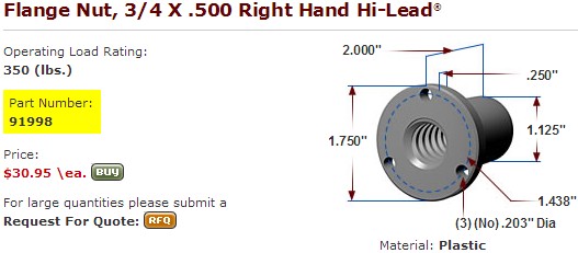
The plastic flange nuts for the Dia .750 lead screw cost $30.95 each.
[www.roton.com]
Roton Dia 0.75” x 0.50” lead:
Pitch (multi start thread) = 0.50”.
Thread starts =4.
Lead of a multi start thread = No of thread starts x pitch
Lead = 2.00”.
Lead angle = arctan(lead / pi x dia of helix):
Lead angle @ pitch dia = arctan(2.00” / 3.1415 x 0.665”): = 43.75 degrees.
Acme-threaded power screw, pg7:
Tr = (((F/cos a) x dm) / 2) x ( (l + pi x u x dm x sec a) / (pi x dm – u x l x sec a) ):
Variables:
F = 5 lbs
a = 43.75 deg
dm = 0.665”
l = 2.00”
u = 0.20
Tr = (((5 lbs/cos 43.75 deg) x 0.665 ”) / 2) x ( (2.00” + 3.1415 x 0.20 x 0.665 ” x sec 43.75 deg) / (3.1415 x 0.665 ” – 0.20 x 2.00” x sec 43.75 deg) ):
Tr = 2.30 x ( 2.58 / (2.09 – .5537) )
Tr = 2.30 x ( 2.58 / 1.5354 )
Tr = 2.30 x 1.68
Tr = 3.86 lb-in
The motors with drivers that you have chosen sound good. I'm looking forward to purchasing them.
I didn't realize that the firmware would need some tweaking, sounds like a non issue.
Does the half current back off mode imply that holding torque is turned off? If I use the Dia 1.00” x 1 lead screw,
will I run the risk of the arms falling down?
Your motor will have to spin faster, but you will be able to lift ~3X more weight by halving the pitch over a Dia 1.00” x 1.00" lead screw.
The steppers with the Dia .75” lead screw system can handle ~21 lbs, or more.
You are giving up the ability to manually set the stops, which is a non issue.
Note: The coefficient of friction that I used (0.08) was for hardened steel or bronze.
If you are using a plastic nut the starting friction will be greater (0.20).
I hadn't considered purchasing the nuts, as they are so expensive for the Dia 1.00”.
Now I'm wondering what the backlash will be like for the Dia .75” lead screw flanged plastic nut?
It would eliminate a lot of work making my own nut.
Coefficient of friction of Polyethylene on steel is 0.20 (dry and clean).
[en.wikipedia.org]
[en.wikipedia.org]
The plastic flange nuts for the Dia .750 lead screw cost $30.95 each.
[www.roton.com]
Roton Dia 0.75” x 0.50” lead:
Pitch (multi start thread) = 0.50”.
Thread starts =4.
Lead of a multi start thread = No of thread starts x pitch
Lead = 2.00”.
Lead angle = arctan(lead / pi x dia of helix):
Lead angle @ pitch dia = arctan(2.00” / 3.1415 x 0.665”): = 43.75 degrees.
Acme-threaded power screw, pg7:
Tr = (((F/cos a) x dm) / 2) x ( (l + pi x u x dm x sec a) / (pi x dm – u x l x sec a) ):
Variables:
F = 5 lbs
a = 43.75 deg
dm = 0.665”
l = 2.00”
u = 0.20
Tr = (((5 lbs/cos 43.75 deg) x 0.665 ”) / 2) x ( (2.00” + 3.1415 x 0.20 x 0.665 ” x sec 43.75 deg) / (3.1415 x 0.665 ” – 0.20 x 2.00” x sec 43.75 deg) ):
Tr = 2.30 x ( 2.58 / (2.09 – .5537) )
Tr = 2.30 x ( 2.58 / 1.5354 )
Tr = 2.30 x 1.68
Tr = 3.86 lb-in
The motors with drivers that you have chosen sound good. I'm looking forward to purchasing them.
I didn't realize that the firmware would need some tweaking, sounds like a non issue.
Does the half current back off mode imply that holding torque is turned off? If I use the Dia 1.00” x 1 lead screw,
will I run the risk of the arms falling down?
|
Re: LISA Simpson December 17, 2013 03:32PM |
Registered: 10 years ago Posts: 26 |
I have a PCB/ribbon cable adapter for the driver socket on a RAMPs board to the PMinMO open source standard for stepper motor drivers which works with the Linistepper, THB6064 and other drivers. I'm happy to share a few of them with anyone who is building an oversized LISA Simpson assuming you will post your results.
[www.linistepper.com] Open source stepper motor drivers.
[www.linistepper.com] Open source stepper motor drivers.
|
Re: LISA Simpson December 17, 2013 08:41PM |
Registered: 10 years ago Posts: 1,433 |
Looks like your little board and the one I just laid out are heading in slightly different directions. I'm mounting a set of transistors (FNJ3305's) and current limiting resistors on the Poulu header. The 4 wire cable to the opto isolators will connect through the connector that normally goes to the motor. If I need to pulse stretch the step pulse I'll put something on the header. The stepper (hopefully) will get up to the 600 to 1200 rpm range. With a 200 step motor that puts the drive into the 500 to 1000 Hz range. With 16 micro steps it will be into the 30 to 60 K steps / second range.
I'm probably not going to build anything until I get to poke a bit at the motors and controllers. They come with a break out board for a PC. That should let me test them without a lot of nutty work.
--------------
Sitting at 1/2 current, your stepper will have 1/2 torque (roughly). If that will not hold up a static load, the stepper has no chance at all with a dynamic load. It will not be able to accelerate it without some "spare" torque.
-------------
I did look into the lower power controllers for running an extruder. They are pretty cheap at eBay prices. Roughly $15 to $20 will get one delivered to your front door. If I'm going to have a Ramps anyway, there's not a lot of reason to go with one. If I do a full up Ramps replacement it would be the way I would go. Get all the motor drivers and all the high power off of the (much simpler) board.
Edited 1 time(s). Last edit at 12/17/2013 08:43PM by uncle_bob.
|
Re: LISA Simpson December 17, 2013 09:12PM |
Registered: 10 years ago Posts: 1,381 |
@uncle_bob
I plan to purchase the same steppers, and drivers that you are/have, I hope to mirror your electronics.
I've done breadboard work, soldering, played around with TI 555 timer, LED's, simple things, but nothing like this.
Can you provide instructions for the noob?
Can I do CAD work for you in exchange?
Tks.
|
Re: LISA Simpson December 18, 2013 07:44AM |
Registered: 10 years ago Posts: 1,433 |
As I mentioned in the post where I bought the motors - they do have some risk associated with them. Hold off on a buy until I at least touch them. I've still got some research to do on them.
The plug in boards should be trivial to build. Three TO-92 transistor packages, three 1/8W leaded resistors, two strips of 0.1" connectors (normal Arduino header parts). No surface mount no silly stuff. I'll post all the details (open source) once I suspect they actually work. All the electronics are stock items at Mouser. The shipping will cost you more than the parts for the 3 you would need plus a full set of spares....
The plug in boards should be trivial to build. Three TO-92 transistor packages, three 1/8W leaded resistors, two strips of 0.1" connectors (normal Arduino header parts). No surface mount no silly stuff. I'll post all the details (open source) once I suspect they actually work. All the electronics are stock items at Mouser. The shipping will cost you more than the parts for the 3 you would need plus a full set of spares....
|
Re: LISA Simpson December 18, 2013 10:43AM |
Registered: 10 years ago Posts: 1,381 |
@uncle_bob
Tks!
Anti Backlash Flange Nut:
I'm thinking of ways to incorporate an anti backlash feature onto the Dia 3/4" x .50" lead screw flange nut.
It might be possible to to thread the end of the flange nut with a NPT 3/4" die,
which would then allow you to screw on a bushing to compress the thread to take up the backlash.
Method:
Grind a lead in angle on to the Dia. 1.125" end so a 3/4" NPT die can fit over it.
Cut threads into the O.D. of the flange nut.
Cut 1 narrow slot down the center of the flange nut.
Remove all internal burrs. Thermal deburring might work, but I don't know what plastic it's made of.
Screw on a metal or plastic NPT bushing, coupler, reducer, etc., to compress the flange nut.
Done!
Edited 2 time(s). Last edit at 12/18/2013 10:45AM by A2.
Tks!

Anti Backlash Flange Nut:
I'm thinking of ways to incorporate an anti backlash feature onto the Dia 3/4" x .50" lead screw flange nut.
It might be possible to to thread the end of the flange nut with a NPT 3/4" die,
which would then allow you to screw on a bushing to compress the thread to take up the backlash.
Method:
Grind a lead in angle on to the Dia. 1.125" end so a 3/4" NPT die can fit over it.
Cut threads into the O.D. of the flange nut.
Cut 1 narrow slot down the center of the flange nut.
Remove all internal burrs. Thermal deburring might work, but I don't know what plastic it's made of.
Screw on a metal or plastic NPT bushing, coupler, reducer, etc., to compress the flange nut.
Done!
Edited 2 time(s). Last edit at 12/18/2013 10:45AM by A2.
|
Re: LISA Simpson December 18, 2013 01:05PM |
Registered: 10 years ago Posts: 1,433 |
I'm wondering if there is an even simpler (but more expensive) way to take care of the backlash (if it's even an issue). This monster may be heavy enough that it really does not have much backlash.:
Buy two of the nuts and mount them flange to flange. Put some springs in the middle of the resulting "sandwich" and you have a pretty tight nut. If nothing else, it would double the length of the nut on the shaft and reduce the tendency of the assembly to tip back and forth.
I’ll try the printed shoulder approach from the original first and see how things work out. Since it’s a printed part it’s essentially free. (Real good reason to get a kit printer going first …).
One concern I have about going to crazy with the anti-backlash stuff is that everything probably will wear faster.
--------------------------------------------------------------------
I pinged Wantai about the max speed of the stepper controller. The person on the quick answer line didn’t know the answer. Since it was the middle of the night over there I was impressed there was a real person on the other end. Hopefully I will get an email with more data in the next day or so. The quick answer was that they probably would be good to > 600 rpm. That’s fast enough for me to print at a reasonable speed with a 0.5” thread. Hopefully the real answer will confirm at least that speed with some level of micro stepping.
--------------------------------------------------------------------
There is another side to this. After digging into the stepper code in Marlin, it will only step just so fast. It may not be happy at all (it looks like it throws an error message ...) at the kind of speeds and steps I'd love to be able to run. The ARM based solution may come into play sooner than I'd thought. I'm pretty sure it will be needed for the "ultimate" >500K steps/second solution. The Mega isn't all that fast... Of course the controller is only a 200KHz PWM so it's unlikely to be happy at that rate either. So much for 128 microsteps ....
|
Re: LISA Simpson December 18, 2013 01:12PM |
Registered: 11 years ago Posts: 979 |
@uncle_bob: Backlash wasn't a problem for me. I think we should be in the mode of not fixing it until we see artifacts from it. The two nut idea will work but you have to be careful where the springs are. One nut needs to float with a spring contact that pulls away any play.
FWIW, I design for 600RPM as my max working speed. Many stepper charts that I have found show this to be the point where you drop to about 1/2 torque.
Edited 1 time(s). Last edit at 12/18/2013 01:45PM by nicholas.seward.
FWIW, I design for 600RPM as my max working speed. Many stepper charts that I have found show this to be the point where you drop to about 1/2 torque.
Edited 1 time(s). Last edit at 12/18/2013 01:45PM by nicholas.seward.
|
Re: LISA Simpson December 18, 2013 04:42PM |
Registered: 10 years ago Posts: 1,433 |
I don't really expect to run this beast at 2400 RPM. I believe that 100mm/sec is about as fast as you can reasonably print plastic. Yes, that's open to nearly infinite debate, and yes I have run a lot faster than that on occasion.
If the machine gets into the 60 to 100 mm/sec range, fine by me. At least by my current calc’s each screw would hit 130 mm/sec at 10.23 revs/second. That’s also the point where the motors go from needing a 36V supply to needing a 48V supply with 3A of drive (they are rated for 4.2A). 90 mm / sec gives me 7 revs / second and I can hit 4.2A out of a 36V supply.
Yes, I'm mixing hot end speed with the speed of the nuts on the screws. That's not something that maps 1:1. I'm sure one screw goes a bit crazy as you bring the effector close to it. About all I can really say without some more math is that it's in the right ball park. That's good enough to continue with the design.
|
Re: LISA Simpson December 19, 2013 11:25AM |
Registered: 12 years ago Posts: 85 |
|
Re: LISA Simpson December 19, 2013 11:44AM |
Registered: 11 years ago Posts: 979 |
|
Re: LISA Simpson December 19, 2013 12:04PM |
Registered: 10 years ago Posts: 1,433 |
I certainly plan on having a 0.6 mm nozzle handy. I'm not quite sure how well it will feed off of 1.75 mm filament.
---------------------
Did some indirect digging on Marlin and the Wantai stepper drivers. It appears that the current version of Marlin puts out 3 us step pulses. The controller should be happy with 1.5 us, so there's some margin. The controller wants the direction or enable to be changed 5 us ahead of a step command. From looking at the code, I doubt that will be a problem. It's a single added line of code if it is. If we enable end stops, that adds more delay on direction changes, we are certainly safe then. The max step rate is 80KHz in this version. It's not clear if it can get there and still do anything else (like accept new comands ...).
That's all for the main body of code. I would not recomend playing with the "babystepping" option unless it gets checked out a bit more than I had time for.
Edited 1 time(s). Last edit at 12/19/2013 12:06PM by uncle_bob.
|
Re: LISA Simpson December 19, 2013 12:29PM |
Registered: 10 years ago Posts: 1,381 |
@jason.fisher
I'm going to try to use oval welding rod, it's really cheap, $7.03/lbs bulk!
5/32" (3.97 mm)
3/16" (4.76 mm)
Extruder Drive Design Ideas for Inexpensive Oval Welding Rod
[forums.reprap.org]
Custom extruder for the oval welding rod:
Improved 3D printer extruder allows more plastic options
[www.kickstarter.com]
Edited 1 time(s). Last edit at 12/19/2013 12:30PM by A2.
I'm going to try to use oval welding rod, it's really cheap, $7.03/lbs bulk!
5/32" (3.97 mm)
3/16" (4.76 mm)

Extruder Drive Design Ideas for Inexpensive Oval Welding Rod
[forums.reprap.org]
Custom extruder for the oval welding rod:
Improved 3D printer extruder allows more plastic options
[www.kickstarter.com]
Edited 1 time(s). Last edit at 12/19/2013 12:30PM by A2.
|
Re: LISA Simpson December 19, 2013 10:13PM |
Registered: 10 years ago Posts: 1,433 |
Based on the comments in those threads about shrink during cool down, I'm not sure I would want to try all of that on a large format machine that does not have a full heated enclosure and a big heated bed. I have no problem with eventually having a heated bed. I'd like to avoid it right up front.
|
Re: LISA Simpson December 21, 2013 11:09AM |
Registered: 10 years ago Posts: 1,381 |
Quote
uncle_bob
Based on the comments in those threads about shrink during cool down,
I'm not sure I would want to try all of that on a large format machine that does not have a full heated enclosure and a big heated bed.
I have no problem with eventually having a heated bed. I'd like to avoid it right up front.
The shrink rate of PP, and HDPE is among the worst.
I plan to have a heated bed and enclosure.
Big parts warrant it.
I'm considering a cool down program to deal with the massive shrink rate.
My enclosure will look some thing like this:

[www.wasproject.it]
Edited 1 time(s). Last edit at 12/21/2013 11:10AM by A2.
|
Re: LISA Simpson December 21, 2013 11:37AM |
Registered: 10 years ago Posts: 1,433 |
I don't know enough about those plastics to know how hot you will need to run your enclosure to control shrink. I also don't know enough about them to know if there is a temperature where shrink is a lesser issue and you still can control the print (ooze and sag issues). My *guess* is that you will have to run it fairly hot (50 to 80C).
What I do know is that if it's hot enough, you will have problems with your electronics. None of this stuff is rated past about 50C. Inevitably that's in fast moving air or it's case temperature(!!!). If you will have the motors inside the enclosure, you will need to derate them. Their insulation is good to 130C. The current rating is based on an 80C internal rise relative to 50C outside. I believe that's one of the "forced air at 599 mph" ratings. You normally run the motors at half current to keep the case at a reasonable temperature. If you want to be able to get to 90 or so outside, you would need to cut the current in half again. Your 400 oz-in motors went to 200 oz-in and now to 100 oz-in. The power supply and drivers will need to be outside the enclosure as will the Mega / Ramps combo. I *could* design stuff that would run in that environment, you very much would not want to see what it costs done with all high temp parts in small volume.
Possibly easier alternative:
Just heat the printing area. Use some sort of foam / plywood clip on doors. It's less volume to heat, and a lot easier to build. If you have a few fans, gradients should not be to bad.


Sorry, only registered users may post in this forum.