LISA Simpson
Posted by nicholas.seward
|
Re: LISA Simpson December 08, 2013 04:55AM |
Registered: 10 years ago Posts: 1,381 |
@nicholas.seward
Renders look great!
Build area:
For a given arm length, they can only reach so far.
How are you able to increase the lower platen build size without increasing the arm length?
Are you limited by the supply of basalt platens that you have on hand?
If that's the case, can you tell us what the maximum bolt hole diameter that we can use?
I read in these forums that people who like to make vases prefer a taller build envelope,
and people who build mechanical things prefer a larger X,Y build area.
Given a choice, I would prefer to have a larger X,Y base over a taller Z axis.
Enclosure:
The two slots in the top platen work against the function of an incubated enclosure.
Were the slots for another purpose, before deciding to add the side panels?
Adding foam weather stripping would aid in sealing up the perimeter of the side panels.
7/16" lead screw:
I imagine that the 7/16" lead screw will require a larger bearing, and will cost more,
but that is not a deal breaker for me.
Have you a bearing in mind?
|
Re: LISA Simpson December 08, 2013 05:13AM |
Registered: 10 years ago Posts: 979 |
@A2: The relationship between the screw spacing, arm length, hub offset, and shoulder offset is complex. If you want to increase the xy then you will probably increase each of these a little.
The holes on the top are a hand hold. You can easily put a book on top of them if you want a heated chamber. (I print in PLA only so this is not something I choose to focus on. I am sure people will come up with all sorts of solutions.)
The bearings will be 1607s. They are about $10 more for what I need.
|
Re: LISA Simpson December 08, 2013 08:18AM |
Registered: 10 years ago Posts: 979 |
[github.com]
Files are posted. I changed everything over to the 7/16" screw. I haven't tested this screw so beware. I have it ordered and we will know soon.
I am working on the BOM. It should be posted soon.
Inventor Viewer will let you open my source files and take measurements and see how everything goes together.
I would encourage any builders to post here so this thread doesn't get too crazy.
Edited 1 time(s). Last edit at 12/08/2013 08:27AM by nicholas.seward.
|
Re: LISA Simpson December 08, 2013 09:00AM |
Registered: 11 years ago Posts: 37 |
|
Re: LISA Simpson December 08, 2013 09:06AM |
Registered: 10 years ago Posts: 979 |
@jon_bondy: I considered home on the center crosshairs. The problem is that this would be a pain manually. (You have to pay attention.) Homing at the top is easy manually and electronically.
I was also dubious. However, the repeatablility is amazing. It always freaks me out as the effector plunges at 200mm/s and stops at (0,0,5).
I was also dubious. However, the repeatablility is amazing. It always freaks me out as the effector plunges at 200mm/s and stops at (0,0,5).
|
Re: LISA Simpson December 08, 2013 09:20AM |
Registered: 11 years ago Posts: 37 |
|
Re: LISA Simpson December 08, 2013 09:34AM |
Registered: 10 years ago Posts: 979 |
@jon_bondy:
[github.com]
At the bottom right of this link is a download all button. It is 100MB. Sorry about that. I will see if there is a way to download a particular folder.
[github.com]
At the bottom right of this link is a download all button. It is 100MB. Sorry about that. I will see if there is a way to download a particular folder.
|
Re: LISA Simpson December 08, 2013 09:38AM |
Registered: 11 years ago Posts: 37 |
|
Re: LISA Simpson December 08, 2013 11:09AM |
Registered: 11 years ago Posts: 1,049 |

|
Re: LISA Simpson December 08, 2013 06:22PM |
Registered: 10 years ago Posts: 47 |
Nicholas,
that's great timing. This morning I was just about to start printing all of the pieces for the 3/8 screw . Okay, I'm on board for the 7/16 screw, and another reason to switch is the 3/8 screws that we bought were steel and in my climate here in Florida there's already surface rust so I think I'll go for 7/16 stainless screw this time. It is a lot of money but I think in the long run it'll be worth the maintenance-free aspect of stainless.
Monday I will check to see how much the tap is for the 7/16 screw, I think it'll probably pay even if only a few of us are interested in this build.
And thanks for all of the files even though Inventor doesn't like to play nice with Solid works.
|
Re: LISA Simpson December 08, 2013 06:24PM |
Registered: 10 years ago Posts: 979 |
|
Re: LISA Simpson December 08, 2013 07:57PM |
Registered: 10 years ago Posts: 1,433 |
|
Re: LISA Simpson December 08, 2013 08:06PM |
Registered: 10 years ago Posts: 47 |
|
Re: LISA Simpson December 08, 2013 10:56PM |
Registered: 10 years ago Posts: 1,381 |

This is an interesting anti-backlash design from Roton.
The spring is automatically taking up the backlash.
This design looks like it would be suited for rough 3d printed threads.
[www.roton.com]
Edited 1 time(s). Last edit at 12/08/2013 10:56PM by A2.
|
Re: LISA Simpson December 08, 2013 11:04PM |
Registered: 10 years ago Posts: 979 |
@A2: Those would work with the sleeve. I didn't initially use them because of the cost and they don't stand up to as much torque. I might try printing some nuts to see how good I can make them. Two loose nuts with a spring between them would work. However, I would have to source the spring and really tweak the nut prints. I figured the $60 for the ROTON nuts was worth all the time I would put into that.
|
Re: LISA Simpson December 09, 2013 01:04PM |
Registered: 10 years ago Posts: 1,433 |
I may well be confused, it's happened before .....
1) The precision of the printer is directly related to the hole locations in the plywood plates.
2) My tired old hands and an electric drill likely aren't the best way to locate them
3) I don't seem to have a mill that will handle 1/2 meter square objects (I believe the bases are 500mm on a side triangles)
4) Laser cutting of plywood at 1/2" does not seem to work very well.
5) Building a large CNC router from scratch sounds like fun, but it's not on my Christmas list
What's the best approach for coming up with some plywood parts?
(like I said, I may be missing something really obvious ...)
|
Re: LISA Simpson December 09, 2013 01:50PM |
Registered: 10 years ago Posts: 979 |
@uncle_bob:
1) A compass, a drill press, and some TLC will outperform most mills. My LISA was built with a hobby mill with .5mm backlash. I am sure you can do better than that.
4) You can laminate several layers of 5mm or 6mm. This will allow you to do faux counter sinking.
5) If I was you I would get a drill press and do this by hand.
Not that you shouldn't try to make it perfect but bed leveling and calibration can take up some of the slack.
If you want to laser cut them let me know and I will make the files.
|
Re: LISA Simpson December 09, 2013 02:27PM |
Registered: 10 years ago Posts: 1,381 |
|
Re: LISA Simpson December 09, 2013 02:38PM |
Registered: 10 years ago Posts: 979 |
@A2: This is the plate that has the basalt bed on top. The holes are 300mm from each other. The basalt mounting holes are 250mm from each other.
You can increase the spacing and lengthen the arms if you want a wider build area. You can also do the reverse if you want a narrower build area. Simple rule of thumb is 2/3*(screw spacing)=arm length.
You can increase the spacing and lengthen the arms if you want a wider build area. You can also do the reverse if you want a narrower build area. Simple rule of thumb is 2/3*(screw spacing)=arm length.
|
Re: LISA Simpson December 09, 2013 06:11PM |
Registered: 10 years ago Posts: 1,381 |


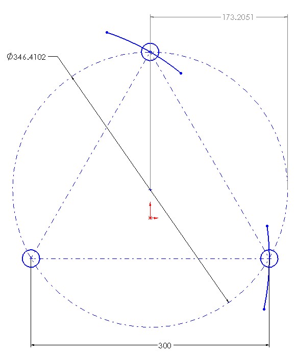
This layout is better, as you you can locate two holes with the same reference.
It's also much easier to discern where the two lines intersect.
How to locate the holes for the bearings in the upper and lower platens.
You can save some time by clamping the upper and lower platens together, and drill all the holes in one go.
Close enough method:
1. Make sure you have accurately set your lengths.
2. Draw a circle with a radius of 173.2.
3. Choose a starting point on the circle for the first hole location.
4. Draw an arc with a radius of 300 mm, where the arc crosses the Dia 173.2 circle is the center of one of the holes for the Roton lead screw.
If you want to get precise by doing it by hand do the following.
1. Make sure you have accurately set your lengths. Use a loop (magnifying glass) to set your tools.
2. Coat the location of the holes with epoxy, mix in a black filler (ground up pencil lead will work).
3. Place a piece of saran wrap over the epoxy, and weight it down with a piece of glass.
4. After the epoxy has dried layout the holes.
5. Use an eye loop and by hand and with an awl press into the cross hairs.
6. Review your work, if it does not look like it is perfectly centered with your aided eye (loop), push the center prick mark back on center.
7. Drill with a very small drill a hole into the prick mark, this will be your pilot and guide for the next drill.
8. Step drill until you reach the final hole size.
Practice first on a piece of scrap material until you are comfortable. Practice on holes separated by 5.0 inches, that way you can verify your work with calipers. Leave the drill bit in the hole and use it as a pin to measure the center to center distance.
Your millage may vary, but I think if you have never done this before that you should be able to get your holes laid out to within.005" to .015", if your layout lengths are correct.
Edited 4 time(s). Last edit at 12/09/2013 06:25PM by A2.
|
Re: LISA Simpson December 09, 2013 06:33PM |
Registered: 10 years ago Posts: 1,433 |
Thanks for the ideas. Gang drilling pilot holes in all three plates at one time seems like a do-able thing.
Sounds like it's time to dig out the big table and strap it on the drill press. Probably worth printing up some sort of hole location fixture for the motor mount holes.
Edited 1 time(s). Last edit at 12/09/2013 06:35PM by uncle_bob.
Sounds like it's time to dig out the big table and strap it on the drill press. Probably worth printing up some sort of hole location fixture for the motor mount holes.
Edited 1 time(s). Last edit at 12/09/2013 06:35PM by uncle_bob.
|
Re: LISA Simpson December 09, 2013 07:00PM |
Registered: 10 years ago Posts: 47 |
Well, I ordered the screws today 7/16 steel , after talking to Roton they informed me that stainless steel was not available. I think the solution for me is to nickel plate for protection against rust. I can do this in my shop, it's actually quite easy.
I also inquired about the tap for the 7/16 -10 and they let me know that it was proprietary shape and that they were not going to sell it to us.
@ Nicholas I'm successfully printing part out but my question is how accurate do they have to be. The overall dimensions are good but it's very difficult getting the receptacles for the bearings to even get close to the proper diameter. (Always Undersized )
|
Re: LISA Simpson December 09, 2013 07:34PM |
Registered: 10 years ago Posts: 979 |
@uncle_bob: I would advise against A2's method for locating the holes. (Sorry A2.) I would use this technique to lay out your holes. No math required and less of a chance for roundoff error to mess you up.
I actually take it a step farther. Set your compass using a ruler. You want to be close but in the end it just matters that all the holes are evenly spaces so don't stress this part too much. You can play with the screw spacing value in the software. So you set your compass. Set you compass and draw a quarter circle. Pick a point low on the quarter circle and swing an arc to intersect the arc you are on. To verify you did everything right go to that intersection and make sure you can swing an arc directly through the other two points of the triangle.
If you are going to do all three at the same time you need to make a few precautions.
*Screw them together so there is no chance of them moving relative to one another during the process.
*I like to label each of the corners A, B, and C for each of the boards. Assuming you aren't perfect this will at least ensure that you will have vertical screws.
*Drill a small guide hole. Disassemble and then drill the bearing socket followed by a screw clearance hole.
To get the hole pattern for the steppers, take a piece of paper and tape it on the back of a stepper. Do a pencil rubbing of the holes. Remove and place on the board in the correct position. Use a nail or a center punch to mark through the paper. When you drill feel free to oversize the holes. This will allow the stepper to self align before you completely tighten it.
Good luck!
@Dannydefe: Put you parts in the oven on low. Take them out every minute and tap on a hard surface. Listen for the tap to turn to a thud. At that point you can insert you bearings without cracking the plastic. Don't print the couplers yet. I am going to change them soon. Do you think I could order screws for me and have you coat them for me? That would help with the backlash and they would look awesome.
I think we can make our own tap. Heat it up with a torch. Put it on a lathe and taper it. Put it on a CNC mill and cut some grooves in it. (It sounds easy to me but I am not a metal worker.) Any one out there that is good at this sort of thing, please advise.
Also, there is some discussion going on in the ConceptFORGE forum about going metric. IGUS is the most likely candidate for being a worldwide supplier. The problem with these fast travel screws is that there is no standard. You have to get the screws and the nuts from the same place. (Don't worry about losing the imperial version. GitHub will save all that information even if I don't make a new branch or folder.
|
Re: LISA Simpson December 09, 2013 08:29PM |
Registered: 10 years ago Posts: 47 |
@ Nicholas: No problem I'll be happy to nickel plate your screws. Theoretically we could change the size of the screw by leaving them in the copper plating tank longer. Maybe I'll experimentation with the 3/8 screws I have an see the results.
I think we have quite a few options on the nuts but for now I agree with you let's use the Manufactured nuts.
I think we have quite a few options on the nuts but for now I agree with you let's use the Manufactured nuts.
|
Re: LISA Simpson December 09, 2013 08:33PM |
Registered: 10 years ago Posts: 979 |
|
Re: LISA Simpson December 09, 2013 08:43PM |
Registered: 10 years ago Posts: 47 |
|
Re: LISA Simpson December 09, 2013 08:45PM |
Registered: 10 years ago Posts: 979 |
|
Re: LISA Simpson December 09, 2013 09:46PM |
Registered: 10 years ago Posts: 1,433 |
Well with all the money I'll save drilling this in the basement, there's lots more left in the cookie jar for Torqspline.
I realize nobody has ever seen a 7/16 based version (yet) so this is a bit early in the process to be asking:
How tall could you make one of these before it's "to crazy tall" to be stable?
I'm ruling out anything over 6' simply based on not having a month or two to run prints. There's also not *that* much in the cookie jar....
If I'm doing the plywood my self, making the bottom board a bit larger would be pretty easy. I'm less concerned about "tip it over" stability than about "it was printing fine yesterday and now it's not" stability. Having the thing shake it's self to death on the first print probably also counts as "not stable".
I realize nobody has ever seen a 7/16 based version (yet) so this is a bit early in the process to be asking:
How tall could you make one of these before it's "to crazy tall" to be stable?
I'm ruling out anything over 6' simply based on not having a month or two to run prints.
There's also not *that* much in the cookie jar....If I'm doing the plywood my self, making the bottom board a bit larger would be pretty easy. I'm less concerned about "tip it over" stability than about "it was printing fine yesterday and now it's not" stability. Having the thing shake it's self to death on the first print probably also counts as "not stable".
|
Re: LISA Simpson December 09, 2013 09:55PM |
Registered: 10 years ago Posts: 17 |
|
Re: LISA Simpson December 09, 2013 11:15PM |
Registered: 10 years ago Posts: 979 |
@uncle_bob: Based on some of the equations I posted above you could make the screws about 34" long. (That would have the same max deflection as the 3/8" ones I have already tested.)
Here is an approximate rule of thumb for what I consider the edge of acceptability. I would encourage people to err on the side of caution.
L=ACCEPTABLE SCREW LENGTH
d=ROOT DIAMETER OF SCREW (The diameter of the screw if you remove the threads. For instance, the 3/8" screws I tried have a root diameter of 1/4".)
L=150*d^1.33
--OR--
d=0.023*L^0.75
*Units should be in inches for these equations.
So for the 7/16" screws with a root diameter of .327" you will end of with a max safe length of about 34". If you bump up to the 3/4" screw then you can use 5' screws. If you bump up to a 1" screw you can make it 8.5' tall. (For fun I priced this last one. It comes to less than $2500 for the whole printer. For 5 times the cost you can make a printer that has 75 times the volume.)
Edited 1 time(s). Last edit at 12/09/2013 11:16PM by nicholas.seward.
Here is an approximate rule of thumb for what I consider the edge of acceptability. I would encourage people to err on the side of caution.
L=ACCEPTABLE SCREW LENGTH
d=ROOT DIAMETER OF SCREW (The diameter of the screw if you remove the threads. For instance, the 3/8" screws I tried have a root diameter of 1/4".)
L=150*d^1.33
--OR--
d=0.023*L^0.75
*Units should be in inches for these equations.

So for the 7/16" screws with a root diameter of .327" you will end of with a max safe length of about 34". If you bump up to the 3/4" screw then you can use 5' screws. If you bump up to a 1" screw you can make it 8.5' tall. (For fun I priced this last one. It comes to less than $2500 for the whole printer. For 5 times the cost you can make a printer that has 75 times the volume.)
Edited 1 time(s). Last edit at 12/09/2013 11:16PM by nicholas.seward.


Sorry, only registered users may post in this forum.