Worm Drive Grounded Delta Printer
Posted by Solidus Labs
|
Worm Drive Grounded Delta Printer November 13, 2013 10:32AM |
Registered: 10 years ago Posts: 56 |
Hi everyone. I am starting a new thread for worm driven grounded delta printers. We are branching from the main grounded delta printer thread into this new topic. [forums.reprap.org]
Last questions from the old thread:
4. Yup it’s a variable, the arms can be any lengths you choose equal length or not. Yes, in my design the arm is shorter than the forearm.
8. Axial play on stepper motors is awful, probably around 5mm. I was hoping the spring load on the motor would be enough to compensate for the axial play but it was not strong enough.
Here is my solution:
I need a mounting bracket for the stepper motors so I integrated a 608 bearing into the bracket. I tighten the worm flush to the bearing and Voilà.
Last questions from the old thread:
3.I have removed the axial play from the machine but some nozzle play still exists. I am considering some sort of spring tension. I would love to see that example.Quote
A2
Quote
Solidus Labs
1. It's a 90 tooth worm wheel.
2. Since the output of the code is in degrees, the steps per unit in the config are translated into steps per degrees. So 200*8*90/360= 400 steps per degree.
3. I will work on making a video; I have noticed that the rigidity changes depending on its position.
4. The l1 and l2 arm lengths are set in the config. They are handled in the formulas so it is not an issue.
5. I think this has been done, if the heat bed is a single sided pcb, you can print on the back. .60 FR4 is not the most rigid material so it does need some support.
6. I started with the marlin delta branch and replaced the delta formulas [github.com]
7. Closed loop is always nice, I personally prefer the dc servo setup but an encoder on an elbow could help the accuracy.
I hope I can get the calibration finished and start test printing by the end of this week.
@ Solidus Labs, thank you for your reply.
Comments:
2. 400 steps without using microsteps is pretty good resolution.
3. Interesting observation of the change of rigidity based on the arm location.
3.1 I'm wondering if there should be a torsional preload on the pivotal end effector, or a preload on the worm wheel?
Maybe a split worm wheel with a spring to preload both sides of the worm gear teeth?
3.2 I found an example of a polar bot that uses a spring to account for the singularity of the end effector.
I think there was a paper written up on it as well, and I'm unsure if a patent is being pursued.
I believe it was a torsion spring located between the pivotal end effector, and each of the arms.
The idea is to add a torque moment between the end effector and arm, such that it's always under load.
If you want to see the example, let me know and I'll search my notes for it.
4. Arm length: I'm hoping that the code can accommodate equal arm lengths, such that the delta bot can be scaled up and down in size.
Is the center to center distance of each of the arm pivots of equal distance, or is one arm shorter than the other?
7. If stepper motor encoders become a reality, I'm going to make an effort to incorporate it.
New questions:
8.1 How much axial end play is there on a NEMA 17 single shaft, and a dual shaft stepper motors?
It was pointed out to me that if there is axial end play in the stepper motor shaft that the end play will add to the backlash problem.
Axial end play could increase due to wear, this would create a serious problem for print accuracy.
8.2 Possible solution: With the teeth of the worm gear fully embedded into the worm wheel,
axial end play could be eliminated by pushing the stepper motor axially fully in one direction (i.e. towards the worm gear).
8.3 I'm thinking to minimize this potential problem a dual shaft stepper motor should be used, and the ability to push the motor forward axially.
I'm guessing that a single shaft stepper motor is only pocketing the stub shaft end in a bronze bushing,
while the exposed shaft is press fit into a roller bearing.
I would like to hear what others think of this potential problem.
8.4 Is axial end play at fault for the lack of rigidity of the end effector in some locations over the print bed?
9.0 Do you or any one else know where I can find a specification of NEMA 17 stepper motor shaft end play?
FYI: I don't have a motor to test.
10.0 I think it's time to start a new forum thread specifically for “Worm Drive Delta Printers”.
Would you like for me to start a new thread, I'll move my questions to the new thread.
I'm looking forward to following your development efforts, and the video, good luck with your first test print!
A2
4. Yup it’s a variable, the arms can be any lengths you choose equal length or not. Yes, in my design the arm is shorter than the forearm.
8. Axial play on stepper motors is awful, probably around 5mm. I was hoping the spring load on the motor would be enough to compensate for the axial play but it was not strong enough.
Here is my solution:

I need a mounting bracket for the stepper motors so I integrated a 608 bearing into the bracket. I tighten the worm flush to the bearing and Voilà.
|
Re: Worm Drive Grounded Delta Printer November 13, 2013 11:08AM |
Registered: 10 years ago Posts: 18 |
|
Re: Worm Drive Grounded Delta Printer November 13, 2013 12:26PM |
Registered: 10 years ago Posts: 145 |
|
Re: Worm Drive Grounded Delta Printer November 13, 2013 02:45PM |
Registered: 10 years ago Posts: 56 |
It is printed with a .29 nozzle at 100 microns layer.Quote
Guizmo
Thanks for the new thread, it is much better.
I have a question as well: How did you make the wormwheel? is it printed? To me, it looks like a disc with small identations for the worm to push. I'd like to use a similar system in some drives I'm working with.
Thanks

The firmware is a modified delta marlin firmware. I am still validating eveything so I am not ready to release my changes but soon.Quote
What firmware...
|
Re: Worm Drive Grounded Delta Printer November 13, 2013 03:56PM |
Registered: 10 years ago Posts: 145 |
|
Re: Worm Drive Grounded Delta Printer November 13, 2013 05:56PM |
Registered: 10 years ago Posts: 1,381 |


Here is the link that you requested:
Backlash prevention in parallel robots
Backlash in actuators is prevented by careful design of preloaded passive joints
in the form of preloaded flexures or hinges with torsional springs.
[www.youtube.com]
Comments/Questions:
11. I like the simplicity of the torsional springs to remove backlash.
It will take away some of the force from the stepper motors, increase the tooth loading on the worm wheel,
add a little weight, and will necessitate a redesign of the end effector.
Do you think that the torsion spring is the solution?
12. Axial shaft movement: Looking forward to seeing how your new motor bracket works out for you.
Seeing that you are using a metal worm gear, you might want to add a steel washer for the worm gear to ride against.
13. I would like to see how you constructed the end effector.
Are you using a sleeve, bushing, or bearings for alignment?
I'm unsure of how it's staying together.
I'm curious if when pushed to certain locations if the end effector design is not working as expected.
14. What is the name of the extruder that you are using,
and are there dimensions/blue prints, or links of it?
Any issues with the heat from the hot end warming up the plastic, and causing it to loose it's form?
15. What is the size of the print envelope?
Is it larger, equal, or smaller than the Simpson?
Tks!
A2
Edited 1 time(s). Last edit at 11/13/2013 05:58PM by A2.
|
Re: Worm Drive Grounded Delta Printer November 14, 2013 03:24PM |
Registered: 10 years ago Posts: 56 |
Small update:
I still have a lot of calibrating to do but I couldn’t hold out any longer.
I am officially in the "I can waste filament:" stage
I still have a lot of calibrating to do but I couldn’t hold out any longer.
I am officially in the "I can waste filament:" stage

|
Re: Worm Drive Grounded Delta Printer November 14, 2013 05:11PM |
Registered: 10 years ago Posts: 1,381 |
Yea!
It's great to see the filament feeder mounted on top of the extruder!
This gives some indication of it's abilities.
I see you have the new brackets installed!
How are they working out?
If your running low on filament:
1. Go to the hardware store and purchase some Nylon weed eater filament.
Put it into the oven at 160F for a few hours to drive out the moisture.
2. In addition, I read that florist or garden centers carry a PET filament used to tie up or support plants.
Edited 1 time(s). Last edit at 11/14/2013 05:14PM by A2.
|
Re: Worm Drive Grounded Delta Printer November 14, 2013 06:52PM |
Registered: 10 years ago Posts: 145 |
|
Re: Worm Drive Grounded Delta Printer November 14, 2013 07:30PM |
Registered: 10 years ago Posts: 1,381 |
Trimmer line, comes in various sizes, I don't know if there is a standard.
I think it's cheaper than the 3D printer filament.
I imagine that there is a lot of filler in it.
2.4 mm diameter
[www.youtube.com]
1.7 mm diameter
[www.youtube.com]
Edited 1 time(s). Last edit at 11/14/2013 10:37PM by A2.
I think it's cheaper than the 3D printer filament.
I imagine that there is a lot of filler in it.
2.4 mm diameter
[www.youtube.com]
1.7 mm diameter
[www.youtube.com]
Edited 1 time(s). Last edit at 11/14/2013 10:37PM by A2.
|
Re: Worm Drive Grounded Delta Printer November 14, 2013 10:05PM |
Registered: 10 years ago Posts: 56 |
11. It appears that there is very little or no backlash on the worm gears which i am pleased about. The play is caused by the horizontal pivots. I am thinking of using a spring between the first arm and the base to keep the play forced in one direction/Quote
A2
Comments/Questions:
11. I like the simplicity of the torsional springs to remove backlash.
It will take away some of the force from the stepper motors, increase the tooth loading on the worm wheel,
add a little weight, and will necessitate a redesign of the end effector.
Do you think that the torsion spring is the solution?
12. Axial shaft movement: Looking forward to seeing how your new motor bracket works out for you.
Seeing that you are using a metal worm gear, you might want to add a steel washer for the worm gear to ride against.
13. I would like to see how you constructed the end effector.
Are you using a sleeve, bushing, or bearings for alignment?
I'm unsure of how it's staying together.
I'm curious if when pushed to certain locations if the end effector design is not working as expected.
14. What is the name of the extruder that you are using,
and are there dimensions/blue prints, or links of it?
Any issues with the heat from the hot end warming up the plastic, and causing it to loose it's form?
15. What is the size of the print envelope?
Is it larger, equal, or smaller than the Simpson?
Tks!
A2
12. The metal worm sits and rotates against a bearing so there is no need for a washer.

13. The effector are stacked ball bearings, and the extruder is threaded to hold it together. I will take a picture the next time I take it apart.
14. It is the same extruder I created for my h-bot printer. No problems with the heat so far.
15. I think the envelope is smaller, right now i have my soft limits set to 90x90x175.
Nylon trimmer line:
I have about 10kg from an amazon sale. It works pretty well if you bake the water out and print onto a garolite XX sheet coated with wood glue.

Edited 2 time(s). Last edit at 11/14/2013 10:40PM by Solidus Labs.
|
Re: Worm Drive Grounded Delta Printer November 15, 2013 02:31AM |
Registered: 10 years ago Posts: 1,381 |
Quote
Solidus Labs
11. The play is caused by the horizontal pivots. I am thinking of using a spring between the first arm and the base to keep the play forced in one direction
11. In addition to the torsion spring:
What is the fit of the bolt to the 608 bearing like?
Is the play caused by a poor fit up between the bolt, and bearing,
or is the bearing loose in the pocket?
If the assembly is not 1:1, or a slight press fit you can do the following to tighten up the joint (tool makers trick):
Using a center punch, create dimples on the surface of the bolt in a uniform pattern.
Then using a sacrificial bearing, tap the bolt through the bearing.
Be mindful of how you are going to get the bearing off of the bolt.
You can place a large washer onto the bolt first,
and use a deep well socket to aid in removing the bearing from the bolt.
This will swage the metal down, and create a 1:1 fit to the bearing ID.
Can you envision this helping to reduce the play in the joints?
[en.wikipedia.org]
16. Stepper motor heat:
Potential problem: If the stepper motor enclosure temperature max's out to 100 C (212 F),
I think that the motor bracket will creep (warp/bend).
PLA's glass transition temperature between 60-65 °C (149 °F )
[www.reprap.org]
Creep could create a backlash problem that wouldn't be obvious right away,
especially if the bracket is made from PLA, which has a low melt temp.
Solution: add thin sheet of cork between the bracket and the stepper motor.
FYI: cork is also used as a fire break.
Cork is sold for drawer, and cabinet liners, it's sold in rolls with adhesive on one side.
17. I'm curious, how much weight would you guess that you could place on the end effector
before the worm wheel stalls or fails?
18. How long did it take you to print all the parts? Nice design by the way

19. I'm assuming you have access to a lathe to machine the worm gear.
I'm thinking of ways that some one could do this at home without a lathe or special equipment.
Possible solutions: Use a file, and a hack saw, or Dremel to remove the thread (all you need is a flat,
the whole circumference does not need to be removed), then use a hand drill, and tap for the holes.
If you carefully center punch then step drill you might get a reasonably accurate hole down the center of the worm gear.
If you spin the worm gear in a drill you might locate the center by filing a very shallow cone onto the end.
The point of the cone would be your center.
A2
Edited 3 time(s). Last edit at 11/15/2013 11:15AM by A2.
|
Re: Worm Drive Grounded Delta Printer November 15, 2013 09:51AM |
Registered: 10 years ago Posts: 145 |
|
Re: Worm Drive Grounded Delta Printer November 15, 2013 11:03AM |
Registered: 10 years ago Posts: 1,381 |
@ Guizmo
You are correct in pointing out the inconsistency of the terms used to describe the components that make up a WORM DRIVE.
The terms that we should be using are WORM and WORM WHEEL.
The assembly is called WORM DRIVE.
The screw looking part is called the WORM.
The gear looking part is called the WORM WHEEL.
List of gear nomenclature
[en.wikipedia.org]
Worm drive:
A worm drive is a gear arrangement in which a worm (which is a gear in the form of a screw) meshes with a worm gear
(which is similar in appearance to a spur gear, and is also called a worm wheel).
The terminology [Worm drive] is often confused by imprecise use of the term worm gear to refer to the worm, the worm gear,
or the worm drive as a unit.
[en.wikipedia.org]
I'm assuming that the thread form is an ACME, Solidus Labs will have to verify.
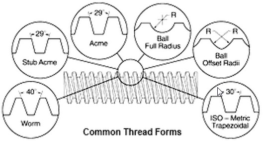
1. Thread Form
There are many different thread forms in use today.
The forms most widely used for power transmission screw threads are illustrated in Figure 43.
An optical comparator is the easiest method of determining thread form.
Profile gages, if available, and visual methods can also be used.
Great care must be taken as many forms are almost identical.
The Acme form (29 degree included angle) is only 1 degree different from the ISO Metric Trapezoidal form (30 degree included angle).
Many thread forms such as Unified, Metric ISO and Acme are subject to published standards while others,
including Ballscrew and Worm threads, are not defined in detail by any standards organizations.
[www.roton.com]
Edited 1 time(s). Last edit at 11/15/2013 11:04AM by A2.
You are correct in pointing out the inconsistency of the terms used to describe the components that make up a WORM DRIVE.
The terms that we should be using are WORM and WORM WHEEL.
The assembly is called WORM DRIVE.
The screw looking part is called the WORM.
The gear looking part is called the WORM WHEEL.
List of gear nomenclature
[en.wikipedia.org]
Worm drive:
A worm drive is a gear arrangement in which a worm (which is a gear in the form of a screw) meshes with a worm gear
(which is similar in appearance to a spur gear, and is also called a worm wheel).
The terminology [Worm drive] is often confused by imprecise use of the term worm gear to refer to the worm, the worm gear,
or the worm drive as a unit.
[en.wikipedia.org]
[forums.reprap.org]Quote
Solidus Labs
The worm wheel is 3d printer but the worm is just 1/2-10 lead screw. I usually get stock at about 10-20$ per meter.
I'm assuming that the thread form is an ACME, Solidus Labs will have to verify.
1. Thread Form
There are many different thread forms in use today.
The forms most widely used for power transmission screw threads are illustrated in Figure 43.
An optical comparator is the easiest method of determining thread form.
Profile gages, if available, and visual methods can also be used.
Great care must be taken as many forms are almost identical.
The Acme form (29 degree included angle) is only 1 degree different from the ISO Metric Trapezoidal form (30 degree included angle).
Many thread forms such as Unified, Metric ISO and Acme are subject to published standards while others,
including Ballscrew and Worm threads, are not defined in detail by any standards organizations.
[www.roton.com]

Edited 1 time(s). Last edit at 11/15/2013 11:04AM by A2.
|
Re: Worm Drive Grounded Delta Printer November 18, 2013 11:33AM |
Registered: 10 years ago Posts: 56 |
13. Well it turns out that my design for the end effector isn’t quite right. The peek insert is transferring too much heat into the bearing of the effector, softening the PLA. I think I will have to reprint these parts in abs or nylon and maybe add a fan.
@ Guizmo
19. The worm is a ACME lead screw.
I have been having a terrible time calibrating the GDR.
I have two main issues:


@ Guizmo
19. The worm is a ACME lead screw.
I have been having a terrible time calibrating the GDR.
I have two main issues:
- Movement repeatability, returning to the same location after multiple movements arrives in the same x and y position but lower in z. I think this is an arm length issue.
- Moving the head across the table does not keep a constant z height. For example moving the head from x-77.94y-45 to x77.94y45 which is aligned with the x arm slowly increased in height about .5 centimeters. I am thinking about looking into the auto bed leveling algorithm.
|
Re: Worm Drive Grounded Delta Printer November 18, 2013 03:05PM |
Registered: 10 years ago Posts: 1,381 |

13.1 Hot end heat management:
Place a heat shield in the form of a large aluminum washer between the hot end and the PEEK.
This would act as a heat shield, and heat sink which should radiate some of the heat away.
I would also try to add a piece of cork between the washer and PEEK.
13.2 Hot end design modification:
You could also minimize the contact surface area of the bearings by fluting the wall,
and adding channels to route the hot air out. If you wanted to get fancy, add an air port, and pump air into the flutes (fish tank air pump).
13.3 Shielded 608-ZZ ball bearing.
You can remove the shields to allow more air to pass through.
I would also consider flushing out the lubrication, as it will only attract debris, and insulate.
20. Equal length arms:
The Z axis is Zig Zaging down, and up, while the X, & Y maintain locational accuracy.
With equal length arms, the build envelope should increase in size.
I would think that symmetry of the delta system would be preferable.
If you decide to print equal length arms I'll buy you a roll of 1.75mm natural ABS.
I'll PM you my email address, and you can provide me with a shipping address.

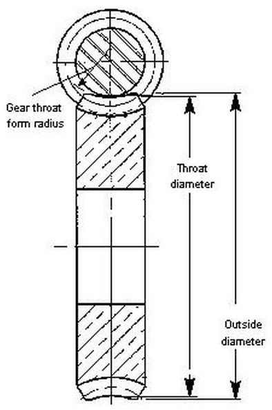
21. Worm wheel specifications:
What is the throat diameter and outside diameter of the worm wheel?
Any over riding reason that you didn't use a smaller diameter?
The larger the diameter of the worm wheel the greater the resolution.
But a lager diameter can reduce the print envelope size.
I'm trying to figure out the sweet spot, as the stepper motor 200 steps or 400 micro steps,
the length of the arm, and the worm wheel diameter effects the output precision of the arm movement.
A2
Edited 2 time(s). Last edit at 11/18/2013 06:59PM by A2.
|
Re: Worm Drive Grounded Delta Printer November 19, 2013 08:01PM |
Registered: 10 years ago Posts: 1,381 |

Maybe this will work

Process to make a round hole:
Coat a metal rod with wax (mold release).
Fill the star shaped hole with epoxy glue.
Insert the metal rod and let the epoxy cure.
Hammer out the metal rod.
Step drill to size.
lego worm gear
[www.thingiverse.com]
Edited 2 time(s). Last edit at 11/19/2013 08:07PM by A2.
|
Re: Worm Drive Grounded Delta Printer November 19, 2013 09:36PM |
Registered: 10 years ago Posts: 26 |
Quote
A2
19. I'm assuming you have access to a lathe to machine the worm gear.
I'm thinking of ways that some one could do this at home without a lathe or special equipment.
Possible solutions: Use a file, and a hack saw, or Dremel to remove the thread (all you need is a flat,
the whole circumference does not need to be removed), then use a hand drill, and tap for the holes.
If you carefully center punch then step drill you might get a reasonably accurate hole down the center of the worm gear.
If you spin the worm gear in a drill you might locate the center by filing a very shallow cone onto the end.
The point of the cone would be your center.
A2
This is also interesting to me. How about using a file / saw / Dremel to remove the threads from the entire circumference for a few mm from the end, then using a purchased shaft coupler to bridge between the motor shaft and this "turned" area. There are many pre-made couplers available. E.g.
[stores.ebay.com]
[www.linistepper.com] Open source stepper motor drivers.
|
Re: Worm Drive Grounded Delta Printer November 19, 2013 10:45PM |
Registered: 10 years ago Posts: 1,381 |
|
Re: Worm Drive Grounded Delta Printer November 20, 2013 10:50AM |
Registered: 10 years ago Posts: 56 |
@ A2
Thanks for the offer on the abs.
20. Can you explain your reason for thinking equal length arms will stop the zig zag problem? Mathematically the two arm lengths are included in the formulas as two constants L1^2+L2^2 and 2*L1*L2. Since you are solving for the vector, the arm length ratio can be any length as long as you don't violate the limits of arccosine. Changing the arm lengths to be equal might have some mathematic optimization, but I don't see how it can change the position.
21. The throat diameter is 74.3827
The reason I picked 90t worm gear is mostly arbitrarily but I wanted a gear large enough to take the strain of the arms without damaging the teeth. I don't understand you’re logic that a larger worm gear will reduce your print envelope size unless it is intruding into your printable space.
@ JamesNewton
Perhaps the simplest solution would be a printed coupler that is 1/2-10 thread on one side and 5mm on the other. Like what is used for the prusa z . [www.thingiverse.com]
Most of the load is axial so I wouldn’t expect too much flexing
|
Re: Worm Drive Grounded Delta Printer November 20, 2013 02:36PM |
Registered: 10 years ago Posts: 1,381 |
20. I don't know that different arm lengths will effect the Z axis position, I hope not.
But I wonder if the precision of the variable calculation (single, double, float), and
the ratio of the arms are not perfect maybe a small amount of "slope error" is generated in the Z axis?
Just an idea to rule out things.
21. Correct, I was thinking that a larger worm wheel will impinge on the print envelope size.
|
Re: Worm Drive Grounded Delta Printer November 20, 2013 04:10PM |
Registered: 10 years ago Posts: 26 |
Quote
A2
@ JamesNewton
It would be difficult, but not impossible to manually reduce the diameter, and maintain a concentric relationship with the the thread body.
I would question how ridged it would be under load.
Actually, it isn't all that hard if you have a hand drill, a clamp, and a good file. You just chuck the rod, then lock the drill on, and file until the thread are just gone. The point where the threads disappear into the shaft is an easy and very "automatic" stopping point. I've done that before with standard threaded rod with great success.
Quote
Solidus Labs
@ JamesNewton
Perhaps the simplest solution would be a printed coupler that is 1/2-10 thread on one side and 5mm on the other. Like what is used for the prusa z . [www.thingiverse.com]
Most of the load is axial so I wouldn’t expect too much flexing
Yes! That is a simple, effective, and very obvious solution. Thanks!
Edited 1 time(s). Last edit at 11/20/2013 04:14PM by JamesNewton.
[www.linistepper.com] Open source stepper motor drivers.
|
Re: Worm Drive Grounded Delta Printer November 23, 2013 09:15AM |
Registered: 10 years ago Posts: 1,381 |
FR4 PCB Heated Bed
Would this be cheaper than purchasing a silicone heating pad?
I imagine that you could create a layout with a ruler and marker,
then using a dremel create the heater elements.
FR4 PCB Heated Bed
[www.thingiverse.com]
[www.youtube.com]
Would this be cheaper than purchasing a silicone heating pad?
I imagine that you could create a layout with a ruler and marker,
then using a dremel create the heater elements.
FR4 PCB Heated Bed
[www.thingiverse.com]
[www.youtube.com]
|
Re: Worm Drive Grounded Delta Printer November 23, 2013 10:11AM |
Registered: 10 years ago Posts: 1,381 |
@ Solidus Labs
21. Zig Zaging Up Down:
Could the error be coming from the rotation at shoulder pivots?
Maybe there is a singularity when the arm has to rotate quickly?
I showed the math to some one, and they questioned the use of acos.
They didn't explain their reasoning.
Is there a singularity at the center of the build table?
If there is, and it requires significant force to overcome, maybe the motor is skipping a step?
I'm just throwing some ideas out there...
|
Re: Worm Drive Grounded Delta Printer November 23, 2013 11:29AM |
Registered: 10 years ago Posts: 979 |
There are no singularities in the build volume. Depending on their geometry there might be a singularity when the effector is over a shoulder bolt.
A singularity is a position where a move away from it is unpredictable. (Obviously there is more to it but that is mostly it.) Simpson/GDR have a real bad singularuty when the hub attachment point and the shoulder joints are coplanar. Any stepper rotation could result in the effector going up or down depending on gravity. Luckily the effector has to go through the build platform to get to that singularity.
This is the beauty of driving the elbow. In this case it removes singularities and allows the bot to be more compact.
|
Re: Worm Drive Grounded Delta Printer November 23, 2013 04:19PM |
Registered: 10 years ago Posts: 1,381 |
@ nicholas.seward tks for your comments.
It was explained to me that when the nozzle is centered between two arms (i.e. coplanar) there will be a singularity, is that what you mean?
I can see that being a very plausible causation of the up/dn movement.
Edited 1 time(s). Last edit at 11/23/2013 07:39PM by A2.
I think your example is based in the Z axis?Quote
nicholas.seward
Simpson/GDR have a real bad singularity when the hub attachment point and the shoulder joints are coplanar.
It was explained to me that when the nozzle is centered between two arms (i.e. coplanar) there will be a singularity, is that what you mean?
Do you mean if the motor mount brackets are loose or flexing?Quote
nicholas.seward
Any stepper rotation could result in the effector going up or down depending on gravity.
I can see that being a very plausible causation of the up/dn movement.
Edited 1 time(s). Last edit at 11/23/2013 07:39PM by A2.
|
Re: Worm Drive Grounded Delta Printer November 25, 2013 11:46AM |
Registered: 10 years ago Posts: 56 |
Quote
A2
@ Solidus Labs
21. Zig Zaging Up Down:
Could the error be coming from the rotation at shoulder pivots?
Maybe there is a singularity when the arm has to rotate quickly?
I showed the math to some one, and they questioned the use of acos.
They didn't explain their reasoning.
Is there a singularity at the center of the build table?
If there is, and it requires significant force to overcome, maybe the motor is skipping a step?
I'm just throwing some ideas out there...
21. I think the zig zagging is caused from the calibrating testing I was doing. I was lowering the number of steps per degree to prevent the print head from ramming into the print bed. Because of the geometry, very small changes in some of the lengths can impact the movement in some very unexpected ways. This is making calibrating very difficult. The play in the z axis on the print head is caused by the rotation on the shoulder pivots. The play is very bad around the edges of the print bed where the arm angle is small and the horizontal pivots are close together. I added a spring to mitigate this but I think it is making movements nonlinear.
Since the worm drive is controlling the angle of the elbow between the two arms we need to solve for that angle from a SSS triangle and that formula is
A =acos( (b^2 + c^2 - a^2)/2bc )
I have been working on implementing the 49 point auto level algorithm that is built into the firmware I am using. The g29 works but after the probing the head sky rockets up on the first move. Anyone have any ideas what causes this? I also discovered that the second effector was also melted from earlier tests
|
Re: Worm Drive Grounded Delta Printer November 25, 2013 04:17PM |
Registered: 10 years ago Posts: 1,381 |
Quote
Solidus Labs
The play in the z axis on the print head is caused by the rotation on the shoulder pivots. The play is very bad around the edges of the print bed where the arm angle is small and the horizontal pivots are close together. I added a spring to mitigate this but I think it is making movements nonlinear.
I'm unsure of your use of the word “play”, I tend to think of it as the fit up between two parts being loose.
21. Are the arms consistently rising or falling at the extremes of the print envelope?
If there is change of altitude in the Z axis at the outer perimeter of the print envelope it can be accounted for,
maybe not perfectly but to a degree that it's inconsequential to our needs.
Empirical test:
Mount a dial indicator onto the end effector.
Measure the Z axis change from the center to the outside edge of the print envelope, centered between two arms, and near the pivot.
If there is an elevation change in the Z axis it can then be accounted for with either math or by adding a cam to the pivot, i.e tilting the axis of the shoulder pivot.
Shoulder pivot cam:
By angling forward or backwards the shoulder arm pivot a cam profile is created.
Ex. if you angle the shoulder pivot towards the center of the print envelope the end effector will rise as it moves to the outer perimeter of the print envelope.
If this is a solution, you can print a bracket with the required angle.
Bed leveling sounds like a cleaver way to solve this problem.
|
Re: Worm Drive Grounded Delta Printer December 05, 2013 03:10AM |
Registered: 10 years ago Posts: 1,381 |

|
Re: Worm Drive Grounded Delta Printer December 09, 2013 10:11AM |
Registered: 10 years ago Posts: 56 |
Play as in the movement is not constrained. I can grab the print head and move it up and down about 1cm. This is caused by the horizontal pivots rotating and gets worse as the angle at the elbow gets smaller. This is probably why delta bots were built suspended above their platform.Quote
A2
I'm unsure of your use of the word “play”, I tend to think of it as the fit up between two parts being loose.
21. Are the arms consistently rising or falling at the extremes of the print envelope?
If there is change of altitude in the Z axis at the outer perimeter of the print envelope it can be accounted for,
maybe not perfectly but to a degree that it's inconsequential to our needs.
Bed leveling sounds like a cleaver way to solve this problem.
21. The arms rising at the extremes is a configuration issue, if all of the parameters are set right, the print head should move parallel to the print bed. Because of the movement in the z I am unable to properly calibrate properly.
The motor bracket is fine. It requires quite a bit of force to move the motor and the shape of the worm gear prevents the worm from moving side to side.
I am considering replacing one of the arms with a parallelogram as a means to reduce the horizontal pivot rotation.
Jon @ Solidus Labs

Sorry, only registered users may post in this forum.