New arm design for Simpson style printer.
Posted by Guizmo
|
Re: New arm design for Simpson style printer. November 07, 2013 11:07AM |
Registered: 10 years ago Posts: 145 |
I'm also having a dream.
With this design, one could potentially drive more than one machine, using only 1 controller. To do that, every one of the 3 drives would need to have enough cable outputs as machines, so the cables move in parallel. This way, a farm of 3d printers could be controlled for "high" production. Of course, all the printers making the same part in parallel. And yes, more powerful motors would be needed.
With this design, one could potentially drive more than one machine, using only 1 controller. To do that, every one of the 3 drives would need to have enough cable outputs as machines, so the cables move in parallel. This way, a farm of 3d printers could be controlled for "high" production. Of course, all the printers making the same part in parallel. And yes, more powerful motors would be needed.
|
Re: New arm design for Simpson style printer. November 07, 2013 11:59AM |
Registered: 10 years ago Posts: 20 |
So I am confused Nicholas said that the design criteria was to reduce the cost of the printer to the $200 mark if possible and to make it easier to string. A remote drive Gus though an interesting idea fails to meet that design criteria in my mind. Worm gears have notorious backlash issues and are plauged by high wear and poor transmission efficiency which will be greatly exacerbated by its composition of FDM plastic. The other thing is that adding Bowden cables though easy to tension and route adds vitamins which works against the $200 price point. Also the Bowden cables would have to be tensioned significantly to have low slip but that would add friction and reduce Simpson's ability for fast dynamic moves. I think the real beauty of Simpson's design is its speed, simplicity, and high replication potential. I encourage adaptation of the design to what you feel is the best one for you but I want to see and good robust simpson design that can go into production and make an impact in the community.
That is why I would say that a printed gears joint has all of the advantages that we are looking for in a production Simpson we just need to make sure to use the right gearbox. I feel that a properly executed cycloid gearbox is far superior to a planetary gear box in efficiency, speed, backlash, and durability.
That is why I would say that a printed gears joint has all of the advantages that we are looking for in a production Simpson we just need to make sure to use the right gearbox. I feel that a properly executed cycloid gearbox is far superior to a planetary gear box in efficiency, speed, backlash, and durability.
|
Re: New arm design for Simpson style printer. November 07, 2013 12:20PM |
Registered: 10 years ago Posts: 145 |
@Dexterm2003
Well, yeah. Those are Nicholas (and I) goals . I like them and I'm working towards them, but this is not the machine to do it. This is a design to improve the user experience. A $100 bot (actually) is nice, but the current design although good for experimentation is not so good as a comercial product yet, because is dificult to assemble. Besides that, now the main factor in price reduction is the electronics. We need $60 electronics for the $100 bot. And thinking again, why not? perhaps this design could be a $110 bot and maybe you could have a $350 "farm" of 3 bots controlled by the same electronics.
I agree with you in the goals, but disagree also on some points. Some people said Simpson design wouldn't work, just by seeing it. It works. Some say worm gears don't work weel for this, but there is another guy, Jon, using them to directly drive a Simpson arm with good results, so, I would wait to test these ideas in the real world before discarding them.
As you say, we all want to have a better printer and in fact, I'm one of the first proposer of that vitaminless Simpson and the GUS semi bearingless design is a product of those ideas. So, please don't think we are lossing focus, let's encourage more ideas. Cost is important, but hey, people pay more than $2000 for a Replicator!
Also, I'm not saying this design is final. I'm no body to say that. Please contribute with a better design to improve the weak points you found. I suggest the worm drive could be replaced by the venered fishing line and a small barrel. No backlash, cheap and not so difficult to assemble.
Edited 3 time(s). Last edit at 11/07/2013 12:48PM by Guizmo.
|
Re: New arm design for Simpson style printer. November 07, 2013 12:32PM |
Registered: 10 years ago Posts: 979 |
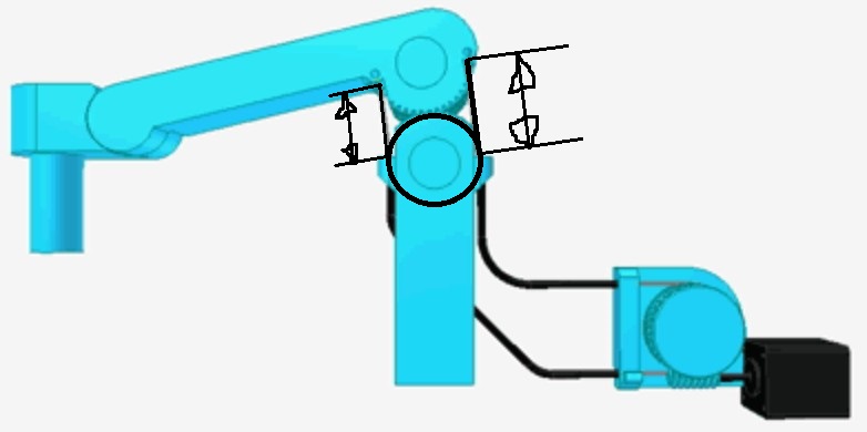
@Guizmo: I have a few concerns. The main one is the cable angling out of the arm mounts. You could have a flare on the opening but that would make the math hard. One solution would be to have a swivel mount that constrains the line of action to be where you want it. That would simplify the math.
The backlash of the worm gear doesn't concern me much. I think a worm gear is a very good choice. I would place a stiff compression springs where one of the cable sleeves terminate. That paired with the standard way one of these cables is tensioned would make for a very accurate system.
Now, there is no reason this couldn't be used in GUS's arms as is. I am sure you are aware that as you have it drawn, the proportionality has been destroyed.
All that said, I like the idea but I think we need to keep searching.
dexterm2003: We all have different goals here. I personally have conflicting goals. I want to make GUS cheaper and more robust. I am quite certain that eventually there will be a RepRap version for those that know what they are doing and a ConceptFORGE version for those that want a printer that will rarely need attention.
I am curious how you plan to incorporate a cycloidal gearbox into GUS. I can think of a few ways but they all destroy the proportionality. (That could be okay.) My initial reaction is that it won't work (of course it will work but what I mean is work and be cheap and robust) but it is one of those things that I won't fully discount until I do some testing or someone else does a little testing.
Also, I happen to think that GUS is at a local minimum in terms of cost. What I mean is that there is probably a better cheaper design out there but we will have to do more than little incremental changes to get there. I am with Guizmo that we need to focus on our goals but not get too caught up in them. Let's try things that may or may not work and see if we can slowly inch towards a better product.
|
Re: New arm design for Simpson style printer. November 07, 2013 12:44PM |
Registered: 10 years ago Posts: 145 |
@ Nicholas,
By saying "the proportionality has been destroyed" do you mean that the string length is not constant now? or are talking about the linearity between turns of the motor and final length of the arm?
Regarding the constant length of the string it is maintained constant. I analyzed many options and the gear joint is same basic design as yours. I just took off some part of the gear that wasn't been used, but the simmetry is maintained and the exiting points of the cable are exactly in the middle of the gear centers. I does have a flare as well, but your suggestion of the swivel mount is good.
|
Re: New arm design for Simpson style printer. November 07, 2013 12:53PM |
Registered: 10 years ago Posts: 979 |
@Guizmo: The cable length is constant. What I mean is that you will have to use trig unless you put this back into the GUS arm arrangement. (That is really a none issue.) The GUS arrangement is essential if you want to drive the end of the arms proportionally. That said, I was looking at an arrangement similar to yours for a gear joint SCARA. (As cool as that would be, I think I am going to keep it simple.)
|
Re: New arm design for Simpson style printer. November 07, 2013 01:03PM |
Registered: 10 years ago Posts: 145 |
Ok, I see. That was one of the first issues to be solved by this thread. I remember the "disposable knife" shape and the cams we draw. I think that issue can be solved by using a cam as well instead of a circle for the cable drum. That would be not so diffcult. I used this new orientation because it allowed me to have the mounting points of the cable accesible.
|
Re: New arm design for Simpson style printer. November 07, 2013 01:44PM |
Registered: 10 years ago Posts: 20 |

This is the idea that I had for the mockup with the cycloid drive. You are probably right about the proportionality being destroyed but it seems to me that getting the three arms to work together to maintain a fixed extruder point means that you have to do some trig anyway.
Any alternative to the PGDJ might have proportionality issues including a planetary joint. I think that it achieves several of the design goals though. Less vitamins, NO stringing issues, Little backlash, high efficiency transmission, and printable.
Remember software is cheap

|
Re: New arm design for Simpson style printer. November 07, 2013 02:07PM |
Registered: 10 years ago Posts: 979 |
@dexterm2003: The parts that I have trouble with is coming up with a design that would have no out-of-plane play in the joint. I have an idea for hourglass shaped pegs. We really need to do some testing. I assume if I make one of these joints that I will immediately have 10 ideas on how to make it even better. Also, I agree that software is cheap.
I know how these drives work but I don't think they guarantee no backlash especially with printer tolerances. Again, I would like to test it. We could probably get creative with a $0.25 spring that could produce a wear compensating/ backlash removal version.
To start the design off, I would use a 608 bearing around the eccentric input. For simplicity, we can use the cycloidal generator I posted earlier in this thread. That would mean that the pegs are the only thing that have sliding friction. Additional bearings here would be cost prohibitive. Bigger than backlash, the problem that I see is removing out of plane play in the joint. The torsional stability of an arm system is very important for Simpson or you have to go back to the double arm action.
|
Re: New arm design for Simpson style printer. November 07, 2013 03:58PM |
Registered: 10 years ago Posts: 145 |
|
Re: New arm design for Simpson style printer. November 07, 2013 05:06PM |
Registered: 10 years ago Posts: 979 |
@Guizmo: I am just referring to any wiggle or give of the joint that will lead to unwanted movement. My mental model of the joint has a little play in all 6 degrees of freedom. All my attempts to reduce the "play" end up adding to the cost. (The term Out-of-Plane is a little confusing. The plane in this context is the mathematical plane described by the movement of the arms. I know that this isn't exactly a plane but go with it. Backlash would be In-Plane but I am afraid that the two arms could be forced into a situation where they both wouldn't be on the same plane.)
For Simpson to work out we need to do two things with precision. 1) Control the elbow angle. 2) Keep all the links from the shoulder to the hub in a plane parallel with the z axis.
For Simpson to work out we need to do two things with precision. 1) Control the elbow angle. 2) Keep all the links from the shoulder to the hub in a plane parallel with the z axis.
|
Re: New arm design for Simpson style printer. November 07, 2013 05:22PM |
Registered: 10 years ago Posts: 145 |
|
Re: New arm design for Simpson style printer. November 07, 2013 06:00PM |
Registered: 10 years ago Posts: 1,381 |

@ nicholas.seward
I think Guizmo bike cables are proportional.
As one leg shortens the other leg lengthens, how is that not proportional?
@ Guizmo
There are bike cables that use solid wire, vs. braided cable.
I think a solid wire would negate any buckling that a cable my exhibit.
I think you need to add a circular wheel to the lower pivot to maintain geometric form.
As the cable is lengthened it wraps around the the circle proportionally.
Edited 1 time(s). Last edit at 11/07/2013 06:00PM by A2.
|
Re: New arm design for Simpson style printer. November 07, 2013 06:39PM |
Registered: 10 years ago Posts: 979 |
I would like to point out that if we are willing to kill the proportionality (when referring to the actuated distance vs stepper rotation) then we have a ready made solution that is pretty simple. (@A2: Guizmo's setup has the change in cable length from one side to the other be proportional. The end effector moves aren't propotional.)
This design was from my second draft of Simpson. I would change a bunch of things to bring it back up to speed but you get the idea.
Things I would fix:
1) Update the shoulders, platform, and hub to match the current GUS.
2) Make all the joint one sided instead of yoke joints. (Look at how all the arms connect for Wally and GUS. Yoke joints are better in some ways but I have found that my one sided connections are sufficient which will make assembly easier.)
3) Throw a guitar tuner on each pulley.
4) Throw on some physical end stops. (I think the weight of the steppers will hold the arms in the straight out orientation. I know a lot of people will disagree with me but trading in electrical end stops for physical ones is the way to go. This is especially true for a machine that will never get close to the physical stops in a typical print like Wally or Simpson.)
I didn't go with this design for a few reasons. The main reason was that people thought the pulleys would have too much inertia. In reality pulley inertia is very minimal but try convincing people of that. It is harder than it sounds. The other reason is the Annirak drive came along and made the math so beautiful. The final reason is that at the time my target build envelope was getting hit by the pulleys. I am not sure if this will still be an issue. The geometry of the system has evolved a little since then. I think my expanded shoulders and hub will help the pulley's clear the build envelope.
This design would be very simple and easy to maintain. Does SPUD (Simple Pulley Using Device) Simpson need to get fleshed out? (Love the acronyms. Actually, I have to name all these variants or I will get confused. I still don't have a name for the original Simpson other than saying "the original Simpson.")
|
Re: New arm design for Simpson style printer. November 07, 2013 06:51PM |
Registered: 10 years ago Posts: 145 |
Funny.
I forgot everything we had done in the last 3 months. Supposedly, in this thread I wanted to analyze and develop an arm that was equivalent to the Annirak drive but that still had enough force at the end. And so the ideas came. I believe, now that "we" (well, AFAIK only Nicholas has actually built some of the designs) have tested some ideas, we have to take the decision on simplifying the math, or simplifying the mechanics. Well, at least that is a question I ask to myself. As Nicholas said, we all have different goals.
I think I will pursue the goal of an easy to assembly machine that can still use the Annirak drive firmware, with the parallel goal of making a bearingless Simpson and lastly, migrate those joint designs to a Single arm printer.
I really want to test this RDGUS in the real world, so I will improve it. I believe it could work, and I do want to maintain it linear (distance vs motor turns) so I will do the math.
Regarding Low Vitamin Simpson I have some ideas of a bearing less joint that seem to work (I made a mockup with wood) but are more suited for a parallel type of robot. Perhaps I will begin working in a MPTIWL (more parallel than I would like) robot, cause those joints in fact behave the same as a 4 link mechanism.
LV Simpson will be the ultimate Reprap. Everyone's ideas are welcome.
PS: In fact, I'd like to propose a way to classify improvements, so every person involved can know towards which goal is directed the improvement.
For example, let's imagine I come up with a way to eliminate motors, then, that wold be classified as a "Vitamin reduction improvement"
I propose:
°Vitamin reduction (also known as Reprappiness)
°Final user experience improvement (mainly directed to reducing potential issues, although other improvements could be classified here)
°Capacity increase (speed, volume...)
°Cost reduction
°Aesthetics
°Print quality improvement
... among many others.
Do you like the idea?
Edited 3 time(s). Last edit at 11/07/2013 07:20PM by Guizmo.
|
Re: New arm design for Simpson style printer. November 07, 2013 07:18PM |
Registered: 10 years ago Posts: 145 |
@ Nicholas,
I got the name: THOR Simpson (THe ORiginal Simpson)
Regarding re-taking that design, I have to ask you a question: What would be your goal with that?
I see the potential issue of it being very slow when one arm gets close to being totally stretched (or closed), or, if you design the pulleys the other way around, the system having low resolution at 90° of the arm. (You could draw a resolution/speed map as you did with Wally, superposing the values of the 3 arms and plotting the limiting value.)
I believe linear is the way to go, but just finding a way to improve the assembly process. That could make GUS a success.
Edited 2 time(s). Last edit at 11/07/2013 07:35PM by Guizmo.
|
Re: New arm design for Simpson style printer. November 07, 2013 07:49PM |
Registered: 10 years ago Posts: 167 |
|
Re: New arm design for Simpson style printer. November 08, 2013 10:10AM |
Registered: 10 years ago Posts: 145 |
@ AbuMaia,
Which designs are you talking about? If I remember correctly, the stringing in Wally is easier to do, so probably is not an issue.
Besides that, the bowden cable arrangement is not proportional (right now), so that means different firmware.
Edited 1 time(s). Last edit at 11/08/2013 10:12AM by Guizmo.
|
THE REMOTER November 08, 2013 07:24PM |
Registered: 10 years ago Posts: 145 |
This is the remoter.
A device to remote drive a turning mechanism. It has 278° of turning capacity and a 1:1 ratio. You drive one pulley the way you prefer and the other pulley will follow. Shown in inverted motion configuration (if there is such a thing, since rotation direction is relative).
It has to be improved, according to some suggestions. Nicholas, Annirak, I know you have some ideas. Everybody else, what do you think?
It will suit perfectly to the robot arm printer I have on mind, as this will let me reduce a lot of weight. This will have its own thread. Animation pending
Edited 1 time(s). Last edit at 11/08/2013 07:34PM by Guizmo.
A device to remote drive a turning mechanism. It has 278° of turning capacity and a 1:1 ratio. You drive one pulley the way you prefer and the other pulley will follow. Shown in inverted motion configuration (if there is such a thing, since rotation direction is relative).

It has to be improved, according to some suggestions. Nicholas, Annirak, I know you have some ideas. Everybody else, what do you think?
It will suit perfectly to the robot arm printer I have on mind, as this will let me reduce a lot of weight. This will have its own thread. Animation pending
Edited 1 time(s). Last edit at 11/08/2013 07:34PM by Guizmo.
|
Re: New arm design for Simpson style printer. November 09, 2013 12:31AM |
Registered: 15 years ago Posts: 401 |
Haha, yeah, I do.
For one, you can remove a lot of force from the bearings on the drive side by making the apertures of the Bowden cables point towards each other.
I've got to say, I'm really liking the remote drive approach. I had played around with the idea of pneumatics or hydraulics, but I couldn't work out how to get the price of the actuators down low enough to be usable. Why didn't I think of Bowden!?
And there's no reason this wouldn't work with scara bots. The problems are all in the torque multiplier. I have an idea to make a zero backlash torque multiplier, but I need to put a little more work into it.
|
Re: New arm design for Simpson style printer. November 09, 2013 02:54PM |
Registered: 10 years ago Posts: 86 |
|
Re: THE REMOTER November 09, 2013 03:25PM |
Registered: 12 years ago Posts: 85 |
Very novel. Could you animate a version that has one input mechanism and two outputs? i.e for synchronizing both sides of a Prusa-style Z? You could do some pretty interesting things with multiple outputs with varying 'cam' pass-through profilers.
Quote
Guizmo
This is the remoter.
A device to remote drive a turning mechanism. It has 278° of turning capacity and a 1:1 ratio. You drive one pulley the way you prefer and the other pulley will follow. Shown in inverted motion configuration (if there is such a thing, since rotation direction is relative).
|
Re: New arm design for Simpson style printer. November 10, 2013 01:55AM |
Admin Registered: 13 years ago Posts: 730 |
Hey All, I hope this isn't too far off the present topic. It is in response to something Nicholas said the other day in this post:
So, while this doesn't address the "parts showing up at the door" aspect, it certainly may assist with the collaboration: bobc set up an example GitHub + Bountysource project for tracking and funding small open source hardware projects related to RepRap. The details of this are here: RepRap Bounties.
You guys might consider using the bounty tracker (or setting up something similar). It could help prioritize some of the action items, and reward those who develop new things and share them with the community.
Quote
nicholas.seward
I have the idealist goal that there will eventually be a place on the web where many people can collaborate on a mechanical design. After the design is "complete", anyone can order the design and all the parts will just show up at their door. Kind of like SourceForge for hardware. I think I will call it ConceptFORGE.
So, while this doesn't address the "parts showing up at the door" aspect, it certainly may assist with the collaboration: bobc set up an example GitHub + Bountysource project for tracking and funding small open source hardware projects related to RepRap. The details of this are here: RepRap Bounties.
You guys might consider using the bounty tracker (or setting up something similar). It could help prioritize some of the action items, and reward those who develop new things and share them with the community.
|
Re: New arm design for Simpson style printer. November 11, 2013 09:49AM |
Registered: 10 years ago Posts: 145 |
@ Annirak,
Thanks, great idea. I'll use it right away. I haven't considered the forces, just the functionality. That's why I like this forum, there are very experienced and smart people. For the torque multiplier, why not using, a pulley system with fishing string or even an antibacklash belt, just like "normal" reprap's?
@Magicworks,
Feel free to adapt it to any machine you want. I also see a lot of potential.
@jason.fisher
Yes, that is one capability that will open many possibilities. I'll make that animation. (EDIT: Jason, for that syncro a multiturn system is needed. This has less than a complete turn capability. Even though, I'm working on a multiturn design. I already have the design of a limited multiturn system, something around 5 turns, but a unlimited design would be great and extremely useful. Anyway, the animation is a todo)
Edited 1 time(s). Last edit at 11/11/2013 01:33PM by Guizmo.
|
Re: New arm design for Simpson style printer. November 11, 2013 12:02PM |
Registered: 10 years ago Posts: 145 |
|
Re: New arm design for Simpson style printer. November 11, 2013 07:09PM |
Registered: 10 years ago Posts: 31 |
I've redone my string analysis in GeoGebra. See the working version and run it at
[www.geogebratube.org]
It's currently set for 8mm bolts without pulleys, 50mm radius for big gear, and bolts 40mm apart.
The attached spreadsheet shows the string total length (neglecting the back side of the motor pulley or any wraps spiraling on that pulley), the string motion to get to each angle, and the reach at each angle. Then it shows the mechanical advantage versus angle. That should be constant for the proportionality to work.
If the string length is not constant, tensioning it is a problem. So the best schemes return the string to the motor side of the arm, and give both constant string length and constant mechanical advantage. But if that is too difficult, some of the odd crossings could be tolerable.
Play with angle alpha (move the slider) to see the Simpson arm bend, and see the string length vary for various winding schemes (s1, s1x, s2, s3, s4, x1, x3).
This shows that the string anchors must be on the same side as the motor in order for the string length to be constant as alpha varies.
This assumes pulleys of radius Pradius are mounted on the Simpson bolts, which are on a diameter at radius Bradius of the meshing gears (not shown) of radius Gradius. B and B' are the axes of the gears on the two arms. The effect of the meshing gears is here implicit in the reflection about the y axis.
All these dimensions can be adjusted by the corresponding slider.
The lesson I get from this study is that the string should end at the right-hand arm, because that allows both a constant string length and a constant proportionality between the string position and the Reach, or effective length of the arm.
You can see the winding scheme in detail by looking at L1s1 through L1x3 definitions and L2s1 through L2x3 below. The path appears in these definitions as a sum of the various segments and arcs that comprise it, in sequence.
You will have to zoom in to be able to read all the little arcs' labels.
L1 means Length of string 1, which connects the upper pulleys and anchor points.
L1s1 = m_3 + k_3 + m + p_1 + f_1 + u1 + f_1' +a1'
(Start at right of motor pulley, go up and kiss the lower pulley to deflect toward the upper pulley, reach the upper pulley and wrap around it about 1/4 turn, cross to left side using path u1, anchor at left along path a1'.)
L1s2 = m_3 + k_3 + m + p_1 + f_1 + u1 + f_1' + g_1' + h_1' + d1 + h_1 + b1
(Instead of ending at left, pass around the left pulley and return along path d1, then anchoring along path b1 on the right.)
L1s3 = m_3 + k_3 + m + p_1 + f_1 + u1 + f_1' + g_1' + h_1' + d1 + h_1 + k_1 + p_1 + f_1 + u1 + f_1' + a1'
(Instead of ending at the right, pass around the right pulley again and cross a second time along path u1, anchoring at left along a1'.)
L1s4 = m_3 + k_3 + m + p_1 + f_1 + u1 + f_1' + g_1' + h_1' + d1 + h_1 + k_1 + p_1 + f_1 + u1 + f_1' + g_1' + h_1' + d1 + h_1 + b1
(Instead of ending at the left, pass around the left pulley again and cross a second time along path d1, anchoring at right along b1.)
L1x1 = m_3 + k_3 + m + p_1 + f_1 + e_1 + x1 + k_4' + h_1' + b1'
(Like L1s1, except take the diagonal path x1 toward the left, anchor on the left along b1'.)
L1x3 = m_3 + k_3 + m + p_1 + f_1 + e_1 + x1 + k_4' + h_1' + g_1' + f_1' + u1 + f_1 + p_1 + k_1 + h_1 + d1 + h_1' + b1'
(Instead of ending after one crossing to left, continue back along u1 and d1, making two more crossings before ending along b1' at the left.)
(The purpose of the diagonal path is to cancel out some of the string length variation one gets with a simple single u1 path to the left, as in the L1s1 case.)
(The solution isn't ideal, however, because the mechanical advantage varies slightly as angles change.)
L2s1 = mx + h_3 + k_3 + p_2 + f_2 + u2 + f_2' + a2'
(Lower string starts at motor pulley left, diagonal up to right side of pulley c2, about 1/4 turn, cross along u2, anchor along a2'. Same path as for L1, essentially.)
L2s1x = m_3' + k_3' + p_2' + e_2 + f_2 + p_2 + k_3 + h_3 + g_3 + h_2 + d2 + h_2' + b2'
(Start at motor pulley left, straight up to left side of pulley c2, go 3/4 turn clockwise around the pulley then cross along d2 and anchor along b2'.)
(This is opposite, symmetric to, L1s1. The result is a constant string length, but the mechanical advantage varies slightly as angles change, a loss of proportionality.)
L2s2 = mx + h_3 + k_3 + p_2 + f_2 + u2 + f_2' + g_2' + h_2' + d2 + h_2 + b2
(Motor pulley left, diagonal to right side of pulley c2, counter clockwise to path u2, around pulley c2', return along d2, anchor along b2 at right.)
L2s3 = mx + h_3 + k_3 + p_2 + f_2 + u2 + f_2' + g_2' + h_2' + d2 + h_2 + g_3 + h_3 + k_3 + p_2 + f_2 + u2 + f_2' + a2'
(Motor pulley left, diagonal to right of pulley c2, counter clockwise to u2, around c2' and back along d2, around c2, to the left along u2, anchor along a2' at left.)
L2s4 = mx + h_3 + k_3 + p_2 + f_2 + u2 + f_2' + g_2' + h_2' + d2 + h_2 + g_3 + h_3 + k_3 + p_2 + f_2 + u2 + f_2' + g_2' + h_2' + d2 + h_2 + b2
(Same, but continue around c2' and return to right along d2, anchor along b2.)
L2x1 = m_3' + k_3' + p_2' + e_2 + f_2 + p_2 + k_3 + h_3 + g_3 + h_2 + k_2 + y2 + e_2' + f_2' + a2'
(Motor pulley left, straight up to left of pulley c2, 3/4 turn clockwise around c2, diagonal up to left along y2, anchor along a2'. This diagonal is symmetric opposite of L1x1 above.)
L2x3 = m_3' + k_3' + p_2' + e_2 + f_2 + p_2 + k_3 + h_3 + g_3 + h_2 + k_2 + y2 + e_2' + f_2' + g_2' + h_2' + d2 + h_2 + g_3 + h_3 + k_3 + p_2 + f_2 + u2 + f_2' + a2'
(Same, but continue around c2', return to the right alone d2, around c2 counterclockwise and return to left along u2, anchor along a2'.)
|
Re: New arm design for Simpson style printer. December 09, 2013 10:57AM |
Registered: 10 years ago Posts: 14 |
|
Re: New arm design for Simpson style printer. December 09, 2013 11:01AM |
Registered: 10 years ago Posts: 979 |
|
Re: New arm design for Simpson style printer. December 09, 2013 06:47PM |
Registered: 10 years ago Posts: 145 |

Sorry, only registered users may post in this forum.