New arm design for Simpson style printer.
Posted by Guizmo
|
Re: New arm design for Simpson style printer. October 10, 2013 04:55AM |
Registered: 10 years ago Posts: 1,381 |
No one has explained what the problem is in a manner that a student can set out and solve.
400 to 230 microns (.016” to .009”) error is not acceptable for my work.
Would a simulation like this help?
Go to the last post there is a down load video titled: Cable Roll On-Off.mp4
[forum.solidworks.com]
I still don't know what geometry is causing a nonlinearity problem.
There is not a schematic of the string routing to reference so it can be improved upon. Make a long video of how to route the string.
Nomenclature needs to be standardized, and identified on the schematic.
A2
|
Re: New arm design for Simpson style printer. October 10, 2013 07:25AM |
Registered: 11 years ago Posts: 58 |
For anyone wanting a closer look at the arms: [www.flickr.com]
This is GUS 2, so it's the original arm design with none of the improvements that Nicholas already has planned, nor anything being discussed here obviously.
This is GUS 2, so it's the original arm design with none of the improvements that Nicholas already has planned, nor anything being discussed here obviously.
|
Re: New arm design for Simpson style printer. October 10, 2013 08:50PM |
Registered: 10 years ago Posts: 31 |
A2 Wrote:
-------------------------------------------------------
> I still don't know what geometry is causing a
> nonlinearity problem.
>
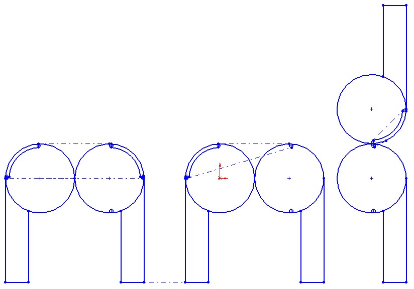
The effective line of force application needs to go through the centerlines of the bolts to get the proportionality right.
So an even number of strings, as in one loop around the slave bolts, has that property, but a single pass from one side to the other doesn't.
The angle of the strings as they pass between the arms changes with respect to the bolts (and arms). If there is a full loop, that angle change doesn't change the total string involved in the wrap around the bolt--what's lost on one side is gained on the other. Otherwise, the angle change changes the amount of string used in the arc around the bolt.
-------------------------------------------------------
> I still don't know what geometry is causing a
> nonlinearity problem.
>
The effective line of force application needs to go through the centerlines of the bolts to get the proportionality right.
So an even number of strings, as in one loop around the slave bolts, has that property, but a single pass from one side to the other doesn't.
The angle of the strings as they pass between the arms changes with respect to the bolts (and arms). If there is a full loop, that angle change doesn't change the total string involved in the wrap around the bolt--what's lost on one side is gained on the other. Otherwise, the angle change changes the amount of string used in the arc around the bolt.
|
Re: New arm design for Simpson style printer. October 10, 2013 08:55PM |
Registered: 10 years ago Posts: 979 |
|
Re: New arm design for Simpson style printer. October 11, 2013 12:27AM |
Registered: 10 years ago Posts: 1,381 |

Thank you Owen, Dave, Nicholas.
Problem:
In general you are loosing your MA as the gear drive rotates.
Idea:
Change the pulley perimeter to a cam profile, such that the MA stays consistent.
Simple sketch to stimulate ideas.
A2
Edited 1 time(s). Last edit at 10/11/2013 12:27AM by A2.
|
Re: New arm design for Simpson style printer. October 11, 2013 01:27AM |
Registered: 10 years ago Posts: 31 |
I don't see that we're losing any mechanical advantage.
When the motion at the end effector is proportional to the motion of the string (motor), that ought to mean the force ratio between motor and effector is always the same, no matter what the arm extension is.
That seems pretty ideal, to me. In fact, I think it's a wonderful feature, surprising that it's possible.
|
Re: New arm design for Simpson style printer. October 11, 2013 04:52AM |
Registered: 10 years ago Posts: 1,381 |
OK, so there are 3 solution paths available to eliminate the nonlinearity:
1. An infinity of magic loops.
2. Software, (codify the hard maths).
3. Geometric, (but no one has a clue what that might be).
No one has indicated what geometric direction we should be exploiting.
I think it's time we explore the software solution.
If the maths is brain numbing, lets break it up and work in teams and crunch it out.
What other options are there?
A2
|
Re: New arm design for Simpson style printer. October 11, 2013 09:12AM |
Registered: 10 years ago Posts: 4 |
Pardon for the uninformed interruption
I am not sure why moving back to a geard-driven system with an axis or rotation which is fixed would not be simpler;
That is, where the arms are both of the same radius and pivot on a central point.
The chord, or distance between the base and the effector then increase in a manner predictable by simple trigonometry.
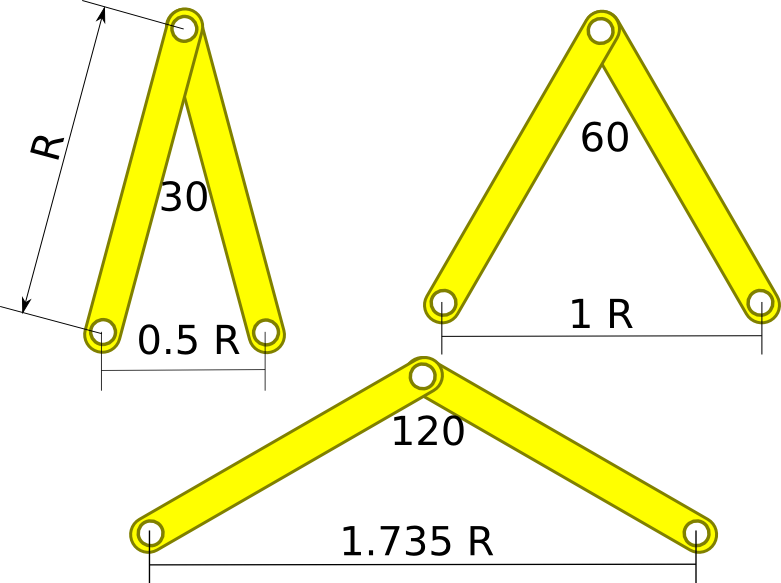
That is, for the same radii,
Chord length, a = 2R sin(1/2 * θ)
Where R = the radius or the arm and θ = the angle at the point of rotation
Thus, logically, when differentiated, the rate of change of the chord length as the angle increases, decreases as;
d/dθ = 2R cos(1/2 * θ)
And from there I can forsee two options;
1) Steps per chord mm changes in inverse proportion to 2R cos(1/2 * θ) in software
Doable in slicing post processing or in firmware - slicing probably being better given processor constraints
After all, steps are just a fraction of a radian
2) Variable mechanical ratio
Although I know you've tried this with the double laminar joint system, I wonder if non-circular gears might not be more useful? in the angle range 0 to 125 degrees, you increase in the inverse of the second equation, which doubles over that period - so you can go from 1:1 gearing up to 1:2 gearing or visa versa.
I'm wondering if this couldn't be done via gears either driven up the arm, or a planetary set at the arm axis with the stepper motor in the arm? That is, a hypocycloid gearing with a case whose ratio to the planetary gear varies with angle
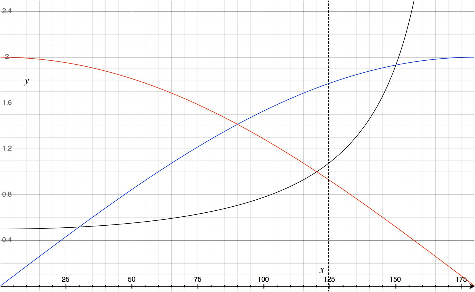
The graphs of distance (blue), rate of change with increase in angle (red) and it's inverse (black) look like this - and mean this approach would become non-trivial beyond 150 degrees (mechanically you approach infinity)
Cheers
I am not sure why moving back to a geard-driven system with an axis or rotation which is fixed would not be simpler;
That is, where the arms are both of the same radius and pivot on a central point.
The chord, or distance between the base and the effector then increase in a manner predictable by simple trigonometry.
That is, for the same radii,
Chord length, a = 2R sin(1/2 * θ)

Where R = the radius or the arm and θ = the angle at the point of rotation
Thus, logically, when differentiated, the rate of change of the chord length as the angle increases, decreases as;
d/dθ = 2R cos(1/2 * θ)
And from there I can forsee two options;
1) Steps per chord mm changes in inverse proportion to 2R cos(1/2 * θ) in software
Doable in slicing post processing or in firmware - slicing probably being better given processor constraints
After all, steps are just a fraction of a radian
2) Variable mechanical ratio
Although I know you've tried this with the double laminar joint system, I wonder if non-circular gears might not be more useful? in the angle range 0 to 125 degrees, you increase in the inverse of the second equation, which doubles over that period - so you can go from 1:1 gearing up to 1:2 gearing or visa versa.
I'm wondering if this couldn't be done via gears either driven up the arm, or a planetary set at the arm axis with the stepper motor in the arm? That is, a hypocycloid gearing with a case whose ratio to the planetary gear varies with angle
The graphs of distance (blue), rate of change with increase in angle (red) and it's inverse (black) look like this - and mean this approach would become non-trivial beyond 150 degrees (mechanically you approach infinity)

Cheers
|
Re: New arm design for Simpson style printer. October 11, 2013 11:55AM |
Registered: 15 years ago Posts: 401 |
@LShearer: That's actually, roughly, the design we started with. There are a number of optimizations that we did to get where we are now. Proportionality was a big consideration, so was zero-backlash. We managed to get rid of the belt drive by switching to the (seriously, I'm not being narcissistic; someone else named it) Annirak drive. But it had a problem with non-constant length of the drive cables, so Nick started playing with double lamina compliant joints. After I asked him for one that had a fixed drive cable length, he came up with the proportional gear-drive joint.
You can see most of the development process in this thread and in this one: [forums.reprap.org]
You can see most of the development process in this thread and in this one: [forums.reprap.org]
|
Re: New arm design for Simpson style printer. October 11, 2013 01:19PM |
Registered: 10 years ago Posts: 979 |
Quote
A2
OK, so there are 3 solution paths available to eliminate the nonlinearity:
1. An infinity of magic loops.
2. Software, (codify the hard maths).
3. Geometric, (but no one has a clue what that might be).
No one has indicated what geometric direction we should be exploiting.
I think it's time we explore the software solution.
If the maths is brain numbing, lets break it up and work in teams and crunch it out.
What other options are there?
A2
1) After about 10 loops the nonlinearity should be invisible when compared to other sources of error.
2) The math is not hard. See annirak's equations above. I haven't implemented yet because I need a few hours to make absolute certain that I make the second order adjustments in the right direction.
3) I have a few ideas but the simplest solution so far is to put the tuner and the spring on the motor arm or just adjust for it in software.
Edited 1 time(s). Last edit at 10/11/2013 01:28PM by nicholas.seward.
|
Re: New arm design for Simpson style printer. October 11, 2013 02:37PM |
Registered: 10 years ago Posts: 31 |
@LShearer
Proportional implies linear.
Driving the angle directly is simple, but the resulting arm length is not linear--there's a sin function. That's nice, but not nearly as nice as Nick's scheme.
So with the string, using proper symmetry, the length from pivot to effector is just a multiple of the string position or motor rotation.
Hard to get simpler than that.
Now, if you wish to deviate from complete symmetry for practical manufacturing reasons, some slight nonlinearity will appear, which can be compensated in software.
But if Nick is able to put the string ends both (spring and tuner peg) on the motor arm, there's no reason to have imperfect symmetry.
Personally, my worries now are more about the z axis. Seems to me z magnifies any errors in arm length, to infinity when z=0 and the pivots are level with the build platform. So the pivots need to be well below the effector ends of the arms. By how much? The length of the extruder is critical here--really the arm pivots just need to be well below where the arm effector end pivots meet the top end of the extruder.
|
Re: New arm design for Simpson style printer. October 11, 2013 08:50PM |
Registered: 10 years ago Posts: 31 |
Oh yeah...
As the build progresses, and the Z gets larger, you do still have to do the trigonometry to convert the x,y,z to the length1,length2,length3 coordinates. These lengths are diagonals, so there'll be some trig and square roots involved. So while linear (proportional) behavior is really nice, it isn't the whole solution.
As the build progresses, and the Z gets larger, you do still have to do the trigonometry to convert the x,y,z to the length1,length2,length3 coordinates. These lengths are diagonals, so there'll be some trig and square roots involved. So while linear (proportional) behavior is really nice, it isn't the whole solution.
|
Re: New arm design for Simpson style printer. October 11, 2013 09:59PM |
Registered: 10 years ago Posts: 979 |
|
Re: New arm design for Simpson style printer. October 11, 2013 10:24PM |
Registered: 10 years ago Posts: 31 |
Ahh, good point. So there's just squares and square roots.
If the end effector were really at z=0, in the plane of the arm mounting pivots, the force would be infinite when you tried to go up to z=0.00001, though, right?
So you're relying on the extruder extending below the effector ends far enough to give you some leverage. Are the arm mounting pivots level with the bed, or below it?
BTW, it looks like the last GeoGebra file I uploaded works fine as uploaded, when used via a browser, but when it is downloaded to run with the GeoGebra app it won't open without a serious error message. I'm investigating.
|
Re: New arm design for Simpson style printer. October 11, 2013 10:44PM |
Registered: 10 years ago Posts: 1,381 |

|
Re: New arm design for Simpson style printer. October 11, 2013 10:46PM |
Registered: 10 years ago Posts: 979 |

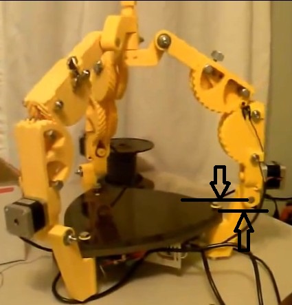
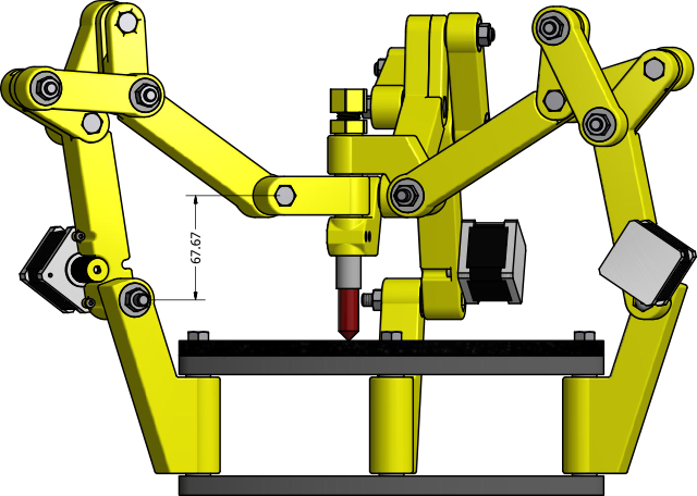
@DaveGadgeteer: Yep! Infinite force would be a bummer. There is about a 2.5" elevation between the arm ends when you are as low are you can go. I could get by with less than that. It is a balance between, [larger print volume, more force required, less speed] and [smaller print volume, less force required, more speed]. The picture shows the now abandoned xDrive but it was the most up to date model I had that I could make a quick rendering of. I am in the process of putting together the new improved GUS model. However, the geometry shown is still relevant. It doesn't matter that the arms mount above the table as long as the hub end of the arm is always elevated above the shoulder end of the arm.
Edited 2 time(s). Last edit at 10/11/2013 10:49PM by nicholas.seward.
|
Re: New arm design for Simpson style printer. October 14, 2013 04:43PM |
Registered: 10 years ago Posts: 31 |
DaveGadgeteer Wrote:
-------------------------------------------------------
> BTW, it looks like the last GeoGebra file I
> uploaded works fine as uploaded, when used via a
> browser, but when it is downloaded to run with the
> GeoGebra app it won't open without a serious error
> message. I'm investigating.
This seems to have been a problem with which version of GeoGebra you are running.
It works fine with the "beta" version that is available at the Apple App Store (which is known as 4.4 beta by experts, but is "About box" labeled 4.3.45.0 instead!
It's possible that a fresh install was also required, because to get it working I deleted my old 4.3.45 and re-downloaded and installed using the App store, and then it all worked again.
I'm experimenting with a custom tool for it that would make defining tangent segments reliable without so much hassle, but no promises yet. (Problem is the tangent lines, with roundoff errors, sometimes don't quite touch the circle as things are moved, which causes the intersection points to become undefined. The fix is to insert a hidden perpendicular from the circle center, and that intersection is robust against roundoff.)
|
Re: New arm design for Simpson style printer. October 14, 2013 07:27PM |
Registered: 10 years ago Posts: 145 |
Guys,
Talking of a bit different suff. I found this sensor, that could be used for the bed calibration. It is a distance sensor with a range of 0 to 5 mm, supposedly of great precision and it costs less than $1 usd (more than 10 pcs). I believe you obviously understand how to use it. Think about it:
[www.newark.com]
Probably we could use some tape or paper to improve and standarize the reflectivity of the surface of the bed and get consistend results.
|
Re: New arm design for Simpson style printer. October 14, 2013 07:44PM |
Registered: 10 years ago Posts: 31 |
These sensors are presence detectors, not really distance sensors.
The signal will depend on the reflectivity of the particular part of the bed it's looking at.
If the bed were perfectly uniform, and there was no other light present, one might be able to calibrate the response to be useful.
The sensitivity curve vs distance shown in the data sheet is for finding the edge of a reflective spot, which it can do rather well.
So it might help find the edge of the bed, but that's probably not of much interest, and it would either have to be in the dark or a modulation scheme would have to be used to cancel out extraneous light.
We do have an advantage there, since we have a micocontroller around--we could power its LED off and on and look at changes in the sensor output. But that's actually harder than it sounds, because external light often has time structure (e.g. fluorescent flicker), so you in general would have to average over many measurements.
|
Re: New arm design for Simpson style printer. October 14, 2013 08:19PM |
Registered: 10 years ago Posts: 100 |
This sensor is immune to daylight, since it is an infrared emitter and sensor. It also has a temperature sensitive response curve. A bed can be very hot or cold. Heat radiates in the infrared. I don't think this would work out for this application. A mechanical touch would be more accurate in this case, but the signal interrupter could be optical, magnetic, or mechanical.
Edited 1 time(s). Last edit at 10/14/2013 08:21PM by see3d.
Edited 1 time(s). Last edit at 10/14/2013 08:21PM by see3d.
|
Re: New arm design for Simpson style printer. October 14, 2013 09:33PM |
Registered: 10 years ago Posts: 31 |
There's an enormous amount of infrared in daylight, which is easily picked up by the sensor. Modulation is the only practical technique I'm aware of, and even that has its limits. It helps if sunlight can be physically blocked (shaded) from the sensor.
Infrared from heat is mostly extremely long wavelengths compared to this infrared, which is "near" infrared, almost visible. The bed would have to be glowing for that to become much of a problem.
If the bed were conductive, magnetic induction sensors would work quite well.
But in our situation, I suspect mechanical contact will be most practical. There are lovely digital dial indicators, but not cheap. I'd guess a pressure-sensitive resistance protected by a durable slightly squishy pad would do well, if we can find a stable resistance material. The stuff I've used before wasn't very reliable.
Maybe I'm too skeptical--it does say "daylight blocking filter", but it doesn't say what wavelength range it passes, or what the attenuation is.
If this really does work in daylight, it would simplify a lot of stuff I've done--I'd consider it a real breakthrough.
Edited 1 time(s). Last edit at 10/14/2013 10:13PM by DaveGadgeteer.
|
Re: New arm design for Simpson style printer. October 15, 2013 10:16AM |
Registered: 10 years ago Posts: 145 |
I believe it could work. You can always calibrate with the heated bed off, and if I remember correctly, Simpson will not have a heated bed, right?
And most importantly, $1 dollar makes this easy to try.
Contact sensors will need an actuator to retract them, wich, imho, is not practical and can lead to errors.
And most importantly, $1 dollar makes this easy to try.
Contact sensors will need an actuator to retract them, wich, imho, is not practical and can lead to errors.
|
Re: New arm design for Simpson style printer. October 15, 2013 10:43AM |
Registered: 10 years ago Posts: 145 |
Ok, this is another option:
[www.newark.com]
Looks good, but is relatively expensive, at $17 USD. I would have no hesitation to add it to my personal machine, as the cost is not prohibitive.
This is a distance sensor by design, from 4.5 to 6 mm with an analog voltage output.
With something like this we could map all the bed and even measure the flatness of already-printed layers to improve next layer adhesion. Not to measure every layer, but perhaps one of every 1 mm. There could be also a function to "reflat" a wavy layer, filling the voids only.
If it look like I'm dreaming it's because I'm dreaming, but, isn't it the way that great ideas appear?
|
Re: New arm design for Simpson style printer. October 15, 2013 10:47AM |
Registered: 11 years ago Posts: 58 |
Guizmo Wrote:
-------------------------------------------------------
> I believe it could work. You can always calibrate
> with the heated bed off, and if I remember
> correctly, Simpson will not have a heated bed,
> right?
The design currently includes a heated bed; the top plywood piece is routed for a QU-BD 200 mm circular silicone heater. The prototypes both have the 24 volt version, and even with the big chunk of basalt on top of it, the heat comes up nicely.
The official Simpson also has a laser-engraved grid on the basalt, not sure whether that would be of any use in the leveling process but it certainly appears to be precise enough to be a measurement tool.
|
Re: New arm design for Simpson style printer. October 15, 2013 10:57AM |
Registered: 10 years ago Posts: 145 |
|
Re: New arm design for Simpson style printer. October 15, 2013 11:00AM |
Registered: 10 years ago Posts: 979 |
|
Re: New arm design for Simpson style printer. October 15, 2013 11:11AM |
Registered: 10 years ago Posts: 145 |

|
Re: New arm design for Simpson style printer. October 16, 2013 04:59PM |
Registered: 10 years ago Posts: 145 |
(Just to keep the ideas flowing)
What about an automatic tuner?
[www.gibson.com]
Of course those are not comercial by themselves, at least for now, but it is a great idea. Developing an automatic tensioner for Simpson (and in fact may other string based mechanisms) would be great for the final user. Of course, now we have to take into account final price vs ease of use. And probably, a machine with that mechanism would have to be sold assembled, or in kit form only for advanced users.
|
Re: New arm design for Simpson style printer. October 16, 2013 07:19PM |
Registered: 10 years ago Posts: 979 |
@Guizmo: That is really neat. I do think it will hurt the bottom line.
Refocus time:
What are the main goals of this thread? What do we need to figure out?
If I had the time, I would be focusing my efforts on removing bolts and bearings from the Simpson design. That would lead me to focusing on a standardized way to make DLCJ's that can easily be serviced. I am imagining cylinders with two cycloidal herringbone caps as the basic building block for a standard DLCJ. The PGDJ could also use some work to get rid of the bolts.
How do we tension a string easily without any metal?
What are the best practices for making a metal-less pulley? (I want to play with the gear bearings. I would integrate the outer race into the arm and use the inner race as a protruding pulley.)
etc.
I think it is possible to make a Simpson that is made entirely of plastic and fishing line. (Besides the motors, hot end, etc.) However, we are removing such low costs items that we have to put great care into the design to make it a desirable change.
(Outside of the scope of this thread, headway needs to made on cheaper motors and on cheaper controllers. We now can make all the mechanicals for a bot for less than $40 so we need to get all the electronics under $60 so we can have a $100 bot.)
|
Re: New arm design for Simpson style printer. October 17, 2013 12:35PM |
Registered: 10 years ago Posts: 145 |
Yes Nicholas,
This thread has evolved. At the beginning, my goal was to design a new arm that had a linear response of motor turns vs distance, just like the original Annirak drive but with gears. Eventually, with the "discovery" of DLCJ and that stuff, my goal evolved to a 100% printable arm. My ideal is a 100% printable machine, besides electronics.
I believe anyone of us has different goals, but that at least they overlap in some aspects, which let us agree on some design decisions.
I agree, we have to focus on improving the current design on the mechanical aspects and keep this thread clean and focused. I deviated a little in my previous posts. Things like calibration should be discussed on the main development thread.


Sorry, only registered users may post in this forum.