New arm design for Simpson style printer.
Posted by Guizmo
|
Re: New arm design for Simpson style printer. August 13, 2013 10:13AM |
Registered: 10 years ago Posts: 145 |
 (just kidding)
|
Re: New arm design for Simpson style printer. August 13, 2013 10:34AM |
Registered: 11 years ago Posts: 979 |
|
Re: New arm design for Simpson style printer. August 13, 2013 11:11AM |
Registered: 10 years ago Posts: 145 |
nicholas.seward Wrote:
-------------------------------------------------------
> What are you talking about? Miles apart? Look
> behind you. :-)
What? So you are my boss? I knew Arturo wasn't you real name! LOL
>
> There is still a lot of work to be done in order
> to implement a version of this. Best of luck! I
> hope someone builds a bearingless Simpson.
Yes, but I think, like in your Simpson design, we have advanced A LOT in just a few days. I don't see a major problem on implementing this. I believe the idea of the geared DLCJ is great, and it could be combined with the design with bands (I forgot the name), so it is mantained in one piece (if the gear teeth are really needed. Will the bands alone do the trick? I believe so, but I don't like the idea of more custom parts. To me, the best path would be the geared variable double lamina compliant joint with a locking device to maintain together both pieces, so it becomes a locked geared variable double lamina compliant joint )
)
I have to find someone here that can print the parts, as I want one really bad and currently I don't own a printer.
I was also thinking in something that was very close the rolamite bearing, unknowing of it. Anyway, that is a proven design (I believe) and it could be part of the bearingless Simpson. We are getting really close to the 100% printed machine, at least the mechanical parts.
-------------------------------------------------------
> What are you talking about? Miles apart? Look
> behind you. :-)
What? So you are my boss? I knew Arturo wasn't you real name! LOL
>
> There is still a lot of work to be done in order
> to implement a version of this. Best of luck! I
> hope someone builds a bearingless Simpson.
Yes, but I think, like in your Simpson design, we have advanced A LOT in just a few days. I don't see a major problem on implementing this. I believe the idea of the geared DLCJ is great, and it could be combined with the design with bands (I forgot the name), so it is mantained in one piece (if the gear teeth are really needed. Will the bands alone do the trick? I believe so, but I don't like the idea of more custom parts. To me, the best path would be the geared variable double lamina compliant joint with a locking device to maintain together both pieces, so it becomes a locked geared variable double lamina compliant joint
)I have to find someone here that can print the parts, as I want one really bad and currently I don't own a printer.
I was also thinking in something that was very close the rolamite bearing, unknowing of it. Anyway, that is a proven design (I believe) and it could be part of the bearingless Simpson. We are getting really close to the 100% printed machine, at least the mechanical parts.
|
Re: New arm design for Simpson style printer. August 13, 2013 12:37PM |
Registered: 15 years ago Posts: 401 |
|
Re: New arm design for Simpson style printer. August 13, 2013 05:18PM |
Registered: 10 years ago Posts: 145 |
A2 Wrote:
-------------------------------------------------------
... a lot...
> Thank you for your valued feed back, and I look
> forward to a solution to the location of the cam,
> and of it's profile.
>
> A2
I don't like to say things like "it's impossible" nor I'm an expert, so just I will point you on the right direction according to what I see and believe. The problem with the non-circular-gears and the DLCJ is that they only share the same axis of rotation (are concentric) on one point, so when the joint turns (using the DLCJ) the variable ratio gears will crush each other or will separate, depending on the direction of rotation. So, the problem to solve (and I'm sure something can be done) is to assure there is a constant axis of rotation for the DLCJ. At this moment and with the circular design we know, that axis goes from distance 0 (surface of the DLCJ) to infinity, when the arms are at 180 deg. and then the lines parallel to the arms start to diverge. You have to think about it to find a solution. Keep on imagining!
|
Re: New arm design for Simpson style printer. August 13, 2013 06:43PM |
Registered: 11 years ago Posts: 979 |
I am not following...
In this design, the gear axes stay at a constant distance from each other. I am thinking that the drive string can actually hold the two halves together. I don't think we need the normal double lamina stuff. I will see if I can print some up tonight. If they turn out good enough, I may use them for Beta Simpson.

In this design, the gear axes stay at a constant distance from each other. I am thinking that the drive string can actually hold the two halves together. I don't think we need the normal double lamina stuff. I will see if I can print some up tonight. If they turn out good enough, I may use them for Beta Simpson.
|
Re: New arm design for Simpson style printer. August 14, 2013 08:45AM |
Registered: 10 years ago Posts: 1,381 |

I'm going to make the bearingless Simpson 3D printer, I'm working on it now

I'm amazed at the part reduction I got with a compliant joint, and I see a few other areas where I can further simplify, and integrate purchased hardware, that's what I'm working on now. But that is a ton more work for me, integrating all the bit's and bobs into one part. In addition, I'm was able to reduce the quantity of different parts, and have consolidated functionality. I'm also redesigning the parts to make them easier to print. Simplifying something is hard work
The electronics, and software will be my first items to purchase, any advice is welcomed. A small challenge is trying to figure out what is compatible. One concern I have is that I'm running 64 bit OS, Win7, and I'm wondering if the microcontrolers and supporting software are compatible. I imagine there is a forum thread, blog, spreadsheet, or video with some guidance?
A2
Edited 1 time(s). Last edit at 08/14/2013 08:47AM by A2.
|
Re: New arm design for Simpson style printer. August 14, 2013 09:03AM |
Registered: 11 years ago Posts: 979 |
|
Re: New arm design for Simpson style printer. August 14, 2013 11:47AM |
Registered: 10 years ago Posts: 145 |
nicholas.seward Wrote:
-------------------------------------------------------
> I am not following...
>
> In this design, the gear axes stay at a constant
> distance from each other. I am thinking that the
> drive string can actually hold the two halves
> together. I don't think we need the normal double
> lamina stuff. I will see if I can print some up
> tonight. If they turn out good enough, I may use
> them for Beta Simpson.
If you're considering a spring like I did on my 2D diagram it will work, but I can't imagine it working with only the string. Or perhaps I'm not following you. Are you considering the string for a double actuated joint? In that case it will work.
Haha, you said you didn't have time to test this stuff, but now you will do it! you're excited, aren't you? I am.
|
Re: New arm design for Simpson style printer. August 15, 2013 04:59AM |
Registered: 11 years ago Posts: 979 |
IT IS GOING TO WORK! I can't be 100% sure until I actually use it for a print.
1) The stepper can generate more than enough force at the arm's end.
2) There is no backlash.
3) A stepper with no power can hold an arm in place. (I really hit a sweet spot.)
4) The only slop (when poorly tensioned) is when you try to pull the arm apart perpendicular to normal operation. (Simpson doesn't generate forces in this direction. This movement causes only second order changes in the end effectors location.)
The only problem is that the string had to be retensioned often. I am going to build in a spring that applies more force than the max needed tension.
More later. I will try to post a motion test.
Edited 1 time(s). Last edit at 08/15/2013 05:01AM by nicholas.seward.
|
Re: New arm design for Simpson style printer. August 15, 2013 07:19AM |
Registered: 10 years ago Posts: 1,381 |
Looks good, and a Zip tie is holding the two halves together?
About how long does it take to print one arm?
Questions:
1. What is the standard stepper motor shaft coupler used on reprap machines for NEMA 14, 17, 23 motors?
ans:
Coupler NEMA 17 stepper motor
5 mm flexible shaft
5 mm diameter round shaft at both ends
Length: 1"
Diameter: 0.75"
Material: Aluminum
2. What bore diameter are the 608 bike bearings pressed into?
A2
Edited 1 time(s). Last edit at 08/15/2013 08:00AM by A2.
|
Re: New arm design for Simpson style printer. August 15, 2013 08:05AM |
Registered: 10 years ago Posts: 14 |
@Nicholas.Seward:
Looks great! Still a 1-way drive, right? I suppose my initial concern was that depending on gravity to collapse the arms would limit print speed a bunch. Now, I'm no MechEng, so I may be way off here:
Suppose I'm moving the head at 60mm/sec with a step rate of (what's normal here?) 60 hz. If I make a 180 turn while moving full speed, that's 3600mm/sec^2 at the print head. Suppose I'm making the 180 at the dead center, so that the MA of arm length to position is greatest. Might I not be getting kinda close to the limits of gravity to keep up, that is, close to 9800 mm/s^2?
Or, maybe more concretely, suppose I'm 100% filling a 10mm wide strip of surface at 60mm/s and want an accuracy of 0.1 mm. The slicer and firmware I'm currently using don't seem to make any effort to limit turn impulse, so I could easily see such accelerations being driven to the steppers.
Edited 3 time(s). Last edit at 08/15/2013 08:44AM by Shawn.Walker.
|
Re: New arm design for Simpson style printer. August 15, 2013 09:51AM |
Registered: 11 years ago Posts: 979 |
I forgot to mention that this is a 2-way drive. Do you guys see the two strings coming off the pulley? Also this is no longer a DLCJ. The tension from the two sides of the drive is all that is needed to hold it together. (Mind blowing isn't it?)
It took me 14 hours to print both arms. The printer I used for these is not being nice so I have it at 1/3 speed to help me get to the end of a print.
I make 22.1mm holes for the 608 bearings. (Not used in this design.) If they don't drop in nicely I place the plastic in the oven at 140F for a minute at a time until you can gently tap your part on the counter and it makes a dull sound like rubber instead of its typical sound.
At that point press the bearing squarely into the hole. Voila. Perfect fit.
Edited 1 time(s). Last edit at 08/15/2013 10:05AM by nicholas.seward.
|
Re: New arm design for Simpson style printer. August 15, 2013 10:15AM |
Registered: 10 years ago Posts: 1,381 |
That's really neat! Print 4 more parts, and lets see it in action.
Looks like a diameter of 22.1 mm for a 608 bearing is a slip fit.
How much press fit has been used successfully with 3D printed parts (PLA,ABS)?
I'm not using bolts to retain the bearing in a pocket.
Edited 1 time(s). Last edit at 08/15/2013 10:19AM by A2.
Looks like a diameter of 22.1 mm for a 608 bearing is a slip fit.
How much press fit has been used successfully with 3D printed parts (PLA,ABS)?
I'm not using bolts to retain the bearing in a pocket.
Edited 1 time(s). Last edit at 08/15/2013 10:19AM by A2.
|
Re: New arm design for Simpson style printer. August 15, 2013 10:36AM |
Registered: 11 years ago Posts: 979 |
|
Re: New arm design for Simpson style printer. August 15, 2013 02:31PM |
Registered: 10 years ago Posts: 14 |
|
Re: New arm design for Simpson style printer. August 15, 2013 02:45PM |
Registered: 11 years ago Posts: 979 |
|
Re: New arm design for Simpson style printer. August 15, 2013 03:52PM |
Registered: 10 years ago Posts: 1,381 |
To eliminate purchasing a gear, and to increase tension on the spring, tie a metal ring (or loop) on the tag end of the string and hook it over an array of detents. Or wrap the string around a small peg with straight flues, and place it into a hole (array holes to increase tension).
A2
Edited 1 time(s). Last edit at 08/15/2013 04:03PM by A2.
A2
Edited 1 time(s). Last edit at 08/15/2013 04:03PM by A2.
|
Re: New arm design for Simpson style printer. August 15, 2013 03:55PM |
Registered: 11 years ago Posts: 979 |
|
Re: New arm design for Simpson style printer. August 15, 2013 04:02PM |
Registered: 10 years ago Posts: 1,381 |
|
Re: New arm design for Simpson style printer. August 15, 2013 06:14PM |
Registered: 11 years ago Posts: 979 |
I just bought some of these tuning keys to test. I am also thinking of a spring like this. The spring will allow the tension to be as much as 5lbf. Just for reference, my test rig can produce 3.5lbf at the arm ends from this 5lbf tension. This means that the hub that weighs a fraction of a pound can be accelerated well over 1g. I won't get the springs and the pegs until Thursday of next week. That means Simpson is at a stand still. They don't have the dimensions for the pegs online. I guess this is a good excuse to put Wally together and put him through his paces.
Edited 1 time(s). Last edit at 08/15/2013 06:17PM by nicholas.seward.
Edited 1 time(s). Last edit at 08/15/2013 06:17PM by nicholas.seward.
|
Re: New arm design for Simpson style printer. August 15, 2013 07:03PM |
Registered: 10 years ago Posts: 145 |
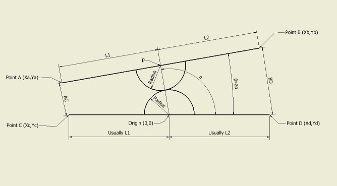
I thought the design was not linear, but it is. I created a spread sheet, if any of you are interested:
brazo5.xlsx
This is the diagram used for the excel file:
brazo5.xlsx
This is the diagram used for the excel file:

|
Re: New arm design for Simpson style printer. August 15, 2013 07:13PM |
Registered: 11 years ago Posts: 979 |
I was trying to get around to this diagram but you beat me to it. :-) Thanks! To visualize, the gear centers can be viewed as grounded. If you tilt one line the other tilts in the opposite direction. As long as you are talking about point pairs on these lines through the gear centers you are perfectly proportional.
|
Re: New arm design for Simpson style printer. August 15, 2013 07:28PM |
Registered: 10 years ago Posts: 145 |
 . Does that makes me quick too? Lol, I don't think so.
|
Re: New arm design for Simpson style printer. August 15, 2013 07:40PM |
Registered: 11 years ago Posts: 979 |
Of course you can be quick too. I am only quick out of necessity. I have promised to make 20 beta Simpsons so now I have to make it happen.
I am pretty much done with what beta Simpson needs so now you guys will have to agree on what the standard dumb joints will need to look like. I think a long of design should go into them because you will need so many of them. They need to be robust, accurate, cheap, and easy to assemble.
Check out the Gear Drive in action. 500mm/s!!!!!!
|
Re: New arm design for Simpson style printer. August 15, 2013 09:28PM |
Registered: 10 years ago Posts: 1,381 |
@nicholas
An impressive demonstration of the proportional gear drive joint.
What I like most about this drive is that it powers the arm in both directions, without backlash, and it doesn't use springs, or gravity. I'm going to adopt your design as it's a more elegant solution, tks!
Now I understand why you had the surface of the cam hanging below the arms. This was to allow for the string to attach to leverage points. I haven't seen any clear images of how the string is wound around the post.
I like the guitar gear idea, but the electric tuners will be heavy. I would take a look at the gearing that the nylon string guitars use. They typically use stamped metal housing, which is lighter, and plenty strong for this application, and nylon strings are slippery, so maybe they have some material/surface/anchoring issues worked out.
The spring will be 1.75 inch long at 5 lbs, that's kind of long, only thing shorter would be a torsion type spring mounted on a post. A hoop shaped spring would work too, some thing you would find on a ski boot latch. You may find that only the guitar tuner is required.
A2
|
Re: New arm design for Simpson style printer. August 15, 2013 11:03PM |
Registered: 11 years ago Posts: 979 |
|
Re: New arm design for Simpson style printer. August 16, 2013 09:37AM |
Registered: 10 years ago Posts: 145 |
I agree with the spring-tuner idea. BTW, the real part look impressive. Well, I think the first part you showed LOOKS more impressive, but the geared joint is impresive due to how simple it is, and thats the signature of a good design. Congratulations guys! and thanks Nick for taking the time to test and improve these crazy ideas.
|
Re: New arm design for Simpson style printer. August 16, 2013 11:16AM |
Registered: 10 years ago Posts: 5 |
Nicholas, any chance of putting the designs for some of the joints/arms you've played with on thingiverse? I know you probably want to wait and put an entire design, but although you've thrown away ideas like the double lamina compliant joint for your purposes it would be handy for others to have one ready to print and play.
|
Re: New arm design for Simpson style printer. August 16, 2013 12:03PM |
Registered: 11 years ago Posts: 979 |


Sorry, only registered users may post in this forum.