Sextupteron
Posted by nicholas.seward
|
Sextupteron July 25, 2013 04:35PM |
Registered: 10 years ago Posts: 979 |
I didn't know where to put this. I am going to assume this is the "Parallel Robots" sub-forum.
YOUTUBE CANDY!
INVENTOR FILES!
This is a variant of the Tripteron and the Quadrupteron. Following that naming scheme I had to call it the Sextupteron for a 6 degree of freedom version. The video has been shown to lead to confusion and drooling. Watch responsibly.
You could use this for 3D printing on surfaces that aren't flat, for an assembly robot, print with layers that aren't parallel to the xy-plane, printing extreme overhang, etc.
This is a full design. Every nut, bolt, board, bearing, and stepper has been accounted for. The only thing I fudged was the central hub and the ball connections. I think I will redesign it so that chrome steel balls snap into the end of the arms. I will also embed strong magnets directly in the plastic of the hub as it is printing. (Complete encapsulation.)
This style mechanism is protected under patent law and I don't control the patent. I hope to work a deal with the owners to open it up for open source development. If I understand the law, you can make one of these but you can't profit off of it. Yet.
Specification:
Outside Dimensions: 500mm cube
Print Dimensions: 325mm cube with the right arms and bigger if you tilt the hot end out to get past the tradition edge.
Allowable Tilt: With a redesign I should be able to get 45 degrees without sacrificing too much stability.
12 500mmx75mm identical pieces made from the flat stock of your choice.
8 unique plastic pieces.
45 plastic pieces
6 12mm x 510mm rods
12 LM12LUU bearings
8 608 bearings
6 185 tooth xl belts .1 pitch
120 M3x16
120 M3 nuts
6 M8x100
6 M8x60
12 M8 nuts
6 Nema17 steppers
etc.
The frame can be used for a 3DOF bot all the way up to a 6DOF bot. You could even do 2 independent 3DOF heads in the same space. You can see that you can mount a stepper in any orientation at any corner. The plastic pieces have rod seats built in so you can mount rods above any of the blue boards. There are also spots to mount an idler pulley everywhere you can mount a stepper.
I don't have time to build this monster and the electronics aren't really there yet but I would love for anyone else to take the idea and run. This was an idea in my head that I just had to get out or I would go crazy. Now that it is out, I now have 20 more ideas of what I could do with it. Arg!!!
BTW, the 3DOF version should be quicker to assemble than anything else out there and should be super cheap. (Not as cheap as Simpson or Wally but as cheap as a bot with rails can be.)
Edited 1 time(s). Last edit at 07/25/2013 04:35PM by nicholas.seward.
|
Re: Sextupteron July 25, 2013 06:17PM |
Nicholas,
The design seems sufficiently novel, but it has almost nothing to do with the Tripteron/Quadrupteron/Pentapreton family, and is therefore not even protected by the Tripteron patent (if I remember correctly). There are a lot of 6-PUS (prismatic-universal-spherical joint) parallel robots, so you have only replaced the U joints with a pair of R joints that have parallel axes. That said, your design is possibly great. For example, the robot has no link interferences, which is rare. This is something very positive!!!
Hmm, I need to think more about it.
Of course you don't need 6-DOF to do printing, but it's often cheaper to have six identical legs than five different ones. Otherwise, you can use a pentapod like this: [www.metrom.com].
Anyway, you deserve an honorary Master's degree. That's certain!
Keep on!
Ilian
[www.twitter.com]
|
Re: Sextupteron July 25, 2013 06:32PM |
Registered: 10 years ago Posts: 979 |
Okay guys, feel free to start a business selling Sextupterons. It is licensed under the GPL meaning that you just have to remain open source yourself.
@Ilian: I tried to make a 5DOF version and it could be done but it hurt me inside to break the symmetry. It would be a simple matter to slave two of the carriages together if you don't need any yaw. But why not? If you are able to control 5 steppers what is one more? In that situation you can add a 1D robot gripper and then do printing and assembly all together. It would also be quite humorous to be able to pick up a part after printing and fling it into a box. :-)
Edited 1 time(s). Last edit at 07/26/2013 04:01AM by nicholas.seward.
|
Re: Sextupteron July 26, 2013 01:39PM |
Registered: 11 years ago Posts: 4 |
|
Re: Sextupteron July 26, 2013 07:47PM |
Registered: 10 years ago Posts: 979 |
|
Re: Sextupteron July 27, 2013 07:33AM |
Registered: 10 years ago Posts: 979 |
If it was amazing before. Now there are no words.
YOUTUBE DIABETES INDUCING CANDY!
I reconfigured the middle arms and the hub to allow for greater travel and rotations. The build cube is up to 200mm and the allowable rotations are +/-58 degrees. That is a range motion of 116 degrees! No link collisions! I wouldn't have believed it if I didn't go through the animation frame by frame and view it from every angle to make sure this actually works. I also designed in some real like ball joints.
I updated the inventor files in the link at top of the page for the brave. (Mechanically this will be easy to build. The software will also not be so bad. I don't know enough to know how hard the electronics would be.)
Edited 2 time(s). Last edit at 07/27/2013 07:37AM by nicholas.seward.
YOUTUBE DIABETES INDUCING CANDY!

I reconfigured the middle arms and the hub to allow for greater travel and rotations. The build cube is up to 200mm and the allowable rotations are +/-58 degrees. That is a range motion of 116 degrees! No link collisions! I wouldn't have believed it if I didn't go through the animation frame by frame and view it from every angle to make sure this actually works. I also designed in some real like ball joints.
I updated the inventor files in the link at top of the page for the brave. (Mechanically this will be easy to build. The software will also not be so bad. I don't know enough to know how hard the electronics would be.)
Edited 2 time(s). Last edit at 07/27/2013 07:37AM by nicholas.seward.
|
Re: Sextupteron July 27, 2013 04:22PM |
Registered: 10 years ago Posts: 47 |
Nicholas
The magnets I used are .5" sphere Neodymium. I did quite a bit of experiment with different sets ,but this seems to be the best size for good holding power.
But I think the real trick is what I learned from (Berry Bot 3-D delta ) He suggested using this shoulder screw from McMaster Carr (91259a546 ) and using .5"mill on it to dimple the end. This combination works exceptionally well.
I'm a habitual builder and have a full machine shop that my current business is not really using. I'm going to have a look at the drawings for the Sextupteron , maybe I would be interested in putting this together.
Anything else I can do let me know I'm on the list for your Simpson
magnets
magnets
magnets
milling Shoulder Screw 1/4" Shoulder Diameter, 1-1/2" Length Shoulder, 10-24 Thread
Edited 2 time(s). Last edit at 07/27/2013 04:56PM by Dannydefe.
|
Re: Sextupteron July 27, 2013 04:37PM |
Registered: 10 years ago Posts: 979 |
|
Re: Sextupteron July 28, 2013 04:12AM |
Registered: 10 years ago Posts: 979 |
Video
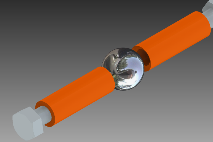
Here is an idea for a ball joint. You have some kind of 3D printed plastic part on each side of a spherical ball magnet. The bolts can almost but not quite touch the ball. The bolts can also just be loosely mounted. The magnet will keep them in position. I think I can generate more than the required force with these over-sized magnets. If this works it is a $40 solution. I found a $120 solution that used costly precision steel balls that were tapped and I still would have to buy the magnets.
Edited 2 time(s). Last edit at 07/28/2013 04:14AM by nicholas.seward.
|
Re: Sextupteron July 28, 2013 11:56AM |
|
Re: Sextupteron July 28, 2013 03:23PM |
Registered: 10 years ago Posts: 47 |
Here's another thought on the Magnet joint configuration. Just thinking... what if instead of trying to secure the sphere, we use the dimpled steel receptacles like I mentioned on both arms and the effective. I could imagine this would be threaded into the effector or Press-fit?
Of course these are not going to be off-the-shelf items , but it would be quite easy for my shop to make initial run . I have good connections with people with screw machines so we could knock off a couple of thousand in a heartbeat for others.
Also could you get me a copy of the files in different format for Solid works? .STL is cumbersome to get started in Solid works.
|
Re: Sextupteron July 28, 2013 04:04PM |
Registered: 10 years ago Posts: 979 |
|
Re: Sextupteron July 28, 2013 05:37PM |
Registered: 10 years ago Posts: 979 |
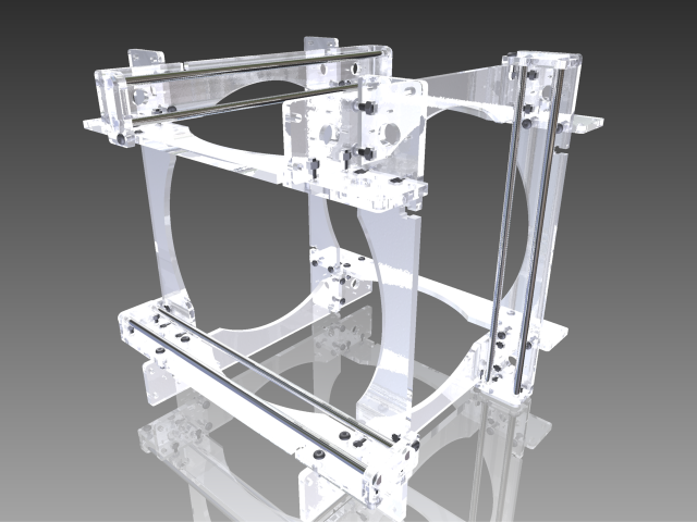
I am working on a laser cut version for Dan to build in the Ukraine. This is what I have so far for the frame.
3 unique parts so far.
10mm thick acrylic.
510mm rods
12 M8x25 (button head would be preferred but not required)
54 M8x30 (button head would be preferred but not required)
66 M8 nuts
Edited 2 time(s). Last edit at 07/28/2013 05:38PM by nicholas.seward.

3 unique parts so far.
10mm thick acrylic.
510mm rods
12 M8x25 (button head would be preferred but not required)
54 M8x30 (button head would be preferred but not required)
66 M8 nuts
Edited 2 time(s). Last edit at 07/28/2013 05:38PM by nicholas.seward.
|
Re: Sextupteron July 28, 2013 06:00PM |
Registered: 10 years ago Posts: 24 |
What about Parasolid, STEP, or IGES? I've never had much luck getting openScad files into SW.
I'm not sure about using a floating ball. At least I found that as the angle of the joint increased that lateral forces could easily separate it. That's why I ended up pouring ball seats even though the plain ring and ball is plenty enough to hold things normally (in my regular delta bot). During prints I would hear occasional chattering as the magnets would separate and then click back in place under load, the seats prevent them from moving laterally so the magnets can keep applying their full force. With a ball magnet and full cup seat I would expect you'll get more even force than a countersunk ring, but it's still going to want to slip. With two floating seats one of them will almost always be taking shear forces and it'll hurt even more as the seats pull away from the poles of the ball. If you fix the ball to one of the ends you can use a much smaller rigid mount and a larger seat on the floating side to preserve your range of motion.
I'm not sure about using a floating ball. At least I found that as the angle of the joint increased that lateral forces could easily separate it. That's why I ended up pouring ball seats even though the plain ring and ball is plenty enough to hold things normally (in my regular delta bot). During prints I would hear occasional chattering as the magnets would separate and then click back in place under load, the seats prevent them from moving laterally so the magnets can keep applying their full force. With a ball magnet and full cup seat I would expect you'll get more even force than a countersunk ring, but it's still going to want to slip. With two floating seats one of them will almost always be taking shear forces and it'll hurt even more as the seats pull away from the poles of the ball. If you fix the ball to one of the ends you can use a much smaller rigid mount and a larger seat on the floating side to preserve your range of motion.
|
Re: Sextupteron July 29, 2013 05:19AM |
Registered: 10 years ago Posts: 47 |
That's great you are doing design for acrylic. I have 3/8 (.343 Nominal )dark smoked acrylic in stock. I was asking for Solidwork friendly files because I would probably cut the first prototype Sextupteron on my Haas mill. I agree with the Post from (Extent), STEP, or IGES would work okay for my conversions. You can also include the Autodesk Inventor files, I've got some friends that might be able to translate into Solidworks.
|
Re: Sextupteron July 29, 2013 06:56AM |
Registered: 10 years ago Posts: 732 |
You can get steel balls at the end of a screw from DIN 71802 ball joints:
Here is a picture how does it look:
And even a non-angular version:
All these have only 18° angle, but if you connect it to a 3dPrinted plastic ball housing which will contain a cylindrical magnet then you get much better angles and the magnet pole will always be pointing to the centre of the steel ball, i.e. the sticky force will not change with angle.
Here is a picture how does it look:

And even a non-angular version:

All these have only 18° angle, but if you connect it to a 3dPrinted plastic ball housing which will contain a cylindrical magnet then you get much better angles and the magnet pole will always be pointing to the centre of the steel ball, i.e. the sticky force will not change with angle.
|
Re: Sextupteron July 29, 2013 07:02AM |
Registered: 10 years ago Posts: 979 |
|
Re: Sextupteron July 29, 2013 07:49AM |
Registered: 10 years ago Posts: 12 |
Maybe i didn't understand correctly, but there are threaded balls, i.e. used in piercing
Lots of sizes available
Also, there are lots of "inner thread balls"
Lots of sizes available

Also, there are lots of "inner thread balls"

|
Re: Sextupteron July 29, 2013 07:55AM |
Registered: 10 years ago Posts: 979 |
|
Re: Sextupteron July 29, 2013 08:15AM |
Registered: 10 years ago Posts: 979 |

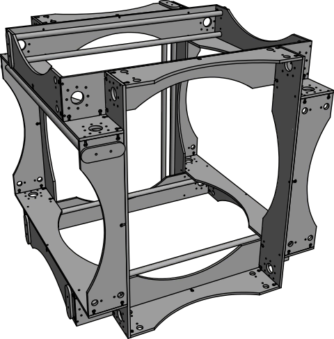
Please ignore all my previous post of files. I think I have hit upon a superior laser cut version that will be very tolerant of thin flat stock.
I am making it all parametric so you can change any of these parameters to meet your needs.
rod_length-500
rod_diamete-12
strut_width-75
flatstock_thickness-5
rod_spacing-50
rod_offset-25
nut_width-5.6
bolt_diameter-3.1
bolt_length -15
nut_height-2.5
bolt_spacing-55
I still have to add protruding alignment pegs.
Notice in the picture that I have some extra rails at the bottom. If you already are using 7 steppers why not 8? I want to have the table slide back and forth in addition to everything else. 500mm x 200mm x 200mm build volume. BAM!!!
Edited 1 time(s). Last edit at 07/29/2013 08:16AM by nicholas.seward.
|
Re: Sextupteron July 29, 2013 08:25AM |
Registered: 10 years ago Posts: 732 |
nicholas.seward Wrote:
-------------------------------------------------------
> How would I disassemble those to get the ball?
With enough force you can pull the ball screw out of the socket. I think DIN 71802 also specifies what is the minimum force to pull out the ball screw. You can study DIN 71802 specification for more details.
Notice the first picture. The steel socket has a groove to the right of the center of the ball. In that groove there is a spring (just a steel wire bent to an almost whole circle). If you pull strongly on the screw you can overcome the spring and pull out the ball screw. I have seen that some shops can deliver only the ball screws. I saw it somewher on the internet, but I do not know what are the minimum quantities and prices for ball screws only. I know it is possible to buy the whole ball joints in small quantities.
As for as full angle ball joint: I bought lately C13R (13mm ball diameter) here in EU and the price for one was about 2.5€. But you want a US located source. The biggest ball joints (I can quickly google) are C19R (19mm ball diameter). Maybe there are even bigger.
Maybe you can try these guys:
[www.tracepartsonline.net]
Looks like these guys can provide them:
T.E.A. Machine Components, Inc
2281-F Dabney Road
Richmond, Virginia 23230
USA
Or just google something better.
|
Re: Sextupteron July 29, 2013 08:30AM |
Registered: 10 years ago Posts: 732 |
|
Re: Sextupteron July 29, 2013 08:47AM |
Registered: 10 years ago Posts: 12 |
|
Re: Sextupteron July 29, 2013 08:59AM |
Registered: 10 years ago Posts: 979 |
|
Re: Sextupteron July 29, 2013 11:26AM |
Registered: 10 years ago Posts: 12 |
Found some other options
So called "Photo ball head", available at LHS, not sure about prices and materials
Also, you have McMaster-Carr with steel 3/4" balls..
[www.mcmaster.com]
And finally, take a look at Stud Mount Ball Transfer , like these
[www.vxb.com]
So called "Photo ball head", available at LHS, not sure about prices and materials

Also, you have McMaster-Carr with steel 3/4" balls..
[www.mcmaster.com]
And finally, take a look at Stud Mount Ball Transfer , like these
[www.vxb.com]
|
Re: Sextupteron July 29, 2013 10:16PM |
Registered: 10 years ago Posts: 979 |
IGES files attached! These are from the version I have on thingiverse. They are unfinished and will remain that way. I will get my act together some day and have a repository. However, I branched the machine 3 times on my very own machine.
I think I am going to scrap my hobby mill and use its NEMA23 motors to make a 1 meter cube version. I think I will go with a straight Tripteron setup using my latest framing. I can't wait to get my balls and magnets in the mail so I can officially test them to see if any of my cheap solutions will work.
I think I am going to scrap my hobby mill and use its NEMA23 motors to make a 1 meter cube version. I think I will go with a straight Tripteron setup using my latest framing. I can't wait to get my balls and magnets in the mail so I can officially test them to see if any of my cheap solutions will work.
|
Re: Sextupteron July 30, 2013 10:28AM |
Registered: 10 years ago Posts: 979 |
|
Re: Sextupteron July 30, 2013 03:54PM |
Admin Registered: 13 years ago Posts: 730 |
 If you haven't seen it already, you might like the
 |
Re: Sextupteron July 30, 2013 06:28PM |
Registered: 10 years ago Posts: 9 |
Just to point out, at least a few others are doing these magnetic joints with "regular" rostock and kossel designs. I think the consensus has been that it is much more cost effective to get cylindrical magnets and use stainless steel balls (not magnetic). I'm not clear how this affects the holding power of the joint, but the N52 cylindrical magnets I just received in the mail seem pretty awesome.
Just to elaborate and provide further info: (correct me if I'm wrong)
-you wouldn't want the sphere and magnet to touch directly, but to be very close
-scuffing up one part of the sphere allows for a better surface to jb weld (epoxy) the sphere to the tube or effector
-one guy used jbweld and coated the sphere in vasoline, then molded it to the shape of the sphere to make a nice connector
-you don't want to drill a magnet
-it is difficult to drill a stainless steel ball
I went with short cylinders so I could add more as I felt needed. I got 100 7/16in spheres for about $15, and 50 N52 magnets for $22. Probably overkill, but still much less than most of the other options discussed. It would be nice to find inexpensive threaded balls, but I've yet to find anything close to the pennies the non-magnetic stainless steel cost.
|
Re: Sextupteron July 31, 2013 06:27AM |
Registered: 10 years ago Posts: 979 |
I have purchased various chrome steel balls and various magnets (cylindrical and spherical). I look forward to hanging weights from them in the 90 degree and the 180 degree configuration to find the breaking force. I will be testing the following setups to find what is the cheapest adequate solution. Hopefully there is one. I will be print plastic tube to recieve the metal bolts or the cylindrical magnets. There will be 1 or 2 layers of plastic between the metal/magnet and the sphere. I will print a spherical cup into the end of the plastic tube.
[LEFT CYLINDER]/[CENTER SPHERE]/[RIGHT CYLINDER]
1) bolt/chrome steel/bolt (I don't think this one will work.)
2) bolt/magnet/bolt
3) magnet/magnet/magnet
4) magnet/chrome steel/magnet
I want option 4 to be the winner but we will see. I think 3 might suffer in the 90 degree position from the pole misalignment.
I really want to be able to generate enough holding force to be able to have a dremel attached. I will do the match before I think about that anymore.

Sorry, only registered users may post in this forum.