FLSUN I3 kit review
Posted by R.G.
|
Re: FLSUN I3 kit review December 03, 2016 11:50AM |
Registered: 7 years ago Posts: 34 |
Did some speculative thinking while messing with the 3d cad drawing of the FLSun in FreeCAD.
For stiffening and rigid-izing, the obvious points to start are the corners of the frame, the motor mounts, and the Y-axis rod mounts. The motor mounts and Y-axis mounts are fairly easy to replace with aluminum sheet in 1/8"/3.5mm or thicker. The simple way is to remove the old mount, lay it on a bit of aluminum sheet and use transfer punches to locate the holes after tracing the outline. Some drill time and some hacksaw time later you have an aluminum mount replacement. This can actually be done one at a time.
As for critical measurements, there are only a few. Fortunately, as my friend Jim says, that's why God made oval holes. The stepper motor mounting holes can be made oversize to adjust the Z-motor position to keep the distance between the Z-guide and leadscrews to match the printed X-axis carriers for the Z-parts.
Edit: the ebay aluminum offering market is confusing, but a piece of aluminum 6"x9" or bigger could be cut into three motor mounts and both front and back Y-axis holders. I found suitable pieces for under $20. Online Metals or Speedymetals might be cheaper. This was for 1/4"/6.35mm thick aluminum; oddly, the thinner 3/16"/4.5mm stock was more expensive for the same size. 1/8" was cheaper as expected.
To stiffen the Y-frame, one could cut lengths of 2"/50mm aluminum angle. Architectural angle has a sharp inner corner and will fit better. Four 2.5" or 63.5mm lengths of this would add "legs" on all four corners and screw-mount into the extrusions to stiffen the corners as the existing "feet" do not.
Another 2.5"/63.5mm length of 2x2 angle could be mounted on the inside of each of the Z-frame uprights to replace the inside corner casting supplied with the kit. This mounting would allow - and require! - a hole for the Z-axis guides to pass through it. It would also supply a place to mount a Z-rod flange clamp to hold the upper end of the Z-guides firmly. If the Z-leadscrews were replaced with longer ones, they, too would extend through the new angle bracket, and could be inserted through bearings to hold them in relative position, and could have GT-2 pulleys mounted on the ends to synchronize the two leadscrews' rotation, as well as to add a handwheel for manually setting Z with the motors off.
Edit: aluminum angle is very expensive on ebay. Online Metals has 2"x2" by 1/4" thick angle for $6.73 per foot plus about $20 shipping. Adding enough 1/4" plate to do the motor mounts costs ~$10, and adds nearly nothing to the the shipping, so all the aluminum could be bought new for under $40.00, if you don't have a local source, perhaps at scrap prices.
If anyone is interested, I can do sketches.
Edited 1 time(s). Last edit at 12/03/2016 01:02PM by R.G..
For stiffening and rigid-izing, the obvious points to start are the corners of the frame, the motor mounts, and the Y-axis rod mounts. The motor mounts and Y-axis mounts are fairly easy to replace with aluminum sheet in 1/8"/3.5mm or thicker. The simple way is to remove the old mount, lay it on a bit of aluminum sheet and use transfer punches to locate the holes after tracing the outline. Some drill time and some hacksaw time later you have an aluminum mount replacement. This can actually be done one at a time.
As for critical measurements, there are only a few. Fortunately, as my friend Jim says, that's why God made oval holes.
The stepper motor mounting holes can be made oversize to adjust the Z-motor position to keep the distance between the Z-guide and leadscrews to match the printed X-axis carriers for the Z-parts. Edit: the ebay aluminum offering market is confusing, but a piece of aluminum 6"x9" or bigger could be cut into three motor mounts and both front and back Y-axis holders. I found suitable pieces for under $20. Online Metals or Speedymetals might be cheaper. This was for 1/4"/6.35mm thick aluminum; oddly, the thinner 3/16"/4.5mm stock was more expensive for the same size. 1/8" was cheaper as expected.
To stiffen the Y-frame, one could cut lengths of 2"/50mm aluminum angle. Architectural angle has a sharp inner corner and will fit better. Four 2.5" or 63.5mm lengths of this would add "legs" on all four corners and screw-mount into the extrusions to stiffen the corners as the existing "feet" do not.
Another 2.5"/63.5mm length of 2x2 angle could be mounted on the inside of each of the Z-frame uprights to replace the inside corner casting supplied with the kit. This mounting would allow - and require! - a hole for the Z-axis guides to pass through it. It would also supply a place to mount a Z-rod flange clamp to hold the upper end of the Z-guides firmly. If the Z-leadscrews were replaced with longer ones, they, too would extend through the new angle bracket, and could be inserted through bearings to hold them in relative position, and could have GT-2 pulleys mounted on the ends to synchronize the two leadscrews' rotation, as well as to add a handwheel for manually setting Z with the motors off.
Edit: aluminum angle is very expensive on ebay. Online Metals has 2"x2" by 1/4" thick angle for $6.73 per foot plus about $20 shipping. Adding enough 1/4" plate to do the motor mounts costs ~$10, and adds nearly nothing to the the shipping, so all the aluminum could be bought new for under $40.00, if you don't have a local source, perhaps at scrap prices.
If anyone is interested, I can do sketches.
Edited 1 time(s). Last edit at 12/03/2016 01:02PM by R.G..
|
Re: FLSUN I3 kit review December 03, 2016 01:50PM |
Registered: 7 years ago Posts: 34 |
Here's a pic of some aluminum stiffening mods.
The four legs are 2.5" lengths of 2x2 aluminum architectural angle, as is the angle in the upper corner of the Z-frame.
The motor mounts are green, and the Y-axis mounts are ... um, pomegranite?
The five pieces in front of the frame are the size of the flat mounts, and can be cut from one 6" x 9" pieces of aluminum sheet.
I used 20x20mm cubes for the frame pieces instead of the more visually confusing actual extrusion as shown to the back of the frame.
Axes and rods as close as I can reverse-engineer them.
Edited 1 time(s). Last edit at 12/03/2016 01:57PM by R.G..
|
Re: FLSUN I3 kit review December 03, 2016 07:19PM |
Registered: 7 years ago Posts: 21 |
I've been busy with mine, today. I noticed that the X belt was loose again and found that the carriage is stressed with the grain to lock the upper X rod and it cracked letting it loose. Back to one of my other ideas, a clamp that sits on the upper X rod by the left carriage that holds the rod tight in the right carriage. I printed up the part, disassembled X and Z enough to get it installed and then adjusted. I like this a lot better than the dinky screw in the left carriage. I drew the part with tight tolerances on the 8mm rod. I inserted a 5/16th bit in the 8mm hole while it was still warm, and once cooled used it to ream the hole to final size. The hole for the screw was drilled into the part, not printed. I wanted it tight on the screw and a 9/64ths bit does the job.
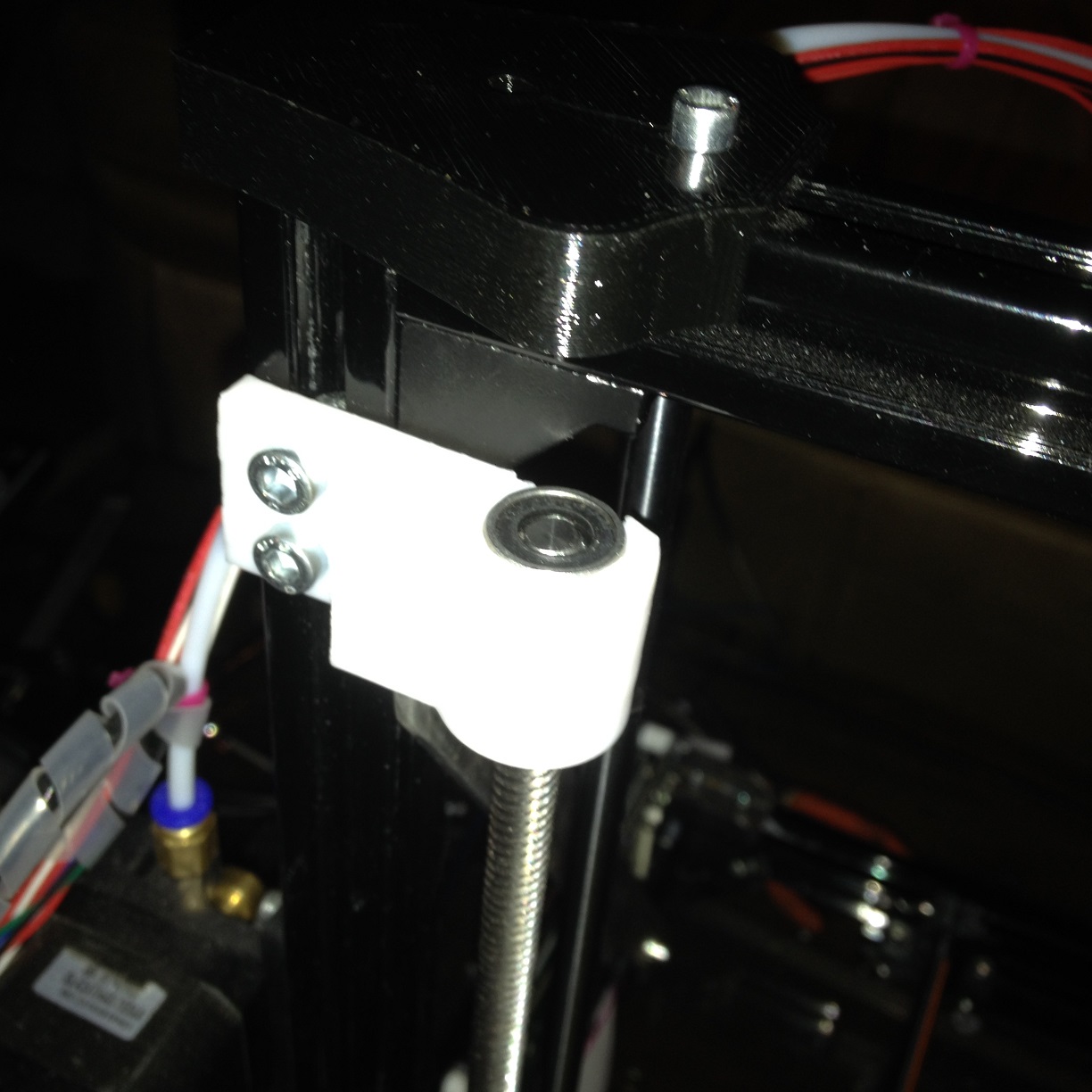
Looking for any other slop in this thing I found that the Z screws flopping at the top was still allowing some twist in the X cariages. Back to the drawing board. I came up with some brackets that use my leftover 24mm linear bearings to attach the top of the screws to the extrusion towers. I got my dimensions wrong on the first print but I figured it out once it bound. Re-drew and printed, then installed. No slop in the X now at all and the belt is super tight. They do take a smidge out of the total Z height possible but for me, at least, I haven't come close to pushing that limit and its a happy trade off.
I've attached some pics of the rod lock and the Z screw brackets and the STLs of the parts.
|
Re: FLSUN I3 kit review December 03, 2016 09:28PM |
Registered: 7 years ago Posts: 16 |
|
Re: FLSUN I3 kit review December 03, 2016 09:47PM |
Registered: 7 years ago Posts: 34 |
Very nice. I did have one question though. In the reading I did on linear bearings, I got that linear bearings should have substantially zero rotation of the shaft they slide on because the bearings are constrained to roll along the shaft, not across/around it. Something about dramatically reduced life if they did both rotation and linear motion.
If the idea is to just constrain the tops, would it work as well to put them in plastic bushing bearings or sintered bronze?
I was after much the same sort of thing by using the angle bracket under the top crossmember, and putting a clamp in for the Z-guide and a bearing for the Z-leadscrew.
If the idea is to just constrain the tops, would it work as well to put them in plastic bushing bearings or sintered bronze?
I was after much the same sort of thing by using the angle bracket under the top crossmember, and putting a clamp in for the Z-guide and a bearing for the Z-leadscrew.
|
Re: FLSUN I3 kit review December 03, 2016 10:22PM |
Registered: 7 years ago Posts: 21 |
I know linear bearings aren't supposed to rotate, but considering how slow the Z screws actually rotate I see them performing more as a guide than a bearing. If it does give issues I may eventually swap them for bronze. These were left over after swapping the Z bearings to 45mm units. I did just use them on the ACME rod. Its nominal OD is 8mm and the linear bearing moved across it quite well.
|
Re: FLSUN I3 kit review December 03, 2016 11:26PM |
Registered: 7 years ago Posts: 34 |
|
Re: FLSUN I3 kit review December 04, 2016 12:55AM |
Registered: 7 years ago Posts: 21 |

|
Re: FLSUN I3 kit review December 04, 2016 12:04PM |
Registered: 7 years ago Posts: 34 |
I read an article on applications of linear bearings from one of the major US bearing makers. It had some interesting comments.
One was that for good linear motion, no binding and long life, one of any group of guides should be rigidly fixed in position, and the other(s) fixed with a little compliance. The compliance let the one fixed guide be the thing that set the actual line of motion, the others merely supporting the motion. Apparently the tolerances on linear ball bearings are such that it's not normally possible to get two guides running parallel enough, except by accident, perhaps.
In the FLSun printer, perhaps ONE Z guide should be rigidly fixed, both ends, and the other soft-mounted, The leadscrews should probably be compliantly guided, especially if this can be done with a damping layer supplying the compliance.
Now for ... how... to do this.
|
Re: FLSUN I3 kit review December 05, 2016 03:56AM |
Registered: 7 years ago Posts: 16 |
|
Re: FLSUN I3 kit review December 05, 2016 10:33AM |
Registered: 7 years ago Posts: 34 |
The theory says to clamp one Z-guide solidly, and let the other have a bit of compliance. So modifying the Z bearing holder for one side would make sense.
I have the Z-guides converted into FreeCAD. You want me to send you an STL with one side a little looser for a rubber insert so you could try it?
I have the Z-guides converted into FreeCAD. You want me to send you an STL with one side a little looser for a rubber insert so you could try it?
|
Re: FLSUN I3 kit review December 11, 2016 01:33PM |
Registered: 7 years ago Posts: 14 |
Have anyone managed to update the firmware on these printers?
Mine came with a version of marlin that is a little older than1.0.1 bit newer than 1.0beta. The source code that came with the printer compiles and works fine, so I tried to copy the changes (pinouts and LCD settings) from the configuration file to the latest marlin but it won't work and nothing shows on the LCD.
I couldn't find the schematics of the Ramps 1.4plus and not sure if it uses the same pinouts as the normal ramps shield.
|
Re: FLSUN I3 kit review December 22, 2016 10:05AM |
Registered: 7 years ago Posts: 34 |
I'm fairly new to all this myself, so this may or may not help.
When you say that the version that came with the printer compiles and works fine, have you actually done the step of compiling the code that comes with the printer, and then loading that into the printer? I tried that, and found that the firmware image in my printer did not include the bootloader code that actually lets the code load from the Arduino IDE.
When you say that the version that came with the printer compiles and works fine, have you actually done the step of compiling the code that comes with the printer, and then loading that into the printer? I tried that, and found that the firmware image in my printer did not include the bootloader code that actually lets the code load from the Arduino IDE.
|
Re: FLSUN I3 kit review December 22, 2016 05:33PM |
Registered: 7 years ago Posts: 14 |
Yes, mine has the arduino bootloader, and I used the arduino IDE to flash the original firmware.
I have flashed mine a number of times now and it works great. I had issues with it at first but after many trials it worked and I am not sure how.
Try running your board from usb power, play with the reset jumper check the connections, try another machine, another operating system.... Those are the things that I have played with and now it works and I can use the arduino ide to complie and upload the firmware.
If you are sure your board doesn't have the bootloader then you will need to find the pins that can make up the ICSP connector and burn in the bootloader using any avr programmer like the cheap usbasp.
|
Re: FLSUN I3 kit review December 23, 2016 10:44AM |
Registered: 7 years ago Posts: 34 |
Yep, been there. The Exp 2 connector has all the icsp pins except reset. I soldered a pin onto the reset switch to connect to that. I flashed in the bootloader and then I started getting good IDE updates. Apparently there are several 'waves' of the controller board, some with, some without.
|
Re: FLSUN I3 kit review December 25, 2016 12:53AM |
Registered: 7 years ago Posts: 14 |
|
Re: FLSUN I3 kit review January 10, 2017 05:01AM |
Registered: 7 years ago Posts: 14 |
Quote
KingDWS
I see you had about the same issues I did. Mostly the head scratching for a few minutes trying to figure out if that's what they mean or am I misunderstanding type of problem. Those manuals are definitely not written by a native English speaker. The extruder calibration was the first thing I did as well and it was set to 60 and took 145ish to get 100 on mine as well. A few other guys and myself found the center of our build plates had a slight indentation in the center. Just enough to a make things be annoying and not stick well. Most ended up with using a glass plate to get around it.
One really good thing is a series of calibrations here on the forum. I just searched for calibration and found it. It goes through a bunch of different exercises to get everything from Temps to speeds closer. Really worth trying. That and if you have it printing go to Thingiverse and grab the files to print thumb wheels to use instead of those wing nuts. Much easier to get the bed set, that and a 8 thou feeler gauge instead of the paper (it's more stable than paper etc etc, I have a spare set cuz wife won't let me work on our m-class lol). The thumb wheels really make it easy to align the bed fast.
Hello guys, another fresh owner of FLsun kit here looking for help. I'm also a bit new to 3D printing. Finished assembling mine and made some trial prints, now it is time to fine tune.
KingDWS, would you mind to point me to those exercises? I would like to calibrate my extruder as well, however, i do not find it in settings (not by repetier and not by slic3r).
Edited 1 time(s). Last edit at 01/10/2017 05:01AM by rufinus.
|
Re: FLSUN I3 kit review January 11, 2017 03:41PM |
Registered: 7 years ago Posts: 1 |
I bought this kit just a few days ago and the assembly was completely painless (after I found out that there was additional assembly info in a subfolder). However, after connecting with Repetier Host, I only got the Z-axis and Y-axis engines to work (manual control). The X-axis remains at it's location, no matter what I do. I already checked the status for the limit switch, and M 119 says they're all open. I also switched the extruder engine with the X-axis engine, to ensure the engine is not broken, but the extruder engine is also not showing any activity if it's connected to the X-axis XH connector, so I'm worried that my board (my FLSUN kit was delivered with the Makeboard model pro) has some errors. Any idea how to debug?
|
Re: FLSUN I3 kit review January 11, 2017 06:13PM |
Registered: 7 years ago Posts: 16 |
The calibration stuff can be found at [reprap.org] and [reprap.org]
It looks a bit daunting but it just cuts down the calibration into a dozen or so steps or focused areas. Printing will be involved so have some filament handy! This is a bit easier when done while connected to Repetier. You could probably blast through this in a day but I would take it easy and make sure. I can't really add anything to what they get you to do other than after a bit go around and check your screws for tightness. These are small prints but they will still work the odd screw loose.
I started with Triffids but found that it wasn't addressing all the areas so I went through the other one as well. It is worth the time as you quickly go from blobs to pretty nice quality.
Edited 1 time(s). Last edit at 01/11/2017 06:30PM by KingDWS.
|
Re: FLSUN I3 kit review January 11, 2017 06:56PM |
Registered: 7 years ago Posts: 16 |
Hi Brink
First thing I would do is swap the motors onto the Y axis (Z has two motors so is bigger pain in butt) and make sure they all run.
Next check your connectors as I think you have a couple of the motor connectors in the wrong place. Use a piece of masking tape on the connector end around the wires so you can write down what it belongs to. It is worth doing and if you come back to sort out a new problem in a month or so when you have forgotten what goes where it REALLY helps then lol.
Make sure the driver boards are seated. Make sure the connectors from the motors are seated. These pin connectors are not great when exposed to vibration and if the connection is not vertical ie pins facing up then even the weight of the wire when it starts vibrating from movement will work the connections loose or just by brushing them with your hand etc. I have my controller board mounted vertical so the pins are on the horizontal axis and every few hours one of my Z connectors will work loose enough to make the motor sound like it isn't getting enough power (goes from quiet to a buzzy sound). The driver board connections are different but could have shifted during shipping or more likely assembly. These need to be seated so they are touching the base of the pin end connector on the board. If they are at any angle or you see exposed pins between the board and connector they are not seated correctly.
The extruder will not function until it comes up to temperature. So you can either power on the heater or issue a cold extrude command which is M308 via Repetier. Make sure you don't try to feed filament into the cold extruder so no filament installed or disconnect the feeder tube on the extruder end. After you send the M308 the extruder should function.
Did you set the current levels to the motors yet?
Also you can carefully try using autohome but probably better to just home the X axis. If it goes to home then you should have control of it after. Autohome tends to drive the Z axis into the print bed until you play with the limit switch and get it set. So trying the home from repetier on just the one axis makes for slightly less cringe worthy stops.
|
Re: FLSUN I3 kit review January 11, 2017 10:53PM |
Registered: 10 years ago Posts: 47 |
Latest update: Upgraded to Linear Guide Version. [www.3dprintersonlinestore.com]
|
Re: FLSUN I3 kit review January 12, 2017 03:26AM |
Registered: 7 years ago Posts: 14 |
Quote
KingDWS
The calibration stuff can be found at [reprap.org] and [reprap.org]
It looks a bit daunting but it just cuts down the calibration into a dozen or so steps or focused areas. Printing will be involved so have some filament handy! This is a bit easier when done while connected to Repetier. You could probably blast through this in a day but I would take it easy and make sure. I can't really add anything to what they get you to do other than after a bit go around and check your screws for tightness. These are small prints but they will still work the odd screw loose.
I started with Triffids but found that it wasn't addressing all the areas so I went through the other one as well. It is worth the time as you quickly go from blobs to pretty nice quality.
Thanks a lot! Will do the steps, right now doing some optimization, as my X-rod is already loose and the M3 screw is not holding it, so the belt tension is lost and there is a lot of play. Just got the fixation thing installed on the rod, similar as Duckmang, but out of aluminium, should be sturdier.
Also replaced Z linear bearings with 45mm version and fixed the left rod with some epoxy, as it was a bit loose in the acrylic "nest" at the bottom.
Hotend cooler is also replaced, as it was vibrating a lot and very loud.
Added some grease to guide screws, as they were making noise and right stepper was skipping steps, when extruder is at the bottom.
Next step is to fix at least one of the lead screws at the top, similar as Duckmang did, but with small bearing (16x5x8mm). Should help with skipping steps an squeaking noise, also precision should improve. After that will install part cooler for PLA prints and, hopefully, that should be it.
|
Re: FLSUN I3 kit review January 12, 2017 04:25AM |
Registered: 7 years ago Posts: 16 |
Wow sounds like someone ran over your kit with a forklift lol.
Usually when you see skipping steps that is belt tension or motor current. I tensioned mine by the frequency of the sound it makes when you twang it. You just need a microphone and any software to count the frequency.
I'm replacing the acrylic bits with actual metal lol. Still annoyed at the all metal kit being not quite so "all" metal. I have some 8 mm elastomeric pillow block bearings to mount on the rods on mine. I am debating if I will move the Z motors to the top of the gantry. On one hand it is easy to create a mount but the motor weight on top might make the gantry move more or more prone to.
I think my next printer is going to have a welded steel frame. Cheap and able to drive over without moving lol.
|
Re: FLSUN I3 kit review January 12, 2017 09:31AM |
Registered: 7 years ago Posts: 14 |
Well, it was printing OK first prints, but then the X rod got more and more loose, even though i have fixed it straight at the beginning with the screw. But continuous belt tension and extruder movement have quickly loosened it.This fixation concept is not good at all.
It got into skipping steps and lead screw biting into brass after i replaced the bearings and fixed left glide rod (Z) with epoxy. Which is logic, it is a lot sturdier now, and if the lead screw is not fixed at the top, it tilts and motor is struggling to rotate it. Greasing helped a lot, but i still like the idea of fixing at least one lead screw at the top.
You are very right about acrylic components, i have already noticed how the motor mounts are deformed just with the motor weight. Unfortunately, right now i have no possibility to replace them with metal, so be it. But i'm a bit annoyed as well, in particular with X rods.
Regarding your idea to put Z motors on top, in my opinion, it is not very good idea, as you will create reversed pendulum, which will be prone to movements in Y directions. Also putting the motors on one side of the vertical frame will deform it, slightly, but will.
|
Re: FLSUN I3 kit review January 12, 2017 01:13PM |
Registered: 7 years ago Posts: 38 |
Hey everyone!
I just received my FLSUN Prusa i3 yesterday (first printer) so I'm pretty new to all of this. I've got it all put together but seem to be missing the adapter for the Z motors to connect to the one connection on the controller board.
The pictures in the manual don't show the end very well, is it just a simple joiner for the two, or is there anything fancy that needs to be done? I'm trying to decide if I just splice the two together, make my own adapter, etc.
Thanks! Can't wait to get this thing up and running
|
Re: FLSUN I3 kit review January 12, 2017 01:18PM |
Registered: 7 years ago Posts: 16 |
|
Re: FLSUN I3 kit review January 12, 2017 01:20PM |
Registered: 7 years ago Posts: 38 |
Quote
KingDWS
There are two Z motor connections on the board so is just plug and play, no need to make anything. Just look at the picture of the board in the manual (pdf) that shows where everything goes.
Mine doesn't seem to have 2 connections, and the manual I have shows an adapter used to connect both motors to a single plug on the board. The only other motor plug I have is for another extruder.
|
Re: FLSUN I3 kit review January 12, 2017 05:08PM |
Registered: 7 years ago Posts: 14 |
Quote
Ynothna
Mine doesn't seem to have 2 connections, and the manual I have shows an adapter used to connect both motors to a single plug on the board. The only other motor plug I have is for another extruder.
Which board do you have? is it the ramps 1.4plus? (this one has 3 ports for the Z, and they are all the same, one in the regular location under the Z marking, and two vertically placed on its right side)
send a picture of your board if you are not sure.
Edited 1 time(s). Last edit at 01/12/2017 05:10PM by fadroid.
|
Re: FLSUN I3 kit review January 12, 2017 05:39PM |
Registered: 7 years ago Posts: 38 |
Quote
fadroid
Which board do you have? is it the ramps 1.4plus? (this one has 3 ports for the Z, and they are all the same, one in the regular location under the Z marking, and two vertically placed on its right side)
send a picture of your board if you are not sure.
It's a RAMPS 1.4 but I don't think it's a plus.
I didn't notice until now, but there are 4 pins a little below each motor connection (under the chips that are raised up). I'm not sure if those are extra or not.
Edit:
Here is a picture from the manual of the board with the adapter.
Edited 1 time(s). Last edit at 01/12/2017 05:57PM by Ynothna.
|
Re: FLSUN I3 kit review January 12, 2017 07:45PM |
Registered: 7 years ago Posts: 38 |
Got it working!
There is a variable in the Marlin firmware to turn on dual Z or Y steppers and use the next available unused extruder connection. Annoyingly, the variable was in the copy of the firmware they sent with the printer, just disabled, so there was never any need for the adapter. Oh well, both of my Z axis motors are working now. My X still isn't responding, baby steps.
In case anyone else comes across this and needs to do something similar, I found the details here:
Dual Z drivers setup


Sorry, only registered users may post in this forum.