Which rail size and car size for 2020 extrusions?
Posted by drmaestro
|
Which rail size and car size for 2020 extrusions? April 08, 2016 06:38AM |
Registered: 9 years ago Posts: 330 |
Hi,
I am looking at linear rail systems and there are many rail sizes and car sized available. I was wondering which rail size would be the easiest to mount to a 2020 aluminium profile (mounting along the profile for the Z axis) . The car should be smaller than 27 mm wide to be able to fit.
Thanks.
I am looking at linear rail systems and there are many rail sizes and car sized available. I was wondering which rail size would be the easiest to mount to a 2020 aluminium profile (mounting along the profile for the Z axis) . The car should be smaller than 27 mm wide to be able to fit.
Thanks.
|
Re: Which rail size and car size for 2020 extrusions? April 09, 2016 09:28PM |
Registered: 8 years ago Posts: 1,671 |
The one I picked up(IKO) is about 9.3mm wide track so it sits ok on the slot, it's only 240mm long so would like to get a longer one in future, if there was a slightly wider one I would like to try it, but finding them is the issue, so see what you can find then figure if you think it would fit. Carriage is very small with only 4x 3mm holes in, so throws up its own mounting issues.
|
Re: Which rail size and car size for 2020 extrusions? April 10, 2016 09:27AM |
Registered: 9 years ago Posts: 330 |
So, it is probably similar to this link (of course, this is a cheap Chinese version, I don't mean to compare it quality-wise but only size-wise). I was also thinking about this size but a real problem to consider is the M3 holes. All of the T slot nuts I have seen are M4 or M5, so how would you be able to mount it on the extrusions?
|
Re: Which rail size and car size for 2020 extrusions? April 10, 2016 09:59AM |
Registered: 11 years ago Posts: 5,780 |
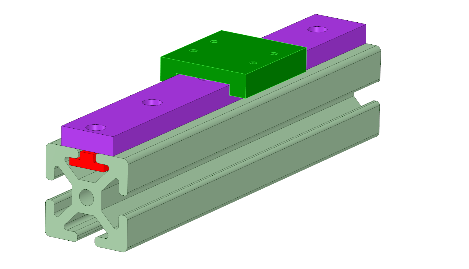
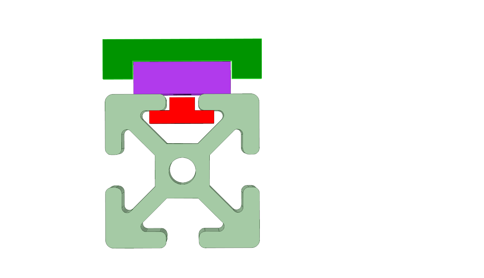
Try something like the red part here- it can easily be milled from a strip of aluminum, drilled and tapped for whatever size works with the linear guide you end up using. You might even be able to get away with a simple strip of aluminum (no milling), depending on the size of the T slot in the extrusion you're using. I wouldn't trust threads in 1 mm of aluminum to hold and not get stripped easily, but 3 or 4 mm might be OK. Using steel would let you go thinner than aluminum.
If you don't want to make a strip that runs the length of the rail you could make some small t-nuts using the same profile as the red part.
Ultra MegaMax Dominator 3D printer: [drmrehorst.blogspot.com]
If you don't want to make a strip that runs the length of the rail you could make some small t-nuts using the same profile as the red part.
Ultra MegaMax Dominator 3D printer: [drmrehorst.blogspot.com]
|
Re: Which rail size and car size for 2020 extrusions? April 10, 2016 01:24PM |
Registered: 9 years ago Posts: 330 |
Thanks for the idea of aluminum or steel strip. I think that could be the ideal solution. It shouldn't be too hard to model it but the real problem would be to know where to source it. I don't have access to a mill and I haven't been able to find an online site where you can upload an STL file and they send you a milled version. I'd assume there would be services in China for that but haven't found one. There may also be local providers but I am not sure they'd want to provide an economical solution for such a small job.
|
Re: Which rail size and car size for 2020 extrusions? April 10, 2016 01:33PM |
Registered: 11 years ago Posts: 5,780 |
In that case, just cut a strip from a piece of aluminum or steel, drill and tap holes. It doesn't have to be precise as long as it fits in the slot - it's just a clamp.
Are there any makerspaces in where you live? It should be pretty easy fabricate a part like this with basic tools, even without a mill.
There is this: [www.ebay.com]
Ultra MegaMax Dominator 3D printer: [drmrehorst.blogspot.com]
Are there any makerspaces in where you live? It should be pretty easy fabricate a part like this with basic tools, even without a mill.
There is this: [www.ebay.com]
Ultra MegaMax Dominator 3D printer: [drmrehorst.blogspot.com]
|
Re: Which rail size and car size for 2020 extrusions? April 10, 2016 03:27PM |
Registered: 8 years ago Posts: 1,671 |
I picked up M5 nuts before the rail came, but then I got a bag of 50 M3, very cheap, a little small but it works,
[www.ebay.co.uk]
the thing I have been thinking about more since you asked the question is, about the suitability for the Z, how your going to mount things to it, the load etc, I know the delta's have them, but with say a pursa style things could be tricky, I havent seen any examples of how things would be laid out, have you got something in mind.
Thats crazy stuff, stronger than normal 2020, looks like igus carriage would fit right over it.
Edited 2 time(s). Last edit at 04/10/2016 03:49PM by MechaBits.
[www.ebay.co.uk]
the thing I have been thinking about more since you asked the question is, about the suitability for the Z, how your going to mount things to it, the load etc, I know the delta's have them, but with say a pursa style things could be tricky, I havent seen any examples of how things would be laid out, have you got something in mind.

Thats crazy stuff, stronger than normal 2020, looks like igus carriage would fit right over it.
Edited 2 time(s). Last edit at 04/10/2016 03:49PM by MechaBits.
|
Re: Which rail size and car size for 2020 extrusions? April 10, 2016 04:47PM |
Registered: 9 years ago Posts: 330 |
Thanks for the link for the M3 nuts, I wasn't sure those things existed 
The aluminum extrusion with integrated rail is also a first for me! It is very logical but there might be some concerns on how straight it is. When I look at the picture, I can see that it isn't standing flat on its base, so probably not very straight.
You can see my Z axis elevator on the picture I've attached. I am planning on changing the parts that hold the LMe8UU bearings to rectangular structures with holes matching the linear guide's car's holes.The width should match the car's width. The depth will of course depend on the height of the whole rail assembly. I only have stl files, so, it could be tricky but I think it is achievable somehow. I didn't really think about loads, because I presumed that the main load is on the leadscrews and the rails would be there just to constrain the movement direction.
|
Re: Which rail size and car size for 2020 extrusions? April 10, 2016 05:31PM |
Registered: 8 years ago Posts: 1,671 |
|
Re: Which rail size and car size for 2020 extrusions? April 10, 2016 06:43PM |
Registered: 9 years ago Posts: 330 |
Quote
MechaBits
Are you going to use 4 rails 2 each side, thats going to be quite expensive, load should be fine with four, the potential for twisting & stresses if leadscrews get out of sync.
That was my plan. And yes, it will be expensive, so that's why this is my back-up plan before I try other things, like changing rod holders from plastic to metal and fixing them to the upper and lower horizontal extrusions instead of the vertical ones. I didn't really think about the lead screws getting out of sync part as this isn't something I have observed (although when I think that I have to recalibrate Z height every 3 to 4 prints, there probably is some desynchronization). Ideally, as would the_digital_dentist say, single motor driven Z axis would be a better solution (that's probably beyond my designing capabilities)
|
Re: Which rail size and car size for 2020 extrusions? April 10, 2016 07:13PM |
Registered: 8 years ago Posts: 1,671 |
|
Re: Which rail size and car size for 2020 extrusions? April 11, 2016 07:53AM |
Registered: 9 years ago Posts: 330 |
My leadscrews are too short and don't reach the top of the unit. I'd probaby need to design a piece to raise the motor. Then there is the problem on how to add a pulley to the leadscrew. There probably are GT2 pulleys with 8 mm bores which could be used for this purpose but I am not sure how you can fix it to a leadscew. Also, the leadscrew would need to be supported on the top part, otherwise the GT2 belt would flex it due to the tightness. I'd also have to remove the other motor and replace it with another leadscrew and a holder for that leadscew at the bottom.
Edited 1 time(s). Last edit at 04/11/2016 07:55AM by drmaestro.
Edited 1 time(s). Last edit at 04/11/2016 07:55AM by drmaestro.
|
Re: Which rail size and car size for 2020 extrusions? April 11, 2016 12:27PM |
Registered: 8 years ago Posts: 1,671 |
Yup, of course, as I said earlier change one thing and other things end up needing changing, they do do 8mm pulleys, I got a few, and it's just a screw or 2 to fix them, gouging into your lead, but as its not somewhere the nut will travel too it doesn't really matter.
Then its the question of which end bearings you choose dictates a few other positions, unless you have other custom parts to even things out, I'm not sure which printer you have, or if you really have to make all these changes, you can use an L bracket and rig a bearing into the hole or onto the surface, so things look similar to other side, a 22mm 8mm flange bearing could pop right in(but then you might need an 8mm drill stop or something to add a little extra support, or the other type in the housing can bolt onto it across the slots, but then the brackets not oriented the same as other side. Maybe better to try to use the printer to make some stuff to help sort out the issues, for a second build? parts dont need to be beautiful, just dimensionally correct.
Permutations are endless I've experimented with a couple of similar layouts, maybe they can help you decide what you want to do?
Probably would use direct couplers rather than flexi ones if needed.
Edited 1 time(s). Last edit at 04/11/2016 12:28PM by MechaBits.
Then its the question of which end bearings you choose dictates a few other positions, unless you have other custom parts to even things out, I'm not sure which printer you have, or if you really have to make all these changes, you can use an L bracket and rig a bearing into the hole or onto the surface, so things look similar to other side, a 22mm 8mm flange bearing could pop right in(but then you might need an 8mm drill stop or something to add a little extra support, or the other type in the housing can bolt onto it across the slots, but then the brackets not oriented the same as other side. Maybe better to try to use the printer to make some stuff to help sort out the issues, for a second build? parts dont need to be beautiful, just dimensionally correct.
Permutations are endless I've experimented with a couple of similar layouts, maybe they can help you decide what you want to do?


Probably would use direct couplers rather than flexi ones if needed.
Edited 1 time(s). Last edit at 04/11/2016 12:28PM by MechaBits.
|
Re: Which rail size and car size for 2020 extrusions? April 11, 2016 03:09PM |
Registered: 11 years ago Posts: 1,049 |
Why are you using crazy expensive extrusions and T-nuts
One can get a greenlee drill tap that will drill tap countersink in one operation
Match, drill, tap, and fasten your rails / plates when they are all squared up.
You can use a slotted hole if you really really need adjustment

One can get a greenlee drill tap that will drill tap countersink in one operation
Match, drill, tap, and fasten your rails / plates when they are all squared up.

You can use a slotted hole if you really really need adjustment
|
Re: Which rail size and car size for 2020 extrusions? April 11, 2016 03:42PM |
Registered: 8 years ago Posts: 1,671 |
your not wrong there, I only have one piece of 2020, the multiple sizes of nuts I needed, pushed the price up quite a bit, I doubt I would ever build a complete machine from extrusions, as nice as it looks, it still has issues, while its great for mounting stuff to it, it can also be a pain for some situations.
|
Re: Which rail size and car size for 2020 extrusions? May 21, 2016 06:10PM |
Registered: 9 years ago Posts: 330 |
Hi,
I'd like to give a little bit of feed-back on my project. I have found a local manufacturer for linear guides (I think they are Chinese rails which are re-branded). I wasn't sure about the size so I've bought 9 mm and 12 mm rails. It seems that 12 mm rails are better for 20x20 extrusions, because 9 mm rails tend to fall inside the opening on top of the extrusions, as they also measure 9 mm approximately.It might be possible to use them with very careful aligning but I find it unnecessary. To attach them, I will be using M3 T-slot nuts (that I've bought from the following link). The T-slot nuts do have some lateral play inside the groove of the extrusion, so to align them I push the rail to one side. This helps me to align the rail, even if it becomes slightly off-center (probably less than a mm). I have designed some Z cars compatible with the rails but haven't tested them yet, so right now I am printing them for this purpose (I have to be sure that everything is working as it should, as it will be difficult to correct errors after dismantling the printer to change the axis). I had some short extrusions so I tested the 12 mm rails with T-nuts on them. Here's a picture that demonstrates the rails on top of the extrusion:
Edited 1 time(s). Last edit at 05/21/2016 06:11PM by drmaestro.
I'd like to give a little bit of feed-back on my project. I have found a local manufacturer for linear guides (I think they are Chinese rails which are re-branded). I wasn't sure about the size so I've bought 9 mm and 12 mm rails. It seems that 12 mm rails are better for 20x20 extrusions, because 9 mm rails tend to fall inside the opening on top of the extrusions, as they also measure 9 mm approximately.It might be possible to use them with very careful aligning but I find it unnecessary. To attach them, I will be using M3 T-slot nuts (that I've bought from the following link). The T-slot nuts do have some lateral play inside the groove of the extrusion, so to align them I push the rail to one side. This helps me to align the rail, even if it becomes slightly off-center (probably less than a mm). I have designed some Z cars compatible with the rails but haven't tested them yet, so right now I am printing them for this purpose (I have to be sure that everything is working as it should, as it will be difficult to correct errors after dismantling the printer to change the axis). I had some short extrusions so I tested the 12 mm rails with T-nuts on them. Here's a picture that demonstrates the rails on top of the extrusion:

Edited 1 time(s). Last edit at 05/21/2016 06:11PM by drmaestro.
Sorry, only registered users may post in this forum.