Aluminium RepRap with leadscrews
Posted by samp20
|
Aluminium RepRap with leadscrews September 23, 2013 06:39PM |
Registered: 10 years ago Posts: 115 |
I thought I'd share my 3D printer design I've been working on which uses extruded aluminium and leadscrews. Looking around it seems very few people have tried to implement leadscrews (except this guy: http://www.thingiverse.com/jspark/designs). I have found these conversations though: forums.reprap.org and groups.google.com
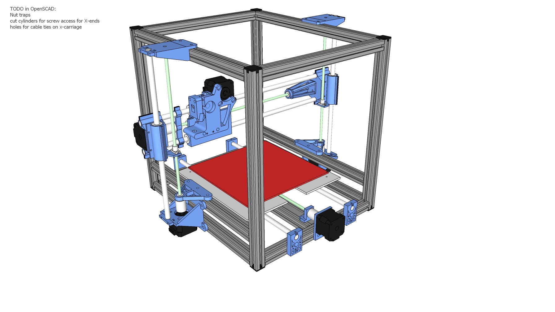
Attached is my ongoing attempt at designing this 3D printer. I'm still working on the X carriage/extruder and a few other small things. I would really appreciate any feedback good or bad you may have. This is the first time I've ever tried to design anything mechanical, so there's likely to be a lot of things I've overlooked. I'll be remodelling most if not all of the plastic components in OpenSCAD to get parametric hole dimensions, nut traps etc.
For sources of parts I've identified the following suppliers:
Leadscrews and nuts: www.rpmechatronics.co.uk. The largest lead I could find there was 9.53mm. I think that results in almost double the steps/mm of a typical belt driven reprap. I'm not sure if this is going to limit the maximum speed too much. Some calculations would help here.
Linear bearings/smooth rods: www.zappautomation.co.uk
Aluminium extrusion: aluminium-profile.co.uk
Even if this design turns out to be nothing I still aim to learn as much as possible from this. Sooner or later though I will want to replace my Prusa i2 with something more substantial that's capable of doing some light/moderate engraving.
|
Re: Aluminium RepRap with leadscrews September 27, 2013 06:43PM |
Registered: 10 years ago Posts: 115 |
Here's another update. I've attached some screenshots too for those who don't have sketchup installed.
The top Z rod supports and x-carriage have now been modelled. The extruder used is this one: www.thingiverse.com/thing:65939. I might look into supporting www.thingiverse.com/thing:76660 due to the four mounting points. Also I may be able to get extra range out of the z axis (currently 130mm) since the extruder motor won't collide with the top aluminium extrusion. The x and y both have 250mm currently, although limited by the 200x200mm heated bed.
The next stage is to finalise the x axis design, then begin creating parametric models in OpenSCAD. Also I still need a piece to attach the y axis leadscrew nut to the aluminium bed.
As before, all comments and criticism are welcome
|
Re: Aluminium RepRap with leadscrews September 29, 2013 10:58PM |
Registered: 11 years ago Posts: 1,049 |
Take a look at trinitylabs A1
[trinitylabs.com]
It uses 10 start 25mm pitch leadscrews , SIMO™ linear actuators (manufactured PBC Linear)
for X, Y axes and has a 12"x12"x12" print volume
Only 100 A1s were made currently and trinity labs is struggling
[trinitylabs.com]
It uses 10 start 25mm pitch leadscrews , SIMO™ linear actuators (manufactured PBC Linear)
for X, Y axes and has a 12"x12"x12" print volume
Only 100 A1s were made currently and trinity labs is struggling
|
Re: Aluminium RepRap with leadscrews September 30, 2013 07:42AM |
Registered: 10 years ago Posts: 115 |
Thanks for the link. I did take a look at trinitylabs, although was a bit put off by what I've read here http://forums.reprap.org/read.php?1,215025. Also the motivation for my design was to create something that required minimal tools to assemble and used relatively easy to source parts (e.g. 3d printed instead of machined).
As a side note I've realised my current design is a bit over engineered with the aluminium frame, so I'm working on simplifying that significantly
As a side note I've realised my current design is a bit over engineered with the aluminium frame, so I'm working on simplifying that significantly
|
Re: Aluminium RepRap with leadscrews October 02, 2013 07:31PM |
Registered: 11 years ago Posts: 1,049 |
"the motivation for my design was to create something that required minimal tools to assemble and used relatively easy to source parts"
Right? got to chuckle at that --- a new development --- early 3D printer development?
Hey you don't get CNC / 3D printer parts in a hardware store?
Hard to make a 3D printer with knife, fork and scissors.
I pointed you toward Trinitylabs A1 for leadscrew 3D printer design
Right? got to chuckle at that --- a new development --- early 3D printer development?
Hey you don't get CNC / 3D printer parts in a hardware store?
Hard to make a 3D printer with knife, fork and scissors.
I pointed you toward Trinitylabs A1 for leadscrew 3D printer design
|
Re: Aluminium RepRap with leadscrews October 03, 2013 04:05PM |
Registered: 10 years ago Posts: 115 |
Ah I do apologise. I think I misunderstood your post and thought you meant I should just buy theirs instead of trying to design my own (or is that still what you meant?).
I did take a look at the Trinitylabs A1 design, and was quite impressed. I've since reworked my design quite a bit, and is now based around the A1 and Smartroad's Dual-Struder Fabricator. Also the leadscrew pitch is now going to be 20mm. The previous 9.53mm was far too small. I've attached the .skp model, and some images below:
Here is the overview. The frame has been significantly changed since last time. I've also changed the leadscrews to ones from mooreinternational.co.uk. The standard nut is quite large however, so I might query to see if they sell smaller ones. I'm also planning on using hex pillars tapped into the aluminium base instead of screws/springs for bed levelling.
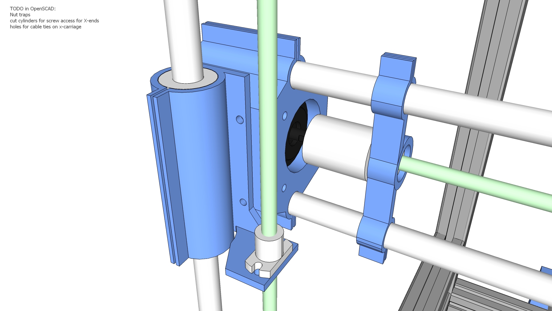
This is a detail of the x axis. I've decided to use derivative of RichRap's quick release x-carriage by PropsFactory on thingiverse. I've modified it to accept a leadscrew nut instead of belt clamps. The motor x-end is designed to accept a standard nema 17 stepper. I still need to create a support for the bearing on the x axis motor side. Same for the z axis motors. The bearings are there to take the load off the motor bearings.
I've neglected taking an image of the Y axis since it still needs modification for the larger leadscrew nuts. I might also try and bring the smooth rods closer to the aluminium extrusion or even touching similar to this MendelMax Minimal Y Rod Mount on thingiverse.
Edited 1 time(s). Last edit at 10/03/2013 04:11PM by samp20.
I did take a look at the Trinitylabs A1 design, and was quite impressed. I've since reworked my design quite a bit, and is now based around the A1 and Smartroad's Dual-Struder Fabricator. Also the leadscrew pitch is now going to be 20mm. The previous 9.53mm was far too small. I've attached the .skp model, and some images below:

Here is the overview. The frame has been significantly changed since last time. I've also changed the leadscrews to ones from mooreinternational.co.uk. The standard nut is quite large however, so I might query to see if they sell smaller ones. I'm also planning on using hex pillars tapped into the aluminium base instead of screws/springs for bed levelling.

This is a detail of the x axis. I've decided to use derivative of RichRap's quick release x-carriage by PropsFactory on thingiverse. I've modified it to accept a leadscrew nut instead of belt clamps. The motor x-end is designed to accept a standard nema 17 stepper. I still need to create a support for the bearing on the x axis motor side. Same for the z axis motors. The bearings are there to take the load off the motor bearings.
I've neglected taking an image of the Y axis since it still needs modification for the larger leadscrew nuts. I might also try and bring the smooth rods closer to the aluminium extrusion or even touching similar to this MendelMax Minimal Y Rod Mount on thingiverse.
Edited 1 time(s). Last edit at 10/03/2013 04:11PM by samp20.
|
Re: Aluminium RepRap with leadscrews October 09, 2013 06:22AM |
Registered: 11 years ago Posts: 544 |
have you seen those printed ball screws on thingiverse? I was thinking if you had some precise cutting tools, you could make grooves into the bearings so they could be used in a similar fashion, but on a leadscrew instead of a smooth rod.
edit: actually here, if you angle the bearings instead they can slip into the grooves of a multi start leadscrew. [www.thingiverse.com]
btw ball screws are like leadscrews with low friction and nearly no backlash.
Edited 1 time(s). Last edit at 10/09/2013 06:25AM by aduy.
edit: actually here, if you angle the bearings instead they can slip into the grooves of a multi start leadscrew. [www.thingiverse.com]
btw ball screws are like leadscrews with low friction and nearly no backlash.
Edited 1 time(s). Last edit at 10/09/2013 06:25AM by aduy.
|
Re: Aluminium RepRap with leadscrews October 09, 2013 12:18PM |
Registered: 11 years ago Posts: 1,049 |
I have followed the A1 for a while and have a friend that has one of the B2 models.
Lot of lessons learned in the Trinitylabs story
and the Goggletalk forum has a great amount of information
that can be incorporated into a design.
The A1 SIMO is a special mystery item
I like your open design of your rails / leadscrew axes
Lot of lessons learned in the Trinitylabs story
and the Goggletalk forum has a great amount of information
that can be incorporated into a design.
The A1 SIMO is a special mystery item
I like your open design of your rails / leadscrew axes
|
Re: Aluminium RepRap with leadscrews October 09, 2013 01:45PM |
Registered: 11 years ago Posts: 37 |
What is the attraction of a design with a bed that moves horizontally (Trinity Labs Aluminatus) vs vertically (Solidoodle)? As a print gets bigger, the former approach requires more and more power to accelerate the bed. Seems like the latter design is inherently better, at least in this one aspect.
|
Re: Aluminium RepRap with leadscrews October 10, 2013 01:32AM |
Registered: 11 years ago Posts: 544 |
|
Re: Aluminium RepRap with leadscrews October 12, 2013 04:58PM |
Registered: 10 years ago Posts: 115 |
Sorry for the delayed reply. The aluminium extrusion & fasteners have arrived, and I've been busy starting to assemble the frame. I've got the smooth rod and linear bearings on order, so they should arrive soon too. I'll create a page on the wiki now to make it easier to follow the build progress. Images of the design and the .skp file will be there too when I get back to my home PC (currently at my parent's for the weekend).
@aduy That ballscrew with linear bearings looks interesting. There's definitely some cost saving compared to ballnuts. Another option that may be worth investigating in the future is the threadless ball screw. Eventually I'll disassemble my prusa i2, so I'll have a few spare smooth rods to play with.
@cozmicray Thanks for the support and the googletalk forum. How well is your friend's B2 model working if you don't mind me asking?
A bit off topic, but it occured to me that I'm studying Electronic Engineering at university, yet decide to undertake a mechanical project as a hobby. Maybe I'm mad
@aduy That ballscrew with linear bearings looks interesting. There's definitely some cost saving compared to ballnuts. Another option that may be worth investigating in the future is the threadless ball screw. Eventually I'll disassemble my prusa i2, so I'll have a few spare smooth rods to play with.
@cozmicray Thanks for the support and the googletalk forum
. How well is your friend's B2 model working if you don't mind me asking?A bit off topic, but it occured to me that I'm studying Electronic Engineering at university, yet decide to undertake a mechanical project as a hobby. Maybe I'm mad
|
Re: Aluminium RepRap with leadscrews October 12, 2013 10:06PM |
Registered: 11 years ago Posts: 1,049 |
Guy with A1 is jon_bondy, he posted above
A1 was printing up a bunch of nautilus gears during Champlain Maker fair
and doing a great job
You might want to look at
Vermont Rapid Prototyping
[www.vermontrapidprototyping.com]
He has printed out a couple of guitar bodies on the A1
Sounds like a moose in heat most of the time.
He is looking for another A1.
If you can look at lessons learned or fixes/improvements to A1 on googletalk group
lots of great improvements
You can get a 10 start 25mm pitch Anti-Backlash Nut Fast Lead Screw
from Trinity --- expensive $100
Have Phun
|
Re: Aluminium RepRap with leadscrews October 17, 2013 07:15PM |
Registered: 10 years ago Posts: 115 |
A quick update. I've now got my build progress on the reprap wiki instead of attachments to this forum: http://reprap.org/wiki/ScrewRap. I still need to upload the STL files to github along with the skp design. A slightly out of date version can be found on the wiki here: Screwrap.skp. The differences are minor compared to my current latest.
I've got a set of smooth rods and linear bearings on order. They should arrive by next week. The major thing that's holding me up currently is waiting for parts to print. Unfortunately I work during most of the day, so only have a few hours in the evening to print. I could set one going in the morning, although the amount of messing around to get the print started would mean I'd need to get up a lot earlier. Also I need to find good slicer settings for ~3mm walls. Current settings cause quite large resonance in my printer when doing the infill. I might try out the frequency limiter setting in slic3r or increase the infill extrusion thickness.
Edited 1 time(s). Last edit at 10/17/2013 07:18PM by samp20.
|
Re: Aluminium RepRap with leadscrews October 17, 2013 10:36PM |
Registered: 11 years ago Posts: 1,049 |
The primary component -- the leadscrew and nut
Perhaps you should build up a leadscew / nut / slider and see how it works
I don't exactly know what screw/nut you intend to use
Will it give you right speed / accuracy
The only experience I have is watching the Trinitylabs A1 work
with SIMO and 10 start screw?
Perhaps you should build up a leadscew / nut / slider and see how it works
I don't exactly know what screw/nut you intend to use
Will it give you right speed / accuracy
The only experience I have is watching the Trinitylabs A1 work
with SIMO and 10 start screw?
|
Re: Aluminium RepRap with leadscrews October 18, 2013 03:31AM |
Registered: 10 years ago Posts: 115 |
I have had some experience of leadscrews, and probably wouldn't have undertaken this project if I didn't. At work we have some linear stages which are leadscrew driven. Those were 25mm pitch, 8 start, 6mm diameter. Looking at the specification on zaber.com they can reach up to 1000mm/s, which is more than enough. The motors used on the linear stage are also nema17s.
Edited 2 time(s). Last edit at 10/18/2013 07:49AM by samp20.
Edited 2 time(s). Last edit at 10/18/2013 07:49AM by samp20.
|
Re: Aluminium RepRap with leadscrews October 18, 2013 12:34PM |
Registered: 11 years ago Posts: 1,049 |
|
Re: Aluminium RepRap with leadscrews October 18, 2013 01:13PM |
Registered: 10 years ago Posts: 115 |
No I haven't considered double stack motors, although you do have a point. The ones I use at work are the standard size, although they're being run at 48V. They can be run from a 12V supply though. I'll give it a try when I next get the chance and see how it affects performance.
Thanks for the questions and all your input sofar. It's really helpful to have someone point out areas I've overlooked.
Thanks for the questions and all your input sofar. It's really helpful to have someone point out areas I've overlooked.
|
Re: Aluminium RepRap with leadscrews October 19, 2013 09:10PM |
Registered: 10 years ago Posts: 115 |
I thought I'd do some calculations whilst waiting to do a physical test. Mainly just to get a feel for what to expect.
To start with I'll set an arbitrary minimum force requirement of 30N. This is probably more than enough. From that, the leadscrew lead, and leadscrew efficiency I can calculate the minimum torque. T=(30N*20mm)/(2*pi*70%) = 13.6Ncm. The efficiency is an underestimate based on typical values seen from manufacturers. For drive I've found a single stack NEMA17 rated for 44Ncm at 1.68A. assuming torque is proportional to current (is this a correct assumption?) I'd get away with 30% of the current at 0.52A. From this and knowing the inductance/resistance I can make a rough estimation of the maximum speed by finding the time for the current to reach 0.52A with a 12V supply. The inverse of that time is approx 13kHz. From that divide by 200 steps per revolution then multiply by the 20mm lead. doing this results in a max speed of just under 1300mm/s. Not bad. Even if it is an absolute maximum there's still a good safety margin.
On the topic of leadscrews I'm expecting to be paid again within the next few days, so I can start thinking about buying them. They're not cheap however, so I'm still going to take my time before ordering.
|
Re: Aluminium RepRap with leadscrews October 29, 2013 07:24PM |
Registered: 10 years ago Posts: 115 |
A quick progress update. I'm in the progress of purchasing some leadscrews from [www.mooreinternational.co.uk]. They seemed the best price compared to a few other manufacturers. In total they will cost me just under £200. The leadscrews themselves are made by a company in Switzerland, although they have resellers across the world. Their website is here: [www.gewinde.ch]. This should be beneficial for anyone else wanting to build this 3D printer in the future.
I've also made progress on the wiki page. it can be found here: [reprap.org]. Below is the latest progress:

I have both the X and Z 10mm linear rods installed. I haven't kept track, although I'm sure my printer has been running for at least 24 hours in total for this build sofar. The feet themselves took 10 hours to print, although I was an idiot and started the print too late. Eventually I had to pause it so I could get some sleep!
Edited 1 time(s). Last edit at 10/29/2013 07:24PM by samp20.
I've also made progress on the wiki page. it can be found here: [reprap.org]. Below is the latest progress:
I have both the X and Z 10mm linear rods installed. I haven't kept track, although I'm sure my printer has been running for at least 24 hours in total for this build sofar. The feet themselves took 10 hours to print, although I was an idiot and started the print too late. Eventually I had to pause it so I could get some sleep!
Edited 1 time(s). Last edit at 10/29/2013 07:24PM by samp20.
|
Re: Aluminium RepRap with leadscrews December 15, 2013 03:39PM |
Registered: 11 years ago Posts: 334 |
I have been considering a screw design as well, part of the reason I was interested in screws was the print quality of the aluminatus. I have even looked into using PBC simo assemblies but they are way to expensive to be viable, so I am going a different direction. Recently I had a talk with another printer builder and he told me that I wouldn't gain much over belts as long as the rest of my printer was soundly designed. I am interested to see how your printer turns out, have you gotten any further?
WWW.ZATOPA.COM - Your Place for high quality 3D Printing Filament and accessories
WWW.ZATOPA.COM - Your Place for high quality 3D Printing Filament and accessories
|
Re: Aluminium RepRap with leadscrews December 15, 2013 05:46PM |
Registered: 10 years ago Posts: 115 |
Hi jzatopa,Quote
jzatopa
I have been considering a screw design as well, part of the reason I was interested in screws was the print quality of the aluminatus. I have even looked into using PBC simo assemblies but they are way to expensive to be viable, so I am going a different direction. Recently I had a talk with another printer builder and he told me that I wouldn't gain much over belts as long as the rest of my printer was soundly designed. I am interested to see how your printer turns out, have you gotten any further?
I have been making steady progress although I haven't uploaded anything for a while. I am now at the stage where all leadscrews are installed and the majority of the plastic parts have been printed. I'm waiting for some motor couplings to arrive so I can test it out (although the person I bought off only had 2 in stock, so I still need another 2). I did a quick test with a 3D printed coupling, although it was misaligned and thus caused too much friction. After loosening the motor so it can wriggle a little the performance was better. Haven't tested full speed yet though (need to change steps/mm).
The tasks left to do are:
- Install the motors and couplings. I have two 5mm to 5mm couplings arriving in a few days. I'll either find another two from somewhere or design some better plastic couplings. If I use plastic ones then they will be for the Z axis. Once the couplings arrive I'll do another test, but I'll set the steps/mm of my RAMPS board accordingly to make sure the motors can run fast enough. If this fails then I'll try increasing the current to the motors, and if that fails then increase the supply voltage to 24V after modifying my RAMPS controller. I also have the option to upgrade to some 44N.cm stepper motors. I took a look at the datasheet for the motors I have currently. They can keep a fairly constant torque with 24V, 1.68A up to around 5000pps half stepping. That's 250mm/s with my leadscrews. The 44N.cm motors can go up to 300-350mm/s.
- Drill holes in the aluminium base to mount it onto the Y bearings and leadscrew nut. This will take some time for the 12x12 grid I plan on drilling and tapping. The reason for this is to allow me to attach other things on at a later date. For example clamps could be screwed in to hold a PCB for milling. I may just do the important holes for now, and leave the rest to be marked out automatically by the printer.
- Buy some hex pillars to attach the heated bed to the aluminium base. The heated bed will be re-used from my Prusa i2.
- Install limit switches on all axes. I'm thinking of using hall effect sensors for this. I have suitable magnets already.
- Install extruder. I'm planning to reuse the one from my Prusa i2. Eventually I may replace the J-Head with a 0.35mm one.
- Install electronics. For now I'll use my existing RAMPS controller. In the future I may buy a SmoothieBoard or make a breadboarded version to experiment with.
As you can see I'll eventually have to disassemble my Prusa i2 to be able to finish the new printer. This is a bit risky if I end up needing to re-print a part. I don't want to have to buy a whole new set of electronics, motors and extruder though. I might ask someone at my local hackerspace if they can help print parts if I get stuck.
Edited 3 time(s). Last edit at 12/15/2013 05:51PM by samp20.
|
Re: Aluminium RepRap with leadscrews December 20, 2013 04:57PM |
Registered: 10 years ago Posts: 115 |
Another quick update,
My motor couplings arrived today, so I tested one out on the X axis. After changing the steps/mm the motor performs well up to the maximum 200mm/s my firmware allowed. The motor is only mildly warm to touch, so I can still increase the current some more if needed. I did notice the leadscrew was noisier than my belts, although the sound was amplified a lot by my wooden floor.
I'm going to wait until the new year to buy the other components needed since packages take a lot longer to arrive over the holiday period.
Here's some new photos I've added to the wiki page [reprap.org]:


|
Re: Aluminium RepRap with leadscrews December 24, 2013 08:00PM |
Registered: 11 years ago Posts: 565 |
|
Re: Aluminium RepRap with leadscrews December 27, 2013 02:04PM |
Registered: 10 years ago Posts: 115 |
Aluminium base plate has been drilled and all but 4 of the holes have been tapped (waiting for an M3 tap). I printed a drilling template onto an A3 sheet of paper and glued it onto the protective plastic. Here's some photos:
The base plate is for the Y axis. The heated bed PCB will attach with hex pillars screwed into the aluminium.
Edited 1 time(s). Last edit at 12/27/2013 02:06PM by samp20.


The base plate is for the Y axis. The heated bed PCB will attach with hex pillars screwed into the aluminium.
Thanks, I hope so too!Quote
Hux Flux
Nice Design i hope it will work
Edited 1 time(s). Last edit at 12/27/2013 02:06PM by samp20.
|
Re: Aluminium RepRap with leadscrews December 29, 2013 04:07AM |
Registered: 10 years ago Posts: 474 |
Nice-looking printer you might be a little low on power to drive it is a couple pics of mine using ballscrews .625 lead[i1333.photobucket.com][/I
MG][/URL]


|
Re: Aluminium RepRap with leadscrews December 29, 2013 10:00AM |
Registered: 10 years ago Posts: 115 |
Thanks. I am a little concerned about power, although a test I did a while ago on the X axis worked at 200mm/s. If the final machine doesn't work then I always have the fallback option of switching back to belts.Quote
cnc dick
Nice-looking printer you might be a little low on power to drive it is a couple pics of mine using ballscrews .625 lead
Your machine looks very professional. What pitch are you using on your leadscrews? Also I like how you've not taken any chances with the rigidity of the frame.
|
Re: Aluminium RepRap with leadscrews December 30, 2013 04:33AM |
Registered: 10 years ago Posts: 474 |
|
Re: Aluminium RepRap with leadscrews December 30, 2013 08:49AM |
Registered: 10 years ago Posts: 115 |
That's roughly 16mm pitch. It looks like your ballscrews are single start too. Mine are a lot more lightweight with 5mm diameter, 20mm pitch and 16 threads [www.mooreinternational.co.uk].
Edited 1 time(s). Last edit at 12/30/2013 08:50AM by samp20.
Edited 1 time(s). Last edit at 12/30/2013 08:50AM by samp20.
|
Re: Aluminium RepRap with leadscrews January 05, 2014 01:35PM |
Registered: 10 years ago Posts: 115 |
I've just been playing around with the Y axis motor from my old RepRap on the Y axis of my new one. The results are very promising: 300mm/s works well, 320-350mm/s works although a few steps may have been skipped, and 400mm/s stalls completely. I'll set the maximum feedrate to 280mm/s to allow a safety margin.
Here's the progress on the list of tasks I posted a while ago:
I've done as much as I can now without needing parts from my old printer. If all goes well I hope to be printing within the next few weeks.
EDIT: It's all done already! A dry run test proved that all the motors were working well, and the steps/mm were set correctly. I now need to get it printing parts to help me mount the control board and tidy up the wiring. I'll try and upload a video sometime soon of it's first print.
Edited 1 time(s). Last edit at 01/05/2014 07:10PM by samp20.
- Install the motors and couplings. All couplings are installed now.
- Drill holes in the aluminium base to mount it onto the Y bearings and leadscrew nut. Done.
- Buy some hex pillars to attach the heated bed to the aluminium base. Done. Just need to shorten a few screws for the hex pillars.
- Install limit switches on all axes. Printed switch mounts [github.com]. Reusing switches from my old printer for now until I buy some hall-effect sensors.
- Install extruder. I'm planning to reuse the one from my Prusa i2. Not done.
- Install electronics. Not done.
I've done as much as I can now without needing parts from my old printer. If all goes well I hope to be printing within the next few weeks.
EDIT: It's all done already! A dry run test proved that all the motors were working well, and the steps/mm were set correctly. I now need to get it printing parts to help me mount the control board and tidy up the wiring. I'll try and upload a video sometime soon of it's first print.
Edited 1 time(s). Last edit at 01/05/2014 07:10PM by samp20.
|
Re: Aluminium RepRap with leadscrews January 08, 2014 06:17PM |
Registered: 12 years ago Posts: 227 |

Sorry, only registered users may post in this forum.