Tripteron Implementation
Posted by Apsu
|
Re: Tripteron Implementation January 05, 2017 01:08PM |
Registered: 7 years ago Posts: 143 |
Quote
o_lampe
I just stumbled across an interesting bearing type called "cam follower cf5"
This might be a good solution for the z-axis dual rods?
Hrm. Interesting. Could be a few uses for similar parts, perhaps. I think the challenge is still what to mount any kind of bolt/axle in so it doesn't tilt or deform the mount, if the mount is plastic. It's tricky. An ideal situation would be to find an existing part that's commoditized and priced low, yet allows for metal-metal mating of a radial element.
I keep going back to strap hinges and looking for ones that are small enough and with a reasonable enough hole pattern they could be bolted to extrusions and form the joints. And made well enough they wouldn't have any play in them. I think that's the simplest all-metal commodity option that has the desired properties.
|
Re: Tripteron Implementation January 06, 2017 02:11AM |
Registered: 8 years ago Posts: 9 |
On a similar note I came across these bearings that are rated for moments. But I actually think the two bearings clamped towards each other gives you a similar setup. 
It sure would be nice if there was a 15mm version of this. You could just throw in some slippery washers or thrust bearings and be done with it.
Edited 1 time(s). Last edit at 01/06/2017 02:12AM by brazenrain.
It sure would be nice if there was a 15mm version of this. You could just throw in some slippery washers or thrust bearings and be done with it.
Edited 1 time(s). Last edit at 01/06/2017 02:12AM by brazenrain.
|
Re: Tripteron Implementation January 06, 2017 11:15AM |
Registered: 7 years ago Posts: 143 |
Quote
brazenrain
It sure would be nice if there was a 15mm version of this. You could just throw in some slippery washers or thrust bearings and be done with it.
Yes indeed! I've looked a lot at the die-cast and similar extrusion pivots, but they're really expensive. Well... they were really expensive, before I got to the point of getting joints machined which definitely costs more
 I'm not sure if you could find any made for 1515 and 2020 is pretty bulky, but this is what I had my eye on previously. I also don't know what kind of lateral load stiffness they have, but it's probably pretty good since they're designed for framing moving portions of large assemblies.
I also ran across these but they're for larger profiles
[www.minitecframing.com]
[www.minitecframing.com]
But man are they rated for high lateral loads and appear to be rock-solid!
|
Re: Tripteron Implementation January 06, 2017 02:49PM |
Registered: 7 years ago Posts: 143 |
Prototype machined joints came in!
Bolt holes are nice tight clearance fits, bearings fit great, tolerances and clearance are great, and the joint is, as expected, rock solid
I paid for these and asked the guy to make the other 10 for me, because for the rapid turnaround time and one-off nature this is perfect. Should have a machined assembly put together in a week or two looks like
|
Re: Tripteron Implementation January 06, 2017 10:43PM |
Registered: 8 years ago Posts: 1,671 |
|
Re: Tripteron Implementation January 07, 2017 08:38AM |
Registered: 7 years ago Posts: 143 |
Quote
MechaBits
Nice joints, musta cost a packet, looking forward to seeing them in action.
Yeah, me too! They were reasonably priced considering. About $65 for the pair, he was asking, but I did pay the guy extra because he did great work and treated me great. Forging that relationship is worth it. And really, cost of prototyping... I knew what I was getting into
Not going to be cheap, but I hope to A) have a kickass machine and  better inform the next design iteration. We'll find out!
|
Re: Tripteron Implementation January 07, 2017 12:47PM |
Registered: 8 years ago Posts: 9 |
|
Re: Tripteron Implementation January 07, 2017 01:41PM |
Registered: 7 years ago Posts: 143 |
Quote
brazenrain
In the meantime I'm looking into these. How do you think delteron will hold up with 10mm arms?
Oo interesting. I mean, it really depends on frame scale. In the 300ish XY frame member scale, and thus 300+ arm length scale, it seems like 15mm links is just big enough.
However, if those hinges can be low enough friction without a lot of slop (getting the nut tightness just right from the look of it?)... you can make a parallel 10mm arm system pretty easily. Because I assume the hinges are cheap, and the beams are cheap, so doubling up with some cross braces shouldn't be a big deal. In fact an approach like this might be the most reasonable in terms of cost/complexity/turnkey materials.
|
Re: Tripteron Implementation January 08, 2017 01:16AM |
Registered: 8 years ago Posts: 9 |
Here's what I have in mind for delteron's elbow joints:
This doesn't make the best use of having two arms as they're still right next to each other, but the cross-sectional bending stiffness is easily greater than a 15x15 extrusion. In return, torsional stiffness can be brought up to similar levels by closing out or trussing out the space between the beams with printed gussets. Reducing to a single beam for the 'forearm' should cut weight around the effector and simplify the interface.
Leaving the hinge anything less than tight will result in large amounts of backlash since the angular clearance gets magnified across the arm's length, so I'm going to try adding slippery washers to act as thrust bearings. The hinges are actually one of the more expensive parts at $3-4 per joint, similar to the m3x10mm shoulder bolts. The yellow part in the picture is a cheap M2 x 8mm brass standoff to clamp the joints to that should also assist with align the axes. It would be bottomed out against only the upper joint because the hinges are symmetric and don't have mirrored versions.
Parts are on their way but shipping the hinges from Germany could take up to 4 weeks... Meanwhile I'm going to try to cobble together a delta frame from a side table - a half finished project of mine which could serve as a test rig and eventual delteron.
Edited 1 time(s). Last edit at 01/08/2017 11:51AM by brazenrain.
|
Re: Tripteron Implementation February 03, 2017 12:55AM |
Registered: 8 years ago Posts: 9 |
Small update- I built assembled the aforementioned joint, but I overestimated how well aluminum-on-aluminum friction would hold. The beams themselves feel strong enough at 400mm total arm length, but the bolts won't stay put through a series of movements. It could be made to work by the right sequence of bracing, but then the alignment depends on the repeatability of printed plastic parts. For now I'm stowing the 10mm beams away- maybe for a sarrus linkage z-axis later on.
I also discovered that mcmaster had these for 20mm extrusions all along, which I might try next right after I push through to a working gantry for my cantilevered y-axis concept. I'm close to finishing the design without any printed parts but need to make sure it's stable enough running actual gcode to be worth carrying forwards.
I also discovered that mcmaster had these for 20mm extrusions all along, which I might try next right after I push through to a working gantry for my cantilevered y-axis concept. I'm close to finishing the design without any printed parts but need to make sure it's stable enough running actual gcode to be worth carrying forwards.
|
Re: Tripteron Implementation June 29, 2017 07:19AM |
Registered: 9 years ago Posts: 36 |
|
Re: Tripteron Implementation September 02, 2017 05:43AM |
Registered: 8 years ago Posts: 17 |
Hi Apsu,
I'm afraid that you've probably abandoned this project, but just in case...
In one of your early updates to this project you stated: "The angle between the actuators and the arm joint plane is something that can be tweaked as part of the engineering considerations. Larger angles give more resolution at the cost of less max Z height (actuators move up/down more for a given X/Y motion), while smaller give less resolution but gain Z height." Can you please explain that a little more? I'm having trouble visualizing which angles you are talking about, and how they affect Z-height.
Also, how does arm length play into this?
Anyway, sorry to see this thread go dormant. Lots of good info here.
Cheers,
Scotty
Edited 1 time(s). Last edit at 09/02/2017 05:44AM by scottyo.
|
Re: Tripteron Implementation September 02, 2017 12:23PM |
Registered: 7 years ago Posts: 143 |
Hey Scotty,
That was referring to the second design I began working on, where there's an angle the actuators are rotated with respect to the arm joints. The actuator arms have 3 joints -- actuator-arm, arm-arm, arm-effector. So really when I say "joint plane" I mean that those three joints are all aligned the same. However, how the two end joints attach to the actuator and the effector has a fixed angle like 30deg, for instance. You can adjust this angle a bit up/down around that value and it results in what I said. A smaller angle (closer to 0deg, or in-line with the arm joint plane) means that the same actuator motion (up/down) results in the same effector movement as a higher angle would with more actuator motion.
The tradeoff is a loss of resolution, because the relationship of the arm angle to resolution boils down to a simple ratio that varies only by that angle value. Likewise, higher angles give higher resolution but require more actuator motion for the same effector motion (higher ratio) -- practically this means you have less Z space to move in at the extreme top/bottom range, since you'll hit the end of the rails "sooner" to achieve the same amount of build space coverage. This is all assuming you're trying to maintain the same build area at every point in the build volume.
Hope that helps! I'm still around, even if not working on this anymore, so feel free (you or anyone else reading) to hit me up if you like. To be honest, I tend to jump between my hobbies every 6 months or so and this was a new one to me, so I dug in deep for awhile and now I'm back to music and gaming, but that doesn't mean I have no interest, I'm just not spending time on it right now
Edited 1 time(s). Last edit at 09/02/2017 12:24PM by Apsu.
|
Re: Tripteron Implementation September 02, 2017 12:23PM |
Registered: 10 years ago Posts: 979 |
Arm length needs to be just long enough to reach across the work volume. A smaller angle will allow the arms to be shorter. The flex of the arms is proportional to length^3 so you definitely want to minimize it.
ConceptFORGE
Wally, GUS Simpson, LISA Simpson, THOR Simpson, Sextupteron, CoreXZ
ConceptFORGE
Wally, GUS Simpson, LISA Simpson, THOR Simpson, Sextupteron, CoreXZ
|
Re: Tripteron Implementation September 02, 2017 01:30PM |
Registered: 8 years ago Posts: 17 |
Thanks - both of you!
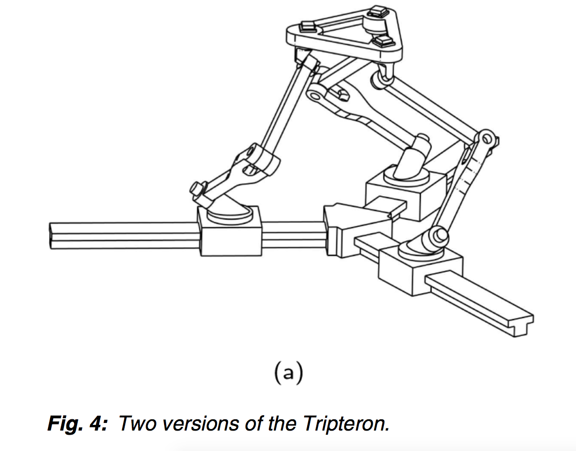
The application I am designing for will not require much z-height. Also I am looking at a variation of the "other" of the three implementations listed in the paper.
(The one attached below.) However, I am thinking I will probably incline the actuator rails a bit (and maybe flip it upside down - a shallow tetrahedron).
Thanks again,
Scotty
Edited 1 time(s). Last edit at 09/02/2017 01:39PM by scottyo.
|
Re: Tripteron Implementation September 02, 2017 01:44PM |
Registered: 8 years ago Posts: 17 |
|
Re: Tripteron Implementation September 14, 2017 03:06PM |
Registered: 8 years ago Posts: 32 |
|
Re: Tripteron Implementation October 05, 2017 10:16AM |
Registered: 8 years ago Posts: 42 |
|
Re: Tripteron Implementation December 28, 2017 04:02AM |
Registered: 6 years ago Posts: 2 |
Here is my tripteron trip.
Obviously, all the hard work was done by Apsu and there is not much to add, I really admire his design approach.
With my take on it, I decided to make it symmetrical with four bearings at the base actuator, three in the knee and two 604ZZ bearings in the end effector per arm.
The linear rails are 400mm but decided to make shorter arms due to flexing so print area is 320 by 320mm .
Most of the joints are printed in CFPLA also did try PC+ and ABS but as mentioned before, stiffness is your friend LOL. Also injecting epoxy resin into print does a great job making it stiff and strong.
Applied topology optimisation to win with the backlash while keeping low weight.TopOpt is mostly used for SLS printing but with a little fiddling was able to get pretty good results.
My observations are:
The support frames should be at least 2040.
The Z axis has to be on the lead screws.
The End effector should be as light as possible so is the arms should be made out of carbon fiber tubings.
You could also cheat the RepRap ideology and simply water jet the aluminum arms.
There should be two bearing blocks per X and Y axis, one is simply too wobbly due to it's lengh.
To sum things up I just did some first prints and it looks like it still needs work such as bed leveling, slicer settings, firmware etc. but I'm positive that tripteron could become a decent printer ,if not it could become an open source burger flipping bot.
Here are some videos not in chronological order, if anyone wants the files I will be posting them later on github , just drop me a line for the link.
MK2 one the first iterations(there was an MK1 but didn't bother filming it LOL) :
MK3 just a servo probe initial test
MK3 first print at 400mm/sec LOL
Obviously, all the hard work was done by Apsu and there is not much to add, I really admire his design approach.
With my take on it, I decided to make it symmetrical with four bearings at the base actuator, three in the knee and two 604ZZ bearings in the end effector per arm.
The linear rails are 400mm but decided to make shorter arms due to flexing so print area is 320 by 320mm .
Most of the joints are printed in CFPLA also did try PC+ and ABS but as mentioned before, stiffness is your friend LOL. Also injecting epoxy resin into print does a great job making it stiff and strong.
Applied topology optimisation to win with the backlash while keeping low weight.TopOpt is mostly used for SLS printing but with a little fiddling was able to get pretty good results.
My observations are:
The support frames should be at least 2040.
The Z axis has to be on the lead screws.
The End effector should be as light as possible so is the arms should be made out of carbon fiber tubings.
You could also cheat the RepRap ideology and simply water jet the aluminum arms.
There should be two bearing blocks per X and Y axis, one is simply too wobbly due to it's lengh.
To sum things up I just did some first prints and it looks like it still needs work such as bed leveling, slicer settings, firmware etc. but I'm positive that tripteron could become a decent printer ,if not it could become an open source burger flipping bot.
Here are some videos not in chronological order, if anyone wants the files I will be posting them later on github , just drop me a line for the link.
MK2 one the first iterations(there was an MK1 but didn't bother filming it LOL) :
Prined with ABS 400mm stroke from Peter Pozorek on Vimeo.
MK3 just a servo probe initial test
Tripteron Three point servo bed probing from Peter Pozorek on Vimeo.
MK3 first print at 400mm/sec LOL
First print ,wrong stepping on Z axis,bad slicer settings from Peter Pozorek on Vimeo.
|
Re: Tripteron Implementation December 30, 2017 03:35AM |
Registered: 8 years ago Posts: 5,232 |
Good to see it working. But the overkill in part count you mention above, will make it a rare beast.
I gave up on my project, because printing those critical parts is almost impossible. I tried round carbon tubes and cam-followers as bearings but the housings either were too loose or cracked from pressing in the bearings.
I gave up on my project, because printing those critical parts is almost impossible. I tried round carbon tubes and cam-followers as bearings but the housings either were too loose or cracked from pressing in the bearings.
|
Re: Tripteron Implementation December 30, 2017 01:51PM |
Registered: 6 years ago Posts: 2 |
Quote
o_lampe
Good to see it working. But the overkill in part count you mention above, will make it a rare beast.
I gave up on my project, because printing those critical parts is almost impossible. I tried round carbon tubes and cam-followers as bearings but the housings either were too loose or cracked from pressing in the bearings.
There is the number of quality high precision hinges that will take radial/ lateral load, cam-followers are just to hard fit/lineup as you mentioned.
|
Re: Tripteron Implementation July 26, 2018 03:40PM |
Registered: 8 years ago Posts: 1,671 |
Quote
Apsu
Quote
brazenrain
I also ran across these but they're for larger profiles
[www.minitecframing.com]
[www.minitecframing.com]
But man are they rated for high lateral loads and appear to be rock-solid!
I wouldnt mind some of these, but cant see a price do you have any idea how much & who has them?
|
Re: Tripteron Implementation July 25, 2019 02:31PM |
Registered: 7 years ago Posts: 143 |
Hello anyone still following this thread!
Man, it's been a while. I've had a lot of major life events happen that have kept me away but I haven't given up on the Tripteron development process, and I believe I'm in a place now where I can continue.
I also got a new job (one of those life events), and now work for a subsidiary of Autodesk(!), which means I have full access to fun tools like Fusion360, AutoCAD and Inventor. So I'm excited to get back into this.
To recap and expand on my plans:
And lastly, with regards to my original "as many parts printed, low cost, and easily obtained as possible" goal, I've decided to abandon it for now and just try to build the best orthogonal Tripteron I can. I achieved a working printer with worse parts than I have now, and a bed that wasn't even attached to the frame lol. My new goal is to make something as stiff, fast, and accurate as possible, without worrying about material/part choice, even if the BOM is > $1k, and then we can think about working backwards towards a cheap version with clever material/design choices to meet that goal.
But really, I'm just itching to make this thing become a Real Printer™ and feel like I've finally completed this project.
If anyone is still interested or has thoughts or ideas, feel free to chime in. It might still be a few days before I really get back in the swing of things, but you can expect pics and videos as per usual
Man, it's been a while. I've had a lot of major life events happen that have kept me away but I haven't given up on the Tripteron development process, and I believe I'm in a place now where I can continue.
I also got a new job (one of those life events), and now work for a subsidiary of Autodesk(!), which means I have full access to fun tools like Fusion360, AutoCAD and Inventor. So I'm excited to get back into this.
To recap and expand on my plans:
- I've got an Ender 5 with a bunch of upgrades as my new workhorse, so I can print new parts easily
- I have a full set of the machined Aluminum joints for the 1515 extrusion, minus the effector and shoulder brackets. I may get them machined as well, we'll see
- Rebuild the orthogonal Tripteron frame, and I may use 400mm rails and frame, since I have rails and pieces that long now
- Use a lead screw with anti-backlash nut for Z instead of a belt (requires redesigning the Z motor mount)
- Complete the full cube for the frame, for maximum stiffness and squaring
- Figure out mounts for a heated bed/fancy glass plate, like the new silicon/carbon ones that stick when hot and release when cool
And lastly, with regards to my original "as many parts printed, low cost, and easily obtained as possible" goal, I've decided to abandon it for now and just try to build the best orthogonal Tripteron I can. I achieved a working printer with worse parts than I have now, and a bed that wasn't even attached to the frame lol. My new goal is to make something as stiff, fast, and accurate as possible, without worrying about material/part choice, even if the BOM is > $1k, and then we can think about working backwards towards a cheap version with clever material/design choices to meet that goal.
But really, I'm just itching to make this thing become a Real Printer™ and feel like I've finally completed this project.
If anyone is still interested or has thoughts or ideas, feel free to chime in. It might still be a few days before I really get back in the swing of things, but you can expect pics and videos as per usual
|
Re: Tripteron Implementation July 30, 2019 01:10AM |
Registered: 7 years ago Posts: 143 |
So I've been thinking about this a lot lately, and I think that one of the difficulties I was facing even with the machined joints is that the bearings are the weakest point now. It occurred to me that I only went down the bearing route in the first place because I was trying to solve for printed joints. But if I get the machining route, there's some extremely simple and cheap to make part geometries that could be used instead.
For instance, using something very similar to a 3 or 4-hole flat plate designed for aluminum extrusion, bolted to the end of extrusion to form a fork, and similar on the other extrusion (to go outside the first fork), then a shoulder bolt or smooth shaft + low friction thrust washers/bushings could be used to fasten them together. Assuming there weren't premade parts that would work, these sorts of plates are extremely easy to machine so cost would be very low.
I may get some nylon or PTFE (or maybe even Igus) thrust washers and try a proof of concept with the simple 3-hole aluminum plates I have on hand, and report the results. But really, I don't think the bearing system is necessary and is an extreme overcomplication when not trying to use entirely printed parts.
|
Re: Tripteron Implementation July 30, 2019 02:25PM |
Registered: 5 years ago Posts: 3 |
|
Re: Tripteron Implementation July 31, 2019 05:08AM |
Admin Registered: 11 years ago Posts: 3,096 |
Quote
Apsu
So I've been thinking about this a lot lately, and I think that one of the difficulties I was facing even with the machined joints is that the bearings are the weakest point now. It occurred to me that I only went down the bearing route in the first place because I was trying to solve for printed joints. But if I get the machining route, there's some extremely simple and cheap to make part geometries that could be used instead.
For instance, using something very similar to a 3 or 4-hole flat plate designed for aluminum extrusion, bolted to the end of extrusion to form a fork, and similar on the other extrusion (to go outside the first fork), then a shoulder bolt or smooth shaft + low friction thrust washers/bushings could be used to fasten them together. Assuming there weren't premade parts that would work, these sorts of plates are extremely easy to machine so cost would be very low.
I may get some nylon or PTFE (or maybe even Igus) thrust washers and try a proof of concept with the simple 3-hole aluminum plates I have on hand, and report the results. But really, I don't think the bearing system is necessary and is an extreme overcomplication when not trying to use entirely printed parts.
What if you were to use long polymer bushings or some long version of this: [www.robotdigg.com]
I think that could take care of both having linear movement as well as rotational movement and have a tight diameter without much play? Am I missing important details why this is or isn't a good idea?
http://www.marinusdebeer.nl/
|
Re: Tripteron Implementation August 15, 2019 01:15PM |
Registered: 7 years ago Posts: 143 |
Quote
Ohmarinus
What if you were to use long polymer bushings or some long version of this: [www.robotdigg.com]
I think that could take care of both having linear movement as well as rotational movement and have a tight diameter without much play? Am I missing important details why this is or isn't a good idea?
I definitely think polymer bushings are a great way to go, and in fact that's where I'm focusing right now. I'm going to make another post in a sec with an update on where I'm at, which does indeed include polymer bushings and much simpler joints.
|
Re: Tripteron Implementation August 15, 2019 01:48PM |
Registered: 7 years ago Posts: 143 |
Hey folks, sorry for the delays, got hit with a bunch of work stuff and took longer to make some progress in redesign work.
I also have an update on the patent situation. I'm in talks with the University that holds the patent on obtaining a license, and I likely will be able to obtain one for the purpose of a small startup with an eye towards being legally able to sell kits or completed printers. I'm not trying to advertise and won't, but I think I can make a viable product with my current development direction so I figured I'd try to figure the legal side out.
In addition, I have learned that although US Patent Law explicitly states that making a patented device without a license -- even for personal use -- isn't allowed, there is actually court precedent that's long been accepted that there is an exception for research, personal amusement, or philosophical inquiry (Research Exemption). That's why universities can use patented ideas to further their own research and face no repercussions. Which means that legally speaking, we're all in the clear for purely DIY personal use, so long as it doesn't benefit your "legitimate business". So if you make one for your printing business, that's not allowed, but just for your personal non-commercial use or research, you're fine.
Ok with that out of the way, as I mentioned above, I'm redesigning my approach to the arm link assembly, starting with aluminum as a prototype material, but I believe carbon fiber and possibly some reinforced engineering plastics might work as well.
Here's a short video of the idea I am playing with currently. The links are solid pieces, and identical, with right angle joints for proper clearances, and are basically I-beams with tongue/fork ends. This increases their width substantially and are pocketed to decrease weight where possible.
The joint design idea is to press-fit Igus polymer flanged sleeve bearings (like these) into the tongues, and then use a steel dowel pin or possibly shoulder bolt to secure the forks into the tongues. I confirmed with Igus that the flanges can work as thrust washers against the flange/fork mating surfaces, so compressing them together should work great for this low RPM/low load application.
I also found that another research team at the University of California had the same idea around the time Gosselin did for the Tripteron, and built a prototype/published some papers on it. They also applied for a patent but it seems it was denied, so presumably they filed too late. Hard to say who came up with it first or if they did independently, these are all robotics professors who share a lot of information.
Anyhow, looking at their construction design gave me some ideas and led to my current approach. This is a good example image I pulled from Prof. Tsai's old page which I found on archive.org.
Here's a render of the link design so far .
I'm also exploring the idea of having an effector platform that can accept different tool inserts -- a manual tool-changer, in essence -- as well as having adjustable shoulder brackets to mount onto plates attached to the linear rail carriages, for adjusting the shoulder offset from the frame, as well as using different mounting plates for different kinds of linear bearing systems.
Last bit to talk about is the dual Z arms in the video above. I modeled it up to see if the clearances of all the links would work, and as you can see it works great. The benefit of a dual Z linkages is that the gravity load would be shared, which would further increase stiffness and ideally improve Z speed and accuracy. Now, for a 3D printer, that might be overkill, but again, considering having a swappable toolhead has me thinking about light duty CNC applications being possible as well. Pen plotting, engraving, soft material carving, etc. A dremel or small spindle mount would be relatively easy and in that scenario, higher Z speed and stiffness is a benefit.
Once I get some prototype parts made and get the mechanism hooked up and moving again I'll post another big update. And this time I have dc42's IR sensor working and a Duet2 WiFi board ready to go, so I'm looking forward to making use of it all!
I also have an update on the patent situation. I'm in talks with the University that holds the patent on obtaining a license, and I likely will be able to obtain one for the purpose of a small startup with an eye towards being legally able to sell kits or completed printers. I'm not trying to advertise and won't, but I think I can make a viable product with my current development direction so I figured I'd try to figure the legal side out.
In addition, I have learned that although US Patent Law explicitly states that making a patented device without a license -- even for personal use -- isn't allowed, there is actually court precedent that's long been accepted that there is an exception for research, personal amusement, or philosophical inquiry (Research Exemption). That's why universities can use patented ideas to further their own research and face no repercussions. Which means that legally speaking, we're all in the clear for purely DIY personal use, so long as it doesn't benefit your "legitimate business". So if you make one for your printing business, that's not allowed, but just for your personal non-commercial use or research, you're fine.
Ok with that out of the way, as I mentioned above, I'm redesigning my approach to the arm link assembly, starting with aluminum as a prototype material, but I believe carbon fiber and possibly some reinforced engineering plastics might work as well.
Here's a short video of the idea I am playing with currently. The links are solid pieces, and identical, with right angle joints for proper clearances, and are basically I-beams with tongue/fork ends. This increases their width substantially and are pocketed to decrease weight where possible.
The joint design idea is to press-fit Igus polymer flanged sleeve bearings (like these) into the tongues, and then use a steel dowel pin or possibly shoulder bolt to secure the forks into the tongues. I confirmed with Igus that the flanges can work as thrust washers against the flange/fork mating surfaces, so compressing them together should work great for this low RPM/low load application.
I also found that another research team at the University of California had the same idea around the time Gosselin did for the Tripteron, and built a prototype/published some papers on it. They also applied for a patent but it seems it was denied, so presumably they filed too late. Hard to say who came up with it first or if they did independently, these are all robotics professors who share a lot of information.
Anyhow, looking at their construction design gave me some ideas and led to my current approach. This is a good example image I pulled from Prof. Tsai's old page which I found on archive.org.

Here's a render of the link design so far .

I'm also exploring the idea of having an effector platform that can accept different tool inserts -- a manual tool-changer, in essence -- as well as having adjustable shoulder brackets to mount onto plates attached to the linear rail carriages, for adjusting the shoulder offset from the frame, as well as using different mounting plates for different kinds of linear bearing systems.
Last bit to talk about is the dual Z arms in the video above. I modeled it up to see if the clearances of all the links would work, and as you can see it works great. The benefit of a dual Z linkages is that the gravity load would be shared, which would further increase stiffness and ideally improve Z speed and accuracy. Now, for a 3D printer, that might be overkill, but again, considering having a swappable toolhead has me thinking about light duty CNC applications being possible as well. Pen plotting, engraving, soft material carving, etc. A dremel or small spindle mount would be relatively easy and in that scenario, higher Z speed and stiffness is a benefit.
Once I get some prototype parts made and get the mechanism hooked up and moving again I'll post another big update. And this time I have dc42's IR sensor working and a Duet2 WiFi board ready to go, so I'm looking forward to making use of it all!
|
Re: Tripteron Implementation August 16, 2019 11:40PM |
Registered: 7 years ago Posts: 143 |
Welp, turns out, even for shops that specialize in small runs of custom parts, these pieces are going to be extremely expensive to do in milled aluminum.
I'm investigating an alternative approach right now, using a US vendor called 80/20. They have a variety of awesome products centered around aluminum extrusion, and although they do have some common metric sizes like 2020, they mostly deal with imperial sizes. This is important to the discussion because while I've known about them for many years, and have a bunch of their 2020 extrusions, I wasn't able to try out some of their specialty components as they're only made in the imperial sizes. So I decided to rethink everything from the start and see what they had to offer, and found their pivots to actually be really awesome.
So here's what I'm thinking. I can use arm links made of 1020 (1" x 2") extrusion, and use one of the pivots, to create a joint like this:
These pivots are all aluminum, have self-lubricating bronze sleeve bearings, shoulder bolts, and 2 thrust washers to clamp the pieces together. There's a very large radius of surface contact and I suspect given the geometry and materials and joint design, it's going to be extremely rigid, especially on a profile that's nearly 51mm wide (2"). That's more than twice as wide as my 2020 joints, and no ball bearing play to try to preload against.
Here's a cross-section of the pivot:
Then I started looking around for other components that I could use to fashion into shoulder and wrist connectors, and I found these amazing self-lubricating creatures:
They even make shims to put under the sliding polymer fixtures to adjust their fit. I'm not sure if they'll be strong enough in the directions I would need them in, but I think I'm going to get one to try out, and enough 1010 profile to build a frame out of, because if it works it would be an amazing low profile linear bearing setup without needing a rail and ball-bearings. Also no need to try to match up rail and frame lengths or do any custom cutting, as well as the hit-or-miss quality of buying cheap MGN rails. I've gotten a few with pretty messed up carriages/balls, so it'd be great to go the polymer route if possible.
A full frame of 18" 1010, 8 links of 10" 1020 (dual Z towers), 12 1020 pivots, and 4 1010 linear slides would cost $537.28, which is twice as expensive as the printed version, yes, but has a really strong chance of working extremely well with easy to assemble, off-the-shelf parts.
I should get the pieces to test the joints in the next few days, so we'll see how well the pivots perform, as that's the most important part of the whole equation. If they work well enough, I will grab a linear slide to test, and ultimately start designing an effector that can mount to the pivots.
Edited 1 time(s). Last edit at 08/16/2019 11:41PM by Apsu.
I'm investigating an alternative approach right now, using a US vendor called 80/20. They have a variety of awesome products centered around aluminum extrusion, and although they do have some common metric sizes like 2020, they mostly deal with imperial sizes. This is important to the discussion because while I've known about them for many years, and have a bunch of their 2020 extrusions, I wasn't able to try out some of their specialty components as they're only made in the imperial sizes. So I decided to rethink everything from the start and see what they had to offer, and found their pivots to actually be really awesome.
So here's what I'm thinking. I can use arm links made of 1020 (1" x 2") extrusion, and use one of the pivots, to create a joint like this:

These pivots are all aluminum, have self-lubricating bronze sleeve bearings, shoulder bolts, and 2 thrust washers to clamp the pieces together. There's a very large radius of surface contact and I suspect given the geometry and materials and joint design, it's going to be extremely rigid, especially on a profile that's nearly 51mm wide (2"). That's more than twice as wide as my 2020 joints, and no ball bearing play to try to preload against.
Here's a cross-section of the pivot:

Then I started looking around for other components that I could use to fashion into shoulder and wrist connectors, and I found these amazing self-lubricating creatures:


They even make shims to put under the sliding polymer fixtures to adjust their fit. I'm not sure if they'll be strong enough in the directions I would need them in, but I think I'm going to get one to try out, and enough 1010 profile to build a frame out of, because if it works it would be an amazing low profile linear bearing setup without needing a rail and ball-bearings. Also no need to try to match up rail and frame lengths or do any custom cutting, as well as the hit-or-miss quality of buying cheap MGN rails. I've gotten a few with pretty messed up carriages/balls, so it'd be great to go the polymer route if possible.
A full frame of 18" 1010, 8 links of 10" 1020 (dual Z towers), 12 1020 pivots, and 4 1010 linear slides would cost $537.28, which is twice as expensive as the printed version, yes, but has a really strong chance of working extremely well with easy to assemble, off-the-shelf parts.
I should get the pieces to test the joints in the next few days, so we'll see how well the pivots perform, as that's the most important part of the whole equation. If they work well enough, I will grab a linear slide to test, and ultimately start designing an effector that can mount to the pivots.
Edited 1 time(s). Last edit at 08/16/2019 11:41PM by Apsu.
|
Re: Tripteron Implementation August 17, 2019 02:26AM |
Registered: 7 years ago Posts: 143 |
Welp, I decided to go ahead and model it up. I was able to connect everything with literally just the parts from 80/20, which is kind of amazing. I got a clever idea about using a 2"x2"x2" extrusion for the effector and with a little more mounting cleverness, it works shockingly well. I also reduced the outer frame lengths to 16" instead of 18", to avoid Z arm jackknifing.
Here is a video link and here is the A360 3D viewer link. I know the navigation is a little messy, but I'm trying to show all the angles, some of the joint interference spots that need a little engineering (like using spacers on the X/Y effector mating surfaces to keep their joints away from each other), but overall this looks like an extremely successful way to combine these parts, assuming the rigidity and performance is there.
The 2"x2" effector has a > 20mm minimum radius through its central hole, and a square arrangement of 4 screw holes, meaning a hotend clamp could be attached on the bottom, and a direct drive extruder on the top.
And lastly, the low profile linear slide setup with offset mounting points pulls the arms out some, which is always good, and can use the mount holes to attach belt/screw attachments on the other side.
I'm looking forward to testing the joints and slides to see how they do, but this is looking reeeeeally good as a basic assembly idea.


Sorry, only registered users may post in this forum.