Tripteron Implementation
Posted by Apsu
|
Re: Tripteron Implementation December 16, 2016 10:24AM |
Registered: 7 years ago Posts: 143 |
Quote
o_lampe
I lost track of your actual joint design.
It's based 0n 15x15mm beams and uses M5 bolts. But what kind of bearing do you use? Simple brass bushings?
I weighted the first carbon-arm of my project, and the two 608 bearings add roughly 50% of the overall weight

5x30mm shoulder bolts, 625 radial bearings, same setup as the orthogonal, just slightly different model design. And yeah, the lighter you get, the more the steel parts weigh

|
Re: Tripteron Implementation December 16, 2016 12:55PM |
Registered: 7 years ago Posts: 143 |
Alright, round two complete.
YouTube Link
Small amount of backlash/bounce present still, it's really hard to do this successfully with printed joints. Will have to think about the material design a lot harder. But it's an improvement!
YouTube Link
Small amount of backlash/bounce present still, it's really hard to do this successfully with printed joints. Will have to think about the material design a lot harder. But it's an improvement!
|
Re: Tripteron Implementation December 16, 2016 01:20PM |
Registered: 10 years ago Posts: 979 |
Quote
Apsu
Alright, round two complete.
YouTube Link
Small amount of backlash/bounce present still, it's really hard to do this successfully with printed joints. Will have to think about the material design a lot harder. But it's an improvement!
With a low enough jerk and acceleration setting, this could make amazing prints.
I think you just have to bite the bullet and go with wide joints. I think I would jump right to 40-50mm joints.
ConceptFORGE
Wally, GUS Simpson, LISA Simpson, THOR Simpson, Sextupteron, CoreXZ
|
Re: Tripteron Implementation December 16, 2016 01:39PM |
Registered: 7 years ago Posts: 143 |
Quote
nicholas.seward
With a low enough jerk and acceleration setting, this could make amazing prints.
Yeah, I agree. I could tweak the values and make it essentially not wobble at all, right now. I was just hoping for a lot better behavior and it's proving very difficult.
Quote
I think you just have to bite the bullet and go with wide joints. I think I would jump right to 40-50mm joints.
Maybe so. Really makes bolt lengths suck, though. Starting to wonder if it might be worth trying to apply these lighter weight arms to the orthogonal configuration... because I think what might actually be the biggest challenge with the colinear is the arm angles introduce a lot of force into the assembly that the joints need to transmit at difficult angles. Now that my bolts are rigid, it's flexing their housings instead, slightly. The orthogonal seems to have much easier forces to deal with, where the biggest challenge is assembly weight and frame stiffness. I can easily accomplish the latter, and these smaller arms might accomplish the former.
Hrm. Not sure how I want to proceed from here, short of machining.
|
Re: Tripteron Implementation December 16, 2016 01:43PM |
Registered: 10 years ago Posts: 979 |
Quote
Apsu
Hrm. Not sure how I want to proceed from here, short of machining.
Hmm. Now that you have tested a few different directions, figure out the fun gradient and apply a hill climbing algorithm. :-P
ConceptFORGE
Wally, GUS Simpson, LISA Simpson, THOR Simpson, Sextupteron, CoreXZ
|
Re: Tripteron Implementation December 17, 2016 04:43AM |
Registered: 8 years ago Posts: 5,232 |
|
Re: Tripteron Implementation December 17, 2016 11:45AM |
Registered: 7 years ago Posts: 143 |
Quote
o_lampe
It seems the collinear setup will be best with two parallel arms in 40-50mm distance. Almost like the normal delta rods looks like, but with cross-linked rods? Then use two separate screws instead of one long screw.
Yeah, that is one thing I've considered, vertically or horizontally stacked arm links with cross-bars of some kind, just like a Delta. Might make carbon fiber more feasible with that approach.
|
Re: Tripteron Implementation December 18, 2016 04:31AM |
Registered: 8 years ago Posts: 5,232 |
|
Re: Tripteron Implementation December 21, 2016 03:25AM |
Registered: 7 years ago Posts: 143 |
Small update, I've been dabbling with some other fun stuff, been busy leading up to the holidays. However, I've got some 2020 and leadscrew/coupler arriving tomorrow, enough to build a full, sturdy cube with a proper Z axis actuator. I think I'm going to give the orthogonal Tripteron another go with a full cube and try out the smaller 1515 arms I made for the Delteron on it. When I mocked up a Sarrus linkage with them for fun (video here), they held it surprisingly well, despite their small stature 
I feel I should follow through on that design and give it the best try I can without resorting to machining, and see what kind of quality/speed I can come up with.
Stay tuned!
I feel I should follow through on that design and give it the best try I can without resorting to machining, and see what kind of quality/speed I can come up with.
Stay tuned!
|
Re: Tripteron Implementation December 21, 2016 04:53AM |
Registered: 8 years ago Posts: 5,232 |
|
Re: Tripteron Implementation December 21, 2016 06:41AM |
Registered: 7 years ago Posts: 143 |
Quote
o_lampe
When you do the sarrus folding_under_bed test, do you see a chance to use a leadscrew to move the arms like a reversed scissor lift?
Sure, there's an arrangement where you could run the screw horizontally. Only problem is you lose Z height. With the arrangement I had in mind, it'd be driven vertically from a corner.
|
Re: Tripteron Implementation December 22, 2016 06:10AM |
Registered: 8 years ago Posts: 5,232 |
OT:
This Sarrus platform, would it be a good starting point for an SLA printer? I've seen cantilevered platforms, but the Sarrus seems stiffer against z-deflection to me.
Question is, will the resin run down the arms and mess up the whole printer? I guess, with the arms always below horizontal it would work. Laser would be below the VAT then.
BTW, I think following the ortho-tripteron path is better, especially without a machine shop.
|
Re: Tripteron Implementation December 22, 2016 10:34AM |
Registered: 7 years ago Posts: 143 |
Quote
o_lampe
OT:
This Sarrus platform, would it be a good starting point for an SLA printer? I've seen cantilevered platforms, but the Sarrus seems stiffer against z-deflection to me.
Question is, will the resin run down the arms and mess up the whole printer? I guess, with the arms always below horizontal it would work. Laser would be below the VAT then.
BTW, I think following the ortho-tripteron path is better, especially without a machine shop.
Sarrus is a great system, Stewart/Hexapod platform is also great. Lots of good options for an SLA system given the simple, slow mechanical requirements.
As for the Tripteron... man, I put together a cube last night, hung the arms, everything's nice and tight and rigid.... and there's still not much improvement in the flex. It'd probably improve a little with the bigger, original arms, but it's really looking like I'll need to get brackets machined if I hope to move forward with raising the bar on this, or go down the path of making effectively wider arms (parallel links of CF tube with crossbars, wide flat links with hinges, etc).
Guess I got a little overly optimistic that frame bracing was the primary challenge and that seems to not be the case
|
Re: Tripteron Implementation January 01, 2017 04:36AM |
Registered: 7 years ago Posts: 143 |
Time for an update, but first, Happy New Year!
I must say I'm continually surprised by how much attention this thread and the Tripteron development in general have gotten. I get asked about progress and development constantly, and while the holidays definitely slowed me down and I worked on a few side projects, I wanted to say that I will definitely be continuing development on this platform.
My overall goal was, of course, just to build a machine that could actually print, and I did. But behind that were a few other goals that I still have, and having some time to think about the project, I want to spell them out and say a few other things.
The very first thing I get asked when someone sees my design is "why should I use it? What are the benefits over existing platforms?" Every time, this puzzles me a bit, and perhaps that's a good thing. It seems we're at a point in the world of consumer 3D printing where the expectation when seeing something new is that it wouldn't exist if it weren't somehow better. Everything is evaluated as a product that's got to be bigger/better/faster to be worth looking at, and that's perfectly fine. I do believe there are real, useful benefits to the Tripteron platform, but I have to explain to folks that obviously I'm not offering a product at this point, it's barely a prototype! I just wanted to say that before any discussion about pros/cons, the "why" for me is because it's new, unique, challenging, and looks badass! Or more simply... why not?
That said, here's more of why I think investing more time and work into developing this platform is worth it. The elevator pitch, as it were.
Now, in my specific development work I've tried to meet a few design goals as closely as possible, because I also find them valuable to aim for, even if I can't hit all of them.
If you've followed the development from the beginning, you know that I've been focusing on trying to replicate the small articulated arms the Tripteron inventors used in their proof-of-concept robot, but using printed/common materials instead of machined metal joints. And I made it quite far with this approach, but I believe that I've reached a point now where much further improvement won't be possible without changing approach or failing one of the goals.
I've spoken to a few machine shops locally to get estimates for having aluminum joint brackets made in order to test the performance. Mostly the costs I've been quoted are fairly outrageous, but understandable considering the small run and one-off nature of the work. There's a smaller shop near me that I'll be contacting this coming week to see if he can make a few test brackets for cheap and I suspect that he can. The goal here is to try to establish whether these kinds of arms will ever truly work, printed or not. I'm willing to pay a bit to know for sure and not spend more time on it if some other flaw reveals itself. But it's highly likely they'll work great.
So the question is... should I start pursuing alternate arm shapes and materials and geometries and see how far down that road I can go in order to keep the goal of no custom parts? Or do I accept that machined joints are probably the best solution anyway, and maybe that goal doesn't matter that much at this early stage of development? I'm not sure what I think about it yet, and for anyone who's interested in this project/printer/platform, I'd love to hear your thoughts.
In any case, this project definitely isn't dead, and my very next goal is to make a precise, high performance arm assembly that can print extremely well. One way or another, I'll make it happen. After all, I need something to show for my work at the Midwest RepRap Festival this coming March
Thanks for all the feedback thus far, it's been a fun ride and with a little luck and lot more work, I'm sure we'll end up with a kickass new printer that folks won't need to ask "why?" about
I must say I'm continually surprised by how much attention this thread and the Tripteron development in general have gotten. I get asked about progress and development constantly, and while the holidays definitely slowed me down and I worked on a few side projects, I wanted to say that I will definitely be continuing development on this platform.
My overall goal was, of course, just to build a machine that could actually print, and I did. But behind that were a few other goals that I still have, and having some time to think about the project, I want to spell them out and say a few other things.
The very first thing I get asked when someone sees my design is "why should I use it? What are the benefits over existing platforms?" Every time, this puzzles me a bit, and perhaps that's a good thing. It seems we're at a point in the world of consumer 3D printing where the expectation when seeing something new is that it wouldn't exist if it weren't somehow better. Everything is evaluated as a product that's got to be bigger/better/faster to be worth looking at, and that's perfectly fine. I do believe there are real, useful benefits to the Tripteron platform, but I have to explain to folks that obviously I'm not offering a product at this point, it's barely a prototype! I just wanted to say that before any discussion about pros/cons, the "why" for me is because it's new, unique, challenging, and looks badass! Or more simply... why not?
That said, here's more of why I think investing more time and work into developing this platform is worth it. The elevator pitch, as it were.
- It's Cartesian. Cartesian kinematics will always be the simplest for this application.
- It has a fixed bed. All else being equal, fixed beds are practically superior to moving beds, though not by much for beds that only move in Z.
- It's parallel. Much like linear Deltas, there's a decoupled symmetry that's appealing both visually and mechanically.
- It's flexible. The design can be oriented, framed, actuated and scaled in many ways, allowing for a lot of creativity and hackability.
- It's fairly simple. While there are serious engineering challenges in the arm assembly, the potential solutions still result in simple, easy to build/understand/troubleshoot mechanisms.
- It looks like a crazy spiderbot spawned from a Prusa and a Delta eloping. No seriously, I think the design aesthetic and way it moves is possibly one of the best features
Now, in my specific development work I've tried to meet a few design goals as closely as possible, because I also find them valuable to aim for, even if I can't hit all of them.
- Print all the things!
- Use only common reprap-type parts or cheaply bought less-common pieces for things which can't be printed.
- Keep the cost low and total part count low so it's accessible enough to get more folks working on it.
If you've followed the development from the beginning, you know that I've been focusing on trying to replicate the small articulated arms the Tripteron inventors used in their proof-of-concept robot, but using printed/common materials instead of machined metal joints. And I made it quite far with this approach, but I believe that I've reached a point now where much further improvement won't be possible without changing approach or failing one of the goals.
I've spoken to a few machine shops locally to get estimates for having aluminum joint brackets made in order to test the performance. Mostly the costs I've been quoted are fairly outrageous, but understandable considering the small run and one-off nature of the work. There's a smaller shop near me that I'll be contacting this coming week to see if he can make a few test brackets for cheap and I suspect that he can. The goal here is to try to establish whether these kinds of arms will ever truly work, printed or not. I'm willing to pay a bit to know for sure and not spend more time on it if some other flaw reveals itself. But it's highly likely they'll work great.
So the question is... should I start pursuing alternate arm shapes and materials and geometries and see how far down that road I can go in order to keep the goal of no custom parts? Or do I accept that machined joints are probably the best solution anyway, and maybe that goal doesn't matter that much at this early stage of development? I'm not sure what I think about it yet, and for anyone who's interested in this project/printer/platform, I'd love to hear your thoughts.
In any case, this project definitely isn't dead, and my very next goal is to make a precise, high performance arm assembly that can print extremely well. One way or another, I'll make it happen. After all, I need something to show for my work at the Midwest RepRap Festival this coming March
Thanks for all the feedback thus far, it's been a fun ride and with a little luck and lot more work, I'm sure we'll end up with a kickass new printer that folks won't need to ask "why?" about
|
Re: Tripteron Implementation January 01, 2017 05:00AM |
Registered: 7 years ago Posts: 18 |
I vote for a two-prong approach:
1. Go with your planned high-end machined joints, as expensive as they are: this will set the high-end expectations of what someone can reasonably do with custom machining that doesn't involve a full assembly line.
2. Once that has been done, find a way with design changes to accomplish the same quality results using more 3D-printed parts (likely a number of custom-designed parts, but 3D-printed, so... does that count in your definition of custom?) that will likely be a bit more involved in design.
Then, watch and see what the rest of the community does as a result, be entertained!
Of course, the thing everyone needs to keep in mind is the Tripteron stuff is patented, so it would require licensing for more than one-off personal-use-only machines.
|
Re: Tripteron Implementation January 01, 2017 05:12AM |
Registered: 7 years ago Posts: 143 |
Quote
JonathanThompson
I vote for a two-prong approach:
1. Go with your planned high-end machined joints, as expensive as they are: this will set the high-end expectations of what someone can reasonably do with custom machining that doesn't involve a full assembly line.
2. Once that has been done, find a way with design changes to accomplish the same quality results using more 3D-printed parts (likely a number of custom-designed parts, but 3D-printed, so... does that count in your definition of custom?) that will likely be a bit more involved in design.
Then, watch and see what the rest of the community does as a result, be entertained!
That's pretty much exactly what I had in mind. And I have been considering printed parts to be distinct from custom parts -- really meaning machined.
Quote
Of course, the thing everyone needs to keep in mind is the Tripteron stuff is patented, so it would require licensing for more than one-off personal-use-only machines.
Yes and no. It's a somewhat convoluted issue, but here are the facts I have.
The Tripteron motion platform is indeed patented, and has been since 2002 (in the US and WPO). The patent holder is Laval University, where the robotics lab that created it is.
I'm not the first person to speak with the inventors or the university, and both in communication with them and in public statements by one of the team members who wrote most of the patent itself, they are fine with non-commercial use without licensing. You may not realize it, but at least under US patent law, you can't even create a patented device for your own use without permission. There is no fair-use exemption like there is with copyright, unfortunately, except for some odd edge cases like serving "public interest". So I wouldn't have been pursuing this without permission having been given. Also, the patent author I mentioned loved my build and shared it on his social media with all his academic friends. I believe this isn't an issue.
As for potential commercialization, the patent expires in a few years anyway, and worst case the university seems amenable to cheap/potentially free licensing prior to that if, in fact, I or someone else was able to build and sell a product using the platform. So while I agree it's important to realize exactly what's going on, it's also a somewhat unique situation being that the holder is foreign to the country the primary patent is in, have not commercialized the technology *at all* in nearly 2 decades, and don't seem to have any interest or hope in making money off of it. All in all, the patent question is something of a footnote to the potential of becoming a product in the next few years.
Thanks for the input!
|
Re: Tripteron Implementation January 01, 2017 07:10AM |
Registered: 8 years ago Posts: 5,232 |
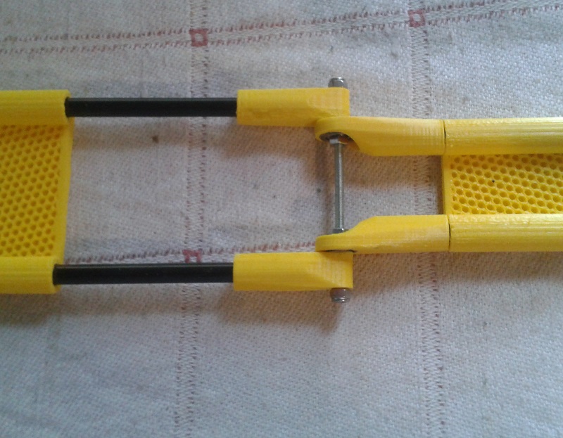
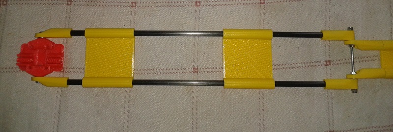
I've been busy with my carbon rod version, too. But the rods I'm planning to use are still on their way, so I only made a mockup version based on a carrier I had left over from an older Delta printer and a set of 4x300mm long 6x4 carbon rods. ( The final version will be ~4x155mm long )
The carriers have a hole pattern of 20x20mm, so I'm planning to rotate them 90° on the MGN12 linear rails. I'll use the aluminum carriers from robotdigg, although I have to borrow them from my Kossel XL delta , until the proof of concept has been made.
Now the rods have distance of 40mm to each other and the brackets ( I have to glue them to the rods ) will provide enough stiffness, I hope.
The F628zz bearings are for M3 only but have a flange, so they clamp down by tightening the screw.
|
Re: Tripteron Implementation January 01, 2017 07:18AM |
Registered: 8 years ago Posts: 5,232 |
Apsu, you like challenges?
How about building a dual X-axis printer? Make a cube from 2020 extrusions and use two carriers on the X- and Y-rail with separate Z-carriers on the opposite verticals.
Imagine how the effectors would dance with each other, simultaneously printing with two filaments
Forget it, just tried to visualize the route for separate belts for two carriers on the same rail... this would become ugly
Edited 1 time(s). Last edit at 01/01/2017 07:22AM by o_lampe.
|
Re: Tripteron Implementation January 01, 2017 11:41AM |
Registered: 7 years ago Posts: 143 |
Quote
o_lampe
I've been busy with my carbon rod version, too. But the rods I'm planning to use are still on their way, so I only made a mockup version based on a carrier I had left over from an older Delta printer and a set of 4x300mm long 6x4 carbon rods. ( The final version will be ~4x155mm long )
The carriers have a hole pattern of 20x20mm, so I'm planning to rotate them 90° on the MGN12 linear rails. I'll use the aluminum carriers from robotdigg, although I have to borrow them from my Kossel XL delta , until the proof of concept has been made.
Now the rods have distance of 40mm to each other and the brackets ( I have to glue them to the rods ) will provide enough stiffness, I hope.
The F628zz bearings are for M3 only but have a flange, so they clamp down by tightening the screw.
Hah, cool. I literally drew that exact design the other day on the whiteboard I use for hashing out rough ideas. I wasn't sure about CF rods but the rest of it seemed like a reasonable approach. Looking forward to seeing how yours behaves!
Maybe I'll grab some tubes or rods and try building it too.
|
Re: Tripteron Implementation January 02, 2017 01:56AM |
Registered: 8 years ago Posts: 9 |
I've been using a lot of concepts from Tripteron/Delteron's development in my own design experiments. I'll probably end up with something that doesn't need the revolute joints, but my opinion is that a different geometry for the tripteron's Z-axis arm could make it a lot more rigid. The issue is that the effector's weight is cantilevered on just one (Z) arm, so the base joint has to carry that entire moment (the weight of the effector x the distance from the Z-axis rail to the effector. kind of like a torque). This can be optimized for by making the Z-arm's first joint wider. (The second joint in the arm's elbow only sees half the moment). Something like a Y-arm to separate the joint into two colinear bearings would help to distribute the moment into two radial loads. The upper one gets pulled forward and the lower one gets pressed back away from the effector. Tension and compression at the base of a classic cantilever beam. An even better example of what I have in mind (though it probably wasn't set up that way for the same reason) is spacex's strongback. Just turn the picture 90 degrees.
I've got another one. Put two carriages on one extra-long rail, with independent belts, and connect them to an effector with a single linkage each. Moving them both in the same direction is your x-axis, and moving them closer together is your +y direction. This video is probably a better start to visualizing it: https://youtu.be/_vp1ELEtDN4
Up to 0:16 are the 2 degrees of freedom you need. The effector's rotation needs to be constrained by a third arm, parallel with one of the first two. (Maybe it could do double duty as the cable guide.)
Unlike tripteron, the joints' radial backlash matters, but the bearings in previous designs are already up for that task. The cantilever problem is still there, but helped somewhat by having two arms and losing the elbows. I'd still use a double-joint like I described above.
Anyway, the result would be a single rail for an XY-gantry with a usable area about 1/3 of its total length, squared. So a 300x300 build area would require a 1000mm rail. Kinematics for the y-axis are similar to a delta robot's arms. the near-half of the build area has less y-resolution, the far half has more.
Calibration could be done automatically by having both carriages pass through the same point like a non-contacting endstop to measure the distance between them. As long as the two main arms are identical lengths
As for the Z-axis, with the entire XY-gantry on one rail it might be easier to set the whole thing on leadscrews and enjoy a completely stationary bed. Essentially, take a prusa i3 and replace its y axis with a second x-carriage that uses delta kinematics. (Sorry to steal your prusa/delta lovechild metaphor, Apsu, but this is way more direct).
Unfortunately the arms passing through the build area's perimeter make it difficult to enclose without boxing up the whole thing (3x the volume). For that reason I'm currently looking into other options for a cantilevered xy gantry to retain the stationary build platform, but here's what I had planned so far using openbuilds parts. $20 for the rail, $42 for wheels, and $24 for carriage plates:
Happy 2017!
Edited 3 time(s). Last edit at 01/02/2017 02:05AM by brazenrain.
Quote
o_lampe
Apsu, you like challenges?
How about building a dual X-axis printer? Make a cube from 2020 extrusions and use two carriers on the X- and Y-rail with separate Z-carriers on the opposite verticals.
Imagine how the effectors would dance with each other, simultaneously printing with two filaments
Forget it, just tried to visualize the route for separate belts for two carriers on the same rail... this would become ugly
I've got another one. Put two carriages on one extra-long rail, with independent belts, and connect them to an effector with a single linkage each. Moving them both in the same direction is your x-axis, and moving them closer together is your +y direction. This video is probably a better start to visualizing it: https://youtu.be/_vp1ELEtDN4
Up to 0:16 are the 2 degrees of freedom you need. The effector's rotation needs to be constrained by a third arm, parallel with one of the first two. (Maybe it could do double duty as the cable guide.)
Unlike tripteron, the joints' radial backlash matters, but the bearings in previous designs are already up for that task. The cantilever problem is still there, but helped somewhat by having two arms and losing the elbows. I'd still use a double-joint like I described above.
Anyway, the result would be a single rail for an XY-gantry with a usable area about 1/3 of its total length, squared. So a 300x300 build area would require a 1000mm rail. Kinematics for the y-axis are similar to a delta robot's arms. the near-half of the build area has less y-resolution, the far half has more.
Calibration could be done automatically by having both carriages pass through the same point like a non-contacting endstop to measure the distance between them. As long as the two main arms are identical lengths
As for the Z-axis, with the entire XY-gantry on one rail it might be easier to set the whole thing on leadscrews and enjoy a completely stationary bed. Essentially, take a prusa i3 and replace its y axis with a second x-carriage that uses delta kinematics. (Sorry to steal your prusa/delta lovechild metaphor, Apsu, but this is way more direct).
Unfortunately the arms passing through the build area's perimeter make it difficult to enclose without boxing up the whole thing (3x the volume). For that reason I'm currently looking into other options for a cantilevered xy gantry to retain the stationary build platform, but here's what I had planned so far using openbuilds parts. $20 for the rail, $42 for wheels, and $24 for carriage plates:
Happy 2017!
Edited 3 time(s). Last edit at 01/02/2017 02:05AM by brazenrain.
|
Re: Tripteron Implementation January 02, 2017 04:14AM |
Registered: 7 years ago Posts: 143 |
Quote
brazenrain
I've been using a lot of concepts from Tripteron/Delteron's development in my own design experiments. I'll probably end up with something that doesn't need the revolute joints, but my opinion is that a different geometry for the tripteron's Z-axis arm could make it a lot more rigid. The issue is that the effector's weight is cantilevered on just one (Z) arm, so the base joint has to carry that entire moment (the weight of the effector x the distance from the Z-axis rail to the effector. kind of like a torque). This can be optimized for by making the Z-arm's first joint wider. (The second joint in the arm's elbow only sees half the moment). Something like a Y-arm to separate the joint into two colinear bearings would help to distribute the moment into two radial loads. The upper one gets pulled forward and the lower one gets pressed back away from the effector. Tension and compression at the base of a classic cantilever beam. An even better example of what I have in mind (though it probably wasn't set up that way for the same reason) is spacex's strongback. Just turn the picture 90 degrees.
Wow, lots of feedback in here
I absolutely agree that the Z load is imbalanced due to gravity acting against its revolute joints unlike X and Y. I've thought about different geometries, bracing, and even suspending X and Y from above to distribute some of their rigidity differently. I'm not sure yet that a lot of work there is necessary until I test some machined parts to see how Z behaves under the weight of the assembly if all the joints are much stronger materials, but your y-arm suggestion is indeed correct. All else being equal, splitting the load across a wider area will of course only help.
That said, the Delteron helpfully sidesteps pretty much all of those issues. The symmetry and arm angling causes most of the gravity load to be redirected into lateral loads on the arm joints, leaving the effector untouched. Honestly, since the same arms can be used on the Tripteron as the Delteron, if I can get a more rigid construction right away I'm going to feel hard-pressed not to try it on the Delteron first. I find it a more appealing, more elegant, and simpler design.
Quote
I've got another one. Put two carriages on one extra-long rail, with independent belts, and connect them to an effector with a single linkage each. Moving them both in the same direction is your x-axis, and moving them closer together is your +y direction. This video is probably a better start to visualizing it: https://youtu.be/_vp1ELEtDN4
Up to 0:16 are the 2 degrees of freedom you need. The effector's rotation needs to be constrained by a third arm, parallel with one of the first two. (Maybe it could do double duty as the cable guide.)
Unlike tripteron, the joints' radial backlash matters, but the bearings in previous designs are already up for that task. The cantilever problem is still there, but helped somewhat by having two arms and losing the elbows. I'd still use a double-joint like I described above.
Anyway, the result would be a single rail for an XY-gantry with a usable area about 1/3 of its total length, squared. So a 300x300 build area would require a 1000mm rail. Kinematics for the y-axis are similar to a delta robot's arms. the near-half of the build area has less y-resolution, the far half has more.
Calibration could be done automatically by having both carriages pass through the same point like a non-contacting endstop to measure the distance between them. As long as the two main arms are identical lengths
As for the Z-axis, with the entire XY-gantry on one rail it might be easier to set the whole thing on leadscrews and enjoy a completely stationary bed. Essentially, take a prusa i3 and replace its y axis with a second x-carriage that uses delta kinematics. (Sorry to steal your prusa/delta lovechild metaphor, Apsu, but this is way more direct).
Unfortunately the arms passing through the build area's perimeter make it difficult to enclose without boxing up the whole thing (3x the volume). For that reason I'm currently looking into other options for a cantilevered xy gantry to retain the stationary build platform, but here's what I had planned so far using openbuilds parts. $20 for the rail, $42 for wheels, and $24 for carriage plates:
Happy 2017!
I too had seen that design. It's from the same university that made the Tripteron. Very cool idea, though, as you said, frame:build volume ratio is fairly poor for this application. Have you seen Nicholas Sewards Hexapteron design? It also uses dual carriages on a single axis to essentially add 3 more DOF to a Tripteron-esque configuration. Maybe you'd find some inspiration in mixing in elements of his approach for the dual-carriage cantilever actuation you're envisioning.
All this detailed feedback and doing your own design work is fantastic though. I haven't gotten a lot of it along the way, so by all means, feel free. Happy 2017 to you as well!
|
Re: Tripteron Implementation January 02, 2017 05:09AM |
Registered: 8 years ago Posts: 5,232 |
|
Re: Tripteron Implementation January 02, 2017 11:24PM |
Registered: 8 years ago Posts: 9 |
I have seen the hexapteron- it's a very similar concept to the rest of that video I posted- Control two points and you can drive a rotational DoF. I think for now my design is moving towards reducing the number of sequential components between the drive system and the effector. It's how I arrived at the single-rail xy gantry, but I think I can go one step further by borrowing a concept from h-bot/corexy. I'll make my own thread one day when I build something that prints.
I actually don't think delteron's load paths are all that different from tripteron. I thought it did at first, but then I realized there still isn't any dependence on the joints for radial load. While reading the original paper on the tripteron concept, it occurred to me that the axes can be almost arbitrary and still direct the effector in 3 dimensions. Out of the 6 possible degrees of freedom each, arm only controls translation in the direction of its carriage and 2 rotational degrees (which mainly stabilizes the effector. It might be counterintuitive. Basically, holding one carriage in place - let's say Y, constrains the effector to a plane orthogonal to the carriage's axis, leaving the effector is free to move anywhere in the ZX plane within the arm's reach. Delteron's effector is especially rigid because it opposes gravity with most of the strong direction of each arm (cos of 25deg = 90%) while in tripteron the weight is unconstrained by X and Y leaving you with 100% of only the Z-arm.
Basic stuff so far that you probably already knew, but it becomes interesting when you realize that the planes can have any orientation at all as long as two of them aren't parallel. Try this on delteron - lock two axes in place and free or disconnect the third one. The effector should be able to move along a straight line, because the intersection of two planes is a line. And the intersection of that line with any other plane - that isn't a linear combination of the first two planes - is a point. The tripteron paper has a handful of example configurations, but there's an infinity of possibilities. Say I took delteron's carriages and put two of them on the same linear rail like on my concept. The arms have a 25 degree angle, so I oppose them from each other to form a 50-degree isosceles triangle. Then just connect them to an effector and add a Z-axis arm and we have another working configuration, albeit with a triangular build area and the same single-arm cantilever as the original tripteron. But now rotate that onto its side and we have a tower with two Z-arms supporting load. Or similarly, rotate the original tripteron so its diagonal points downwards as the base of a 3-sided pyramid and we have orthogonality with all 3 rails supporting load, but with a conical build volume. Delteron is unique in that its axes are parallel which makes it compact, scalable, and symmetric, but its arms aren't functionally different. Just food for thought.
Edited 1 time(s). Last edit at 01/02/2017 11:26PM by brazenrain.
Quote
Apsu
That said, the Delteron helpfully sidesteps pretty much all of those issues. The symmetry and arm angling causes most of the gravity load to be redirected into lateral loads on the arm joints, leaving the effector untouched. Honestly, since the same arms can be used on the Tripteron as the Delteron, if I can get a more rigid construction right away I'm going to feel hard-pressed not to try it on the Delteron first. I find it a more appealing, more elegant, and simpler design.
I actually don't think delteron's load paths are all that different from tripteron. I thought it did at first, but then I realized there still isn't any dependence on the joints for radial load. While reading the original paper on the tripteron concept, it occurred to me that the axes can be almost arbitrary and still direct the effector in 3 dimensions. Out of the 6 possible degrees of freedom each, arm only controls translation in the direction of its carriage and 2 rotational degrees (which mainly stabilizes the effector. It might be counterintuitive. Basically, holding one carriage in place - let's say Y, constrains the effector to a plane orthogonal to the carriage's axis, leaving the effector is free to move anywhere in the ZX plane within the arm's reach. Delteron's effector is especially rigid because it opposes gravity with most of the strong direction of each arm (cos of 25deg = 90%) while in tripteron the weight is unconstrained by X and Y leaving you with 100% of only the Z-arm.
Basic stuff so far that you probably already knew, but it becomes interesting when you realize that the planes can have any orientation at all as long as two of them aren't parallel. Try this on delteron - lock two axes in place and free or disconnect the third one. The effector should be able to move along a straight line, because the intersection of two planes is a line. And the intersection of that line with any other plane - that isn't a linear combination of the first two planes - is a point. The tripteron paper has a handful of example configurations, but there's an infinity of possibilities. Say I took delteron's carriages and put two of them on the same linear rail like on my concept. The arms have a 25 degree angle, so I oppose them from each other to form a 50-degree isosceles triangle. Then just connect them to an effector and add a Z-axis arm and we have another working configuration, albeit with a triangular build area and the same single-arm cantilever as the original tripteron. But now rotate that onto its side and we have a tower with two Z-arms supporting load. Or similarly, rotate the original tripteron so its diagonal points downwards as the base of a 3-sided pyramid and we have orthogonality with all 3 rails supporting load, but with a conical build volume. Delteron is unique in that its axes are parallel which makes it compact, scalable, and symmetric, but its arms aren't functionally different. Just food for thought.
Edited 1 time(s). Last edit at 01/02/2017 11:26PM by brazenrain.
|
Re: Tripteron Implementation January 02, 2017 11:53PM |
Registered: 7 years ago Posts: 143 |
Quote
brazenrain
...
Well, I was going to quote and respond to your post, but really you're right and I agree with everything you said
The extreme hackability/flexibility is what got me excited about building a Tripteron in the first place. It's a wide-open space just waiting for more people to get involved trying to build 'em. Seems like there was a lot of static friction and my hope was if I made one it might get the whole thing moving finally. Glad to have you part of the conversation as you definitely are seeing what I'm seeing.
The biggest challenge I find is that even very smart folks look at the idea and don't *see* it immediately. Or sometimes after another look or five. It's very counter-intuitive that you take a standard radial joint and push on it sideways, allowing you to ignore the angle/extension of the joint links, and then orthogonalize two more and you get a locatable gantry that is linear. The joint mobility is purely to allow easy extension for transferring force through the lateral rigidity. It's a weird way to transfer motion, and yet brilliantly simple.
And you're right, the colinear configuration doesn't change that aspect of it, it just introduces a combination of two angles (arm-actuator and actuator-actuator) that still result in the orthogonal force transfer. The symmetry and compactness are bonuses of that particular configuration, but indeed, the arms are identical. Force traverses the angles a little different which has pros and cons, but fundamentally it's all the same idea.
Loving this discussion
|
Re: Tripteron Implementation January 04, 2017 12:38AM |
Registered: 8 years ago Posts: 9 |
Cool, sounds like we're on the same page. The arms are purely for extension, but their shape can be misleading. I had this crazy thought experiment that you could build a more easily enclosable tripteron using drag chains as arms.
They have the exact same degrees of freedom freed, but backlash probably stacks up too easily for the X and Y axes that have to move in both directions. (maybe gravity would preload out the slop for Z?)
Anyway there's no doubt in my mind that if the root problem actually is supporting the effector's weight, then a longer joint can fix it. That's just how cantilevers work, but you'll have to be crafty about making sure the bearings are coaxial so the hinge doesn't bind. So in the spirit of simplicity and making progress faster, I wonder if this will help the current version: http://www.thingiverse.com/thing:2013647
I'd suggest printing just one to swap onto tripteron's z-axis carriage. I basically added material to brace against the printed lugs' weak direction in bending right at its weakest point, and it should improve the effector's stiffness most when the arm is extended. When the effector is closer to the z-axis rail the base joint is mainly loaded in torsion. This new geometry will help with that too but it isn't optimized for that case. If there isn't a difference at all, then the original lug thicknesses are probably sufficient. Because the new part itself is stiffer, it will require more force to clamp it down on the mating part, but I don't see it being more than you're already using. What do you think?
|
Re: Tripteron Implementation January 04, 2017 12:58AM |
Registered: 7 years ago Posts: 143 |
Quote
brazenrain
Cool, sounds like we're on the same page. The arms are purely for extension, but their shape can be misleading. I had this crazy thought experiment that you could build a more easily enclosable tripteron using drag chains as arms.
They have the exact same degrees of freedom freed, but backlash probably stacks up too easily for the X and Y axes that have to move in both directions. (maybe gravity would preload out the slop for Z?)
Yeah, I had the same thought about a variety of mechanisms. There's quite a few interesting renders and drawings and such out there of some ideas. Rhombus mechanisms, scissors, even Sarrus linkages. All the same idea essentially, radial link chains with lateral stiffness. I think the real issue is that the more joints you add, the more precise everything has to be so that, as you said, error doesn't compound worse than the 2-link simple arms. I abandoned pursuing it heavily for that reason.
Quote
Anyway there's no doubt in my mind that if the root problem actually is supporting the effector's weight, then a longer joint can fix it. That's just how cantilevers work, but you'll have to be crafty about making sure the bearings are coaxial so the hinge doesn't bind.
Agreed. But two things about that... one, the Z arm doesn't have to be the same size/length/thickness as the XY arms, and there are some possible ways to even counterweight the arm and get away with a lighter one (since we know we're always fighting the same force in the same direction).
And two, to be clear, I didn't have a *lot* of Z deflection at all. And I didn't have a properly braced Z frame section in the initial build. A full cube does help solve some of that. More in a moment...
Quote
So in the spirit of simplicity and making progress faster, I wonder if this will help the current version: http://www.thingiverse.com/thing:2013647
I'd suggest printing just one to swap onto tripteron's z-axis carriage. I basically added material to brace against the printed lugs' weak direction in bending right at its weakest point, and it should improve the effector's stiffness most when the arm is extended. When the effector is closer to the z-axis rail the base joint is mainly loaded in torsion. This new geometry will help with that too but it isn't optimized for that case. If there isn't a difference at all, then the original lug thicknesses are probably sufficient. Because the new part itself is stiffer, it will require more force to clamp it down on the mating part, but I don't see it being more than you're already using. What do you think?
I've actually tried a model with more material very recently at the weak spot, and I don't actually think that's the entire problem. I believe a couple of things are going on here with the forks.
- I chose relatively short shoulder bolts because longer than 30mm becomes oddly expensive
- Due to this and the bearing widths, in order to still have a fair amount of boss material spacing them, the forks are necessarily somewhat thin
- Being thin, they flex a little, yes, but I believe upon very careful inspection that what's also happening is the bolts are tilting in the fork holes
- Using bushings or heat-set inserts probably won't help because really the thickness of plastic at that point is likely just insufficient for this scale of frame (and thus the arm length required for a good working volume ratio)
I spent some time thinking about a pure bushing-based joint, which allow for a thinner tongue and thicker fork without necessarily enormous axles, therefore increasing the surface area of bolt/fork contact. That's Probably more the correct path to take for taking single-width two-link arms farther without significantly widening them (at which point I think a hinge-design is called for).
The other approach of course is to just increase the strength of material chosen for the forks in the current geometry. As of today, I have a machinist now working on making me a mating fork/tongue pair for my 1515 extrusions and 625 bearings. They should be ready by the weekend at latest, and possibly tomorrow/Thursday at earliest. My intention is to bolt them onto their extrusions, get the bearings, bolts, washers and such in, preload, and test deflection. I suspect they will deflect under light load orders of magnitude less than the plastic ones, and I'll greenlight him to make the other 10 brackets for me.
Then I can put the entire thing together as a cube and test the overall rigidity (please don't let there be bounce still, please) as well as how Z handles the overall weight. I suspect the assembly to clock in around 350-400g still, which is actually a lot lighter than the 2020 version with 608 bearings.
I also intend to assemble the Delteron frame and test it again with the new arms.
If I can verify that, in fact, we can get close to nailing ideal behavior with strong enough materials, I think that lets us work backwards a little bit in order to attempt to replicate it with printed part design a little better. Right now it's difficult to observe or measure what's deflecting and how much clearly enough to know for sure, but as I said, it appears to me that it's a combination of the forks bending at their bases a little (so larger radius helps) and the bolts tilting in the fork holes (so thicker forks/longer bolts help), which might dictate whether bearings can fit into the equation or not.
|
Re: Tripteron Implementation January 04, 2017 10:24PM |
Registered: 8 years ago Posts: 9 |
Ah you've been busy. Have you tested tripteron with the at least half-cube in the thingiverse model?
The problem with only using bushings is they need to slide past each other at some point which limits how much you can preload the joint. Maybe ptfe washers as a substitute for bearings.
If machined parts solve everything - a stable tripteron and non-binding delteron - that's going to be a genuinely fun task to make comparable printed parts. Aluminum is at least 20X as stiff as PLA, but there are plenty of ways to optimize the geometry to compensate. For instance, making the forks thicker will actually reduce deflection caused by bending more effectively than making the forks' radii bigger, for the same mass increase. Perpendicular flanges even more so. I'll be looking forward to the machined version working, fingers crossed.
In the meantime, if you can do it with your cad program can you post a section cut of the joint? Something like this.
|
Re: Tripteron Implementation January 04, 2017 10:43PM |
Registered: 7 years ago Posts: 143 |
Quote
brazenrain
Ah you've been busy. Have you tested tripteron with the at least half-cube in the thingiverse model?
Almost. I didn't get the side frame on it, just the back one. You can see it here pretty clearly.
Yeah, I was thinking in the same direction. Also to see how well oillite-type bushings slide against each other.Quote
The problem with only using bushings is they need to slide past each other at some point which limits how much you can preload the joint. Maybe ptfe washers as a substitute for bearings.
Quote
If machined parts solve everything - a stable tripteron and non-binding delteron - that's going to be a genuinely fun task to make comparable printed parts. Aluminum is at least 20X as stiff as PLA, but there are plenty of ways to optimize the geometry to compensate. For instance, making the forks thicker will actually reduce deflection caused by bending more effectively than making the forks' radii bigger, for the same mass increase. Perpendicular flanges even more so. I'll be looking forward to the machined version working, fingers crossed.
For sure! Super excited to see what happens.
Quote
In the meantime, if you can do it with your cad program can you post a section cut of the joint? Something like this.
Yep. I've got this and here's some other views


|
Re: Tripteron Implementation January 04, 2017 10:47PM |
Registered: 7 years ago Posts: 143 |
Quote
Apsu
Almost. I didn't get the side frame on it, just the back one. You can see it here pretty clearly.
I should clarify that I *did* build a full cube frame and put the arms on it and the "bounce" was still present, both the 2020 arms and the 1515 ones. That's what I was referencing in my post a week ago or so about how frame rigidity wasn't the main challenge.
|
Re: Tripteron Implementation January 05, 2017 12:49PM |
Registered: 8 years ago Posts: 5,232 |
I just stumbled across an interesting bearing type called "cam follower cf5"
This might be a good solution for the z-axis dual rods?
This might be a good solution for the z-axis dual rods?


Sorry, only registered users may post in this forum.