More Motor Problems
Posted by Anthrochick
|
More Motor Problems September 05, 2012 02:54PM |
Registered: 11 years ago Posts: 45 |
So, after buying all new motors, double checking all the connections on my sanguinololu board, and rewiring everything, I am still unable to get my motors to budge. At one point, and only on this one occasion, one motor started to vibrate but wouldn't turn and as soon as I turned the trimpot up a bit, it stopped. This has been the only indication of life I have gotten. I turned the trimpots for all the motors back to see if perhaps I was letting too much power through. Nothing. I turned them all up just in case they weren't getting enough power. Nothing. I checked my power supply, everything seems fine. The only other problem right now is that the hot end won't heat up but I'm pretty certain it is due to the fact that the whole thing has been holding on by a thread since I bought it. I've double checked the wiring and checked my motor wiring against the wiring of the seller's and according to the seller, it should be working. What have I missed?
If it matters (perhaps there was a bad batch, or something?) I bought my stepstick drivers from botronicz.
Bringing 3D printing to America's classrooms.
Follow my efforts at TheChicksNest.blogspot.com
If it matters (perhaps there was a bad batch, or something?) I bought my stepstick drivers from botronicz.
Bringing 3D printing to America's classrooms.
Follow my efforts at TheChicksNest.blogspot.com
|
Re: More Motor Problems September 06, 2012 11:56AM |
Registered: 12 years ago Posts: 939 |
The fact that the Hotend doesn't heat either means it's most likely a problem with the 12V supply.
Most of the board will run on 5V but the steppers won't move and the hot end won't heat.
Does your thermistor show something reasonable for the hot end temperature?
Put a volt meter on the Hotend connector first, it's easier to trace back, when you set it to heat in the firmware, what voltage do you see?
|
Re: More Motor Problems September 06, 2012 04:49PM |
Registered: 11 years ago Posts: 45 |
The problem is that I recieved my hot end with a broken (quite literally as it is in two pieces) thermistor so I am just going by touch until my new thermistors arrive. I'm using a 16V- 32V supply from an HP printer and I've tried both the 16V side and the 32V side without any luck. I'm reluctant to take apart my PC PSU since I may need it again for use with my old PC. I also should say that i took the voltage regulator off of my board since it was heating up way too hot and caused some sparking when I had it connected initially. This, however, was long before I had even connected my new motors. I'm just wondering what it was that had the one motor juddering away when I plugged itin straight out of the box.
Bringing 3D printing to America's classrooms.
Follow my efforts at TheChicksNest.blogspot.com
Bringing 3D printing to America's classrooms.
Follow my efforts at TheChicksNest.blogspot.com
|
Re: More Motor Problems September 06, 2012 06:05PM |
Registered: 12 years ago Posts: 939 |
Most firmwares go into a safe state if they don't get a valid thermistor reading and won't let you do anything including move axis.
You can work around this by setting the hot end thermistor in the firmware to not used, I think it's 0 in marlin, but it might be -1.
The next most common error is endstop settings, again easy way to test if you have an issue there is to disable them temporarily.
I'm not familiar with the Sanguinolu board so I can't help debug any possible damage there.
Edited 1 time(s). Last edit at 09/06/2012 06:07PM by Polygonhell.
|
Re: More Motor Problems September 07, 2012 07:32AM |
Registered: 13 years ago Posts: 7,616 |
The motor current trimpot can be pretty close to zero (full counterclockwise) and a motor without mechanical load would still make turns. Putting it too high up just makes the thermal protection kick in.
In case you didn't yet: remove the belts to be sure there is no mechanical blocking. Also measure the Pololu pins, Vmot should 12V, ENABLE should be < 1V, etc.. Third, don't trust wire colors. Actually test where the two pairs of wires are.
In case you didn't yet: remove the belts to be sure there is no mechanical blocking. Also measure the Pololu pins, Vmot should 12V, ENABLE should be < 1V, etc.. Third, don't trust wire colors. Actually test where the two pairs of wires are.
| Generation 7 Electronics | Teacup Firmware | RepRap DIY |
|
Re: More Motor Problems September 07, 2012 02:12PM |
Registered: 11 years ago Posts: 45 |
With the trimpot, I can turn and turn and turn without any kind of resistance in any direction. I dont remember being able to turn a trimpot that much but perhaps my memory is faulty since it's been well over 10 years (high school)since I last fiddled with one. The first thing I did was check the belts just to make sure there was nothing blocking any sort if movement but there doesn't seem to be.
I'm not very familiar with the firmware and using arduino since my cs background is pretty much limited to python, matlab,c, java and html so I'm not sure how I would edit anything there. i had assumed there would be some kind of shut off if there was too much or too little power flowing as well as if there was a damaged component (thermistor) but again, I'm not sure the procedure to get around that.
Bringing 3D printing to America's classrooms.
Follow my efforts at TheChicksNest.blogspot.com
|
Re: More Motor Problems September 07, 2012 05:58PM |
Registered: 12 years ago Posts: 939 |
You may have broken the pot, or it may have shipped broken, total travel is less than 1 revolution and they have stops at either end, but it doesn't require a lot of force to break them.
What temperature is proterface reading from the thermister and what output are you seeing from the firmware in proterface.
Unless you are enormously lucky and the board shipped with a correctly configured firmware, you're going to be learning to change it.
What temperature is proterface reading from the thermister and what output are you seeing from the firmware in proterface.
Unless you are enormously lucky and the board shipped with a correctly configured firmware, you're going to be learning to change it.
|
Re: More Motor Problems September 08, 2012 05:10PM |
Registered: 11 years ago Posts: 477 |
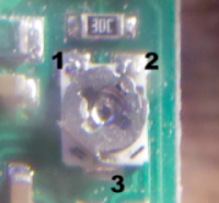
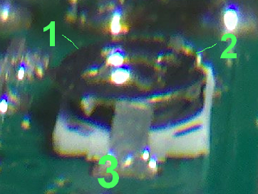
I think I figured out why it/they're spinning freely. On the older boards that employ the open frame trimpot, there's a tiny little metal tab that sticks up on the side with a single SMT tab and acts as the stop. If that gets bumped away from the trimpot, it can rotate freely over a full 360 degrees...and beyond!
Anyway...if you look at it with a magnifying glass you can probably see what I did. Carefully pushing it back into position with a jeweler's screwdriver, (while the trimpot is rotated back away from the stop position) re-engages the stop. I can't say if the trimpot is permanently compromised by excessive rotation yet... I'll post when I'm done modding my MK1 board and have time to test the trimpot on the dead board I got for layout purposes)
(see pin marked 3 in 1st attached photo, then view the second photo for exactly what I mean)
|
Re: More Motor Problems September 10, 2012 01:17PM |
Registered: 11 years ago Posts: 45 |
I just heard back from Botronicz and it is what xiando said. The boards I recieved are older ones that lack the trimpot endstops. However, this still doesn't account for the motor issues I've been having. I have just recieved my new thermistors as well so I'll be trying that in a couple of minutes to see if I can get any sort of temp reading.
Bringing 3D printing to America's classrooms.
Follow my efforts at TheChicksNest.blogspot.com
Bringing 3D printing to America's classrooms.
Follow my efforts at TheChicksNest.blogspot.com
|
Re: More Motor Problems September 10, 2012 05:03PM |
Registered: 11 years ago Posts: 477 |
Anthrochick,
I'm not sure what kind of "lab" tools you have at your disposal, so I'm waffling on how to advise you wrt troubleshooting. (and forgive me if you've already done this stuff...)
But if it were me, I'd be inclined to do the following to at least ensure that my drivers and motors were working as expected:
Notes:
a) I assume the motors have been removed from the unit or the wiring has been thoroughly inspected and verified to not contain shorts or open circuits if they are left in situ)
b) do not presume to power the VDD side with 12V. Only the motor side, and the other should have 5V, not 3.3V (IMO)
c) If you can get one and get it set for use, a function generator capable of delivering an isolated, 5V, 10Hz-200Hz square wave would be very very useful for driving the step pin (not ~required, but...)
EDIT: d) This is not a complete test. It is enough to verify that the motor driver pair either works or doesn't. (see my last comment) for the sake of brevity, fix the problem with the "stop", then carefully adjust so that the pot is set roughly half way between. can't offer much more than that right now
1) Plug one of your pololu driver "chip"s (ie, the pinned 4983/88 board) to a breadboard, then wire it up for manual operation with 5V (digital side) and 12V (VMOT) supplies, using the higher-level schematic as a reference (I snuck it in below). (Make sure the power supplies are turned off during the wiring of the circuit and motors)
If you have one available, use a nice fat electrolytic cap to filter the 12V supply as close to the 4983/88 as possible on the breadboard, and make sure that the side with the (-) on it is connected to the GND pin next to VMOT. if it gets turned around you end up with a smoky capacitor. Sometimes it happens to the best of us.
For the purposes of this test, we don't care which direction it's set for, or if the stepping is 1/16th or full on, so let's go ahead and connect ENABLE, MS1, MS2, MS3, and DIR to the 5V COM,
2) connect a push button switch (ideally) or a toggle switch between 5V and the step input, with a small cap (~0.1uF) across the switch as a crude debounce (keeps the switch closure from throwing multiple steps while the switch is closing)
3) jumper SLEEP and RESET together, then connect one or the other to the VDD pin using a 100K resistor.
Now we're ready to connect a motor for testing. But wait!
Let's go back and make darn sure the wires are "right".
Get your trusty volt/ohm meter and verify that the wires actually make sense. If they're not, well, needless to say, the motor ain't gunna run.
I believe you've already seen this part, but let's assume you haven't for the sake of ...well for the sake of whatever, let's do it again...
If I recall correctly, you have six wire motors, correct?
If not, just make sure the wire pairs aren't open circuits. (the two phases are electrically isolated from each other, so wires for pair 1A/1B will show very high resistance from those of 2A/2B ) and skip the next set of tests. When you've determined that you have isolated the two pairs, tape them apart from each other. Label one pair "possibly 1" and the other "possibly 2"
----next set of tests----
Ok, so now for six wire motors:
Just like the 4-wire motors, the two functional phases are isolated, so first find out which triplets have connections with each other and which don't by finding out which have non-~infinite resistance between them, then tape the triplets apart from each other so we don't get confused later on.
Now, let's call a single triplet's wires, 1, 2 and 3. Measure the resistance between pairs 1 & 2, 1& 3, and 2 & 3.
the pair that shows the highest resistance are the wires we want. tape the end of the other wire to keep it electrically inactive. (so it can't accidentally short to the frame or something else later on. And if you have some, use heat shrink wrap to do the job throughly. In fact, snip any bare (stripped) wire off that one first, then tape it off or shrinkwrap it, just to further the goal of eliminating it from future confusion.
do the same for the other triplet.
Now we have the four wires we need isolated out. As was suggested above for the four wire motor, Label one pair "possibly 1" and the other "possibly 2"
-------end of next set of tests-------
Do the wire colors match with what the seller said? If so, go ahead and wire them to the breadboarded 4983/88 as he/she suggested. (noting what I say in the next sentence
If not, we have to guess (and indeed we may still have to). Write down the colors of pair 1 and pair 2 and call them something, like possibly1-A, possibly-1B, possibly2-A[/b], possibly-2B
Now we try them. we should get rotation from one of the sets of connections below (I thnik I covered them all anyway)
motor..............4983/88
possibly-1A >> 1A
possbily-1B >> 1B
possibly-2A >> 2A
possibly-2B >> 2B
OR
possibly-1B >> 1A
possbily-1A >> 1B
possibly-2A >> 2A
possibly-2B >> 2B
OR
possibly-1A >> 1A
possbily-1B >> 1B
possibly-2B >> 2A
possibly-2A >> 2B
OR
possibly-1B >> 1A
possbily-1A >> 1B
possibly-2B >> 2A
possibly-2A >> 2B
So now we just give things a quick final lookover to make sure there are no obvious shorts or wires that have come loose, and we can power up the two supplies and test the motor.
At this point, pushing the push button (or toggling it back and forth) *Should make the motor rotate. Clever says taping a bit of paper to the end of the shaft with some sort of marker on it will allow you to easily observe the direction of motion.
And if you can get your hands on one and set it for a 5V square wave out, a function generator would come in very handy just about now, to relieve you of toggling the switch. (in fact, that would be a very nice thing to use so you could also set the current limit) fwiw, you'd keep the swithc, jsut instead of hooking it to the 5V supply, you'd use the square wave out as the source. Sorry, no pics for that...
I'd blather on in more detail but I have to get back to work.
Edited 2 time(s). Last edit at 09/10/2012 05:08PM by xiando.
I'm not sure what kind of "lab" tools you have at your disposal, so I'm waffling on how to advise you wrt troubleshooting. (and forgive me if you've already done this stuff...)
But if it were me, I'd be inclined to do the following to at least ensure that my drivers and motors were working as expected:
Notes:
a) I assume the motors have been removed from the unit or the wiring has been thoroughly inspected and verified to not contain shorts or open circuits if they are left in situ)
b) do not presume to power the VDD side with 12V. Only the motor side, and the other should have 5V, not 3.3V (IMO)
c) If you can get one and get it set for use, a function generator capable of delivering an isolated, 5V, 10Hz-200Hz square wave would be very very useful for driving the step pin (not ~required, but...)
EDIT: d) This is not a complete test. It is enough to verify that the motor driver pair either works or doesn't. (see my last comment) for the sake of brevity, fix the problem with the "stop", then carefully adjust so that the pot is set roughly half way between. can't offer much more than that right now
1) Plug one of your pololu driver "chip"s (ie, the pinned 4983/88 board) to a breadboard, then wire it up for manual operation with 5V (digital side) and 12V (VMOT) supplies, using the higher-level schematic as a reference (I snuck it in below). (Make sure the power supplies are turned off during the wiring of the circuit and motors)

If you have one available, use a nice fat electrolytic cap to filter the 12V supply as close to the 4983/88 as possible on the breadboard, and make sure that the side with the (-) on it is connected to the GND pin next to VMOT. if it gets turned around you end up with a smoky capacitor. Sometimes it happens to the best of us.
For the purposes of this test, we don't care which direction it's set for, or if the stepping is 1/16th or full on, so let's go ahead and connect ENABLE, MS1, MS2, MS3, and DIR to the 5V COM,
2) connect a push button switch (ideally) or a toggle switch between 5V and the step input, with a small cap (~0.1uF) across the switch as a crude debounce (keeps the switch closure from throwing multiple steps while the switch is closing)
3) jumper SLEEP and RESET together, then connect one or the other to the VDD pin using a 100K resistor.
Now we're ready to connect a motor for testing. But wait!
Let's go back and make darn sure the wires are "right".
Get your trusty volt/ohm meter and verify that the wires actually make sense. If they're not, well, needless to say, the motor ain't gunna run.
I believe you've already seen this part, but let's assume you haven't for the sake of ...well for the sake of whatever, let's do it again...
If I recall correctly, you have six wire motors, correct?
If not, just make sure the wire pairs aren't open circuits. (the two phases are electrically isolated from each other, so wires for pair 1A/1B will show very high resistance from those of 2A/2B ) and skip the next set of tests. When you've determined that you have isolated the two pairs, tape them apart from each other. Label one pair "possibly 1" and the other "possibly 2"
----next set of tests----
Ok, so now for six wire motors:
Just like the 4-wire motors, the two functional phases are isolated, so first find out which triplets have connections with each other and which don't by finding out which have non-~infinite resistance between them, then tape the triplets apart from each other so we don't get confused later on.
Now, let's call a single triplet's wires, 1, 2 and 3. Measure the resistance between pairs 1 & 2, 1& 3, and 2 & 3.
the pair that shows the highest resistance are the wires we want. tape the end of the other wire to keep it electrically inactive. (so it can't accidentally short to the frame or something else later on. And if you have some, use heat shrink wrap to do the job throughly. In fact, snip any bare (stripped) wire off that one first, then tape it off or shrinkwrap it, just to further the goal of eliminating it from future confusion.
do the same for the other triplet.
Now we have the four wires we need isolated out. As was suggested above for the four wire motor, Label one pair "possibly 1" and the other "possibly 2"
-------end of next set of tests-------
Do the wire colors match with what the seller said? If so, go ahead and wire them to the breadboarded 4983/88 as he/she suggested. (noting what I say in the next sentence
If not, we have to guess (and indeed we may still have to). Write down the colors of pair 1 and pair 2 and call them something, like possibly1-A, possibly-1B, possibly2-A[/b], possibly-2B
Now we try them. we should get rotation from one of the sets of connections below (I thnik I covered them all anyway)
motor..............4983/88
possibly-1A >> 1A
possbily-1B >> 1B
possibly-2A >> 2A
possibly-2B >> 2B
OR
possibly-1B >> 1A
possbily-1A >> 1B
possibly-2A >> 2A
possibly-2B >> 2B
OR
possibly-1A >> 1A
possbily-1B >> 1B
possibly-2B >> 2A
possibly-2A >> 2B
OR
possibly-1B >> 1A
possbily-1A >> 1B
possibly-2B >> 2A
possibly-2A >> 2B
So now we just give things a quick final lookover to make sure there are no obvious shorts or wires that have come loose, and we can power up the two supplies and test the motor.
At this point, pushing the push button (or toggling it back and forth) *Should make the motor rotate. Clever says taping a bit of paper to the end of the shaft with some sort of marker on it will allow you to easily observe the direction of motion.
And if you can get your hands on one and set it for a 5V square wave out, a function generator would come in very handy just about now, to relieve you of toggling the switch. (in fact, that would be a very nice thing to use so you could also set the current limit) fwiw, you'd keep the swithc, jsut instead of hooking it to the 5V supply, you'd use the square wave out as the source. Sorry, no pics for that...
I'd blather on in more detail but I have to get back to work.
Edited 2 time(s). Last edit at 09/10/2012 05:08PM by xiando.
|
Re: More Motor Problems September 11, 2012 02:34PM |
Registered: 11 years ago Posts: 45 |
Thank you so much for such a detailed response, xiando! Wow! I will definitely give that a try if it still doesn't work after I upload new firmware. Also, for some reason, I was able to get some sounds out of my motors but only for a second or two. I'm not sure what that means but at least it's a sign, right?
Edited 1 time(s). Last edit at 09/11/2012 02:47PM by Anthrochick.
Bringing 3D printing to America's classrooms.
Follow my efforts at TheChicksNest.blogspot.com
Edited 1 time(s). Last edit at 09/11/2012 02:47PM by Anthrochick.
Bringing 3D printing to America's classrooms.
Follow my efforts at TheChicksNest.blogspot.com
|
Re: More Motor Problems September 11, 2012 03:20PM |
Registered: 11 years ago Posts: 477 |
yw Anthro. Tain't complete by any means, but I suspect if you need, it will help a little. Sorry you've been having so many problems. BTW, from another thread, I wonder, do you have "real" pololus or the chinese knock offs? If they're the knock offs, you may be experiencing an issue that was brought up by Idolcrasher here. It has some interesting info that might possibly benefit you, perhaps even more than my ramblings.
regards,
x
regards,
x
|
Re: More Motor Problems September 13, 2012 11:37PM |
FYI: Our boards aren't Chinese clones, they're American made StepSticks. We use genuine Allegro A4988 parts. We also use .05 ohm sense resistors, just like the Pololu's, so you can get a full 2 amps per coil from the driver. That is, of course, if you can keep the driver chip cooled down!
We have now changed our production to use the pots WITH the end stop tab. We initially felt those pots had very weak end stops, but they seem to have caused too much confusion with just turning 360 degrees without a stop. Hopefully the small end stop tab won't cause problems. I believe we use the same part as Pololu.
BTW, We are working to release a special version of the StepStick with a substantial cooling improvement to allow you to drive significantly more current.
Thank you for purchasing our StepStick's Anthrochick! Please let us know if you feel you are having a problem with our board and we are more than happy to resolve it.
|
Re: More Motor Problems September 14, 2012 01:38AM |
Registered: 11 years ago Posts: 477 |
Sorry for the misattribution. I wasn't aware outside the references made by other folks. You're right, the end stops are pretty pathetic, even on the pololu 4983 board, although they seem to have learned their lesson, as evidenced by the promo shots for the newer 4988 board.
As to the trimpots themselves, speaking as an engineer with over 20 years designing for high vibe environments, I'd suggest that you consider replacing the open frame trimpot with an encapsulated version. As you are probably aware, one of the ways we mitigate drift in high vibe environments is by applying Vibratite or similar proven solutions to trimpots to lock their position, once set, since inherent rotational "rigidity" can't be relied on in those environments due to unknown resonances and the effect upon components within their sphere of action. Open frame trimpots are not conducive to this end.
As to the trimpots themselves, speaking as an engineer with over 20 years designing for high vibe environments, I'd suggest that you consider replacing the open frame trimpot with an encapsulated version. As you are probably aware, one of the ways we mitigate drift in high vibe environments is by applying Vibratite or similar proven solutions to trimpots to lock their position, once set, since inherent rotational "rigidity" can't be relied on in those environments due to unknown resonances and the effect upon components within their sphere of action. Open frame trimpots are not conducive to this end.
Sorry, only registered users may post in this forum.