Sanguinololu: Sanguino + Pololus - Rev 0.7 
Posted by joe m
|
Sanguinololu: Sanguino + Pololus - Rev 0.7 February 11, 2011 01:19PM |
Registered: 13 years ago Posts: 16 |
Sanguinololu
Wiki page: [reprap.org] - Please check here for the latest and greatest info.
Roughly translated: I bleed, pololu.
Current revision: 0.7 Updated March 3, 2011
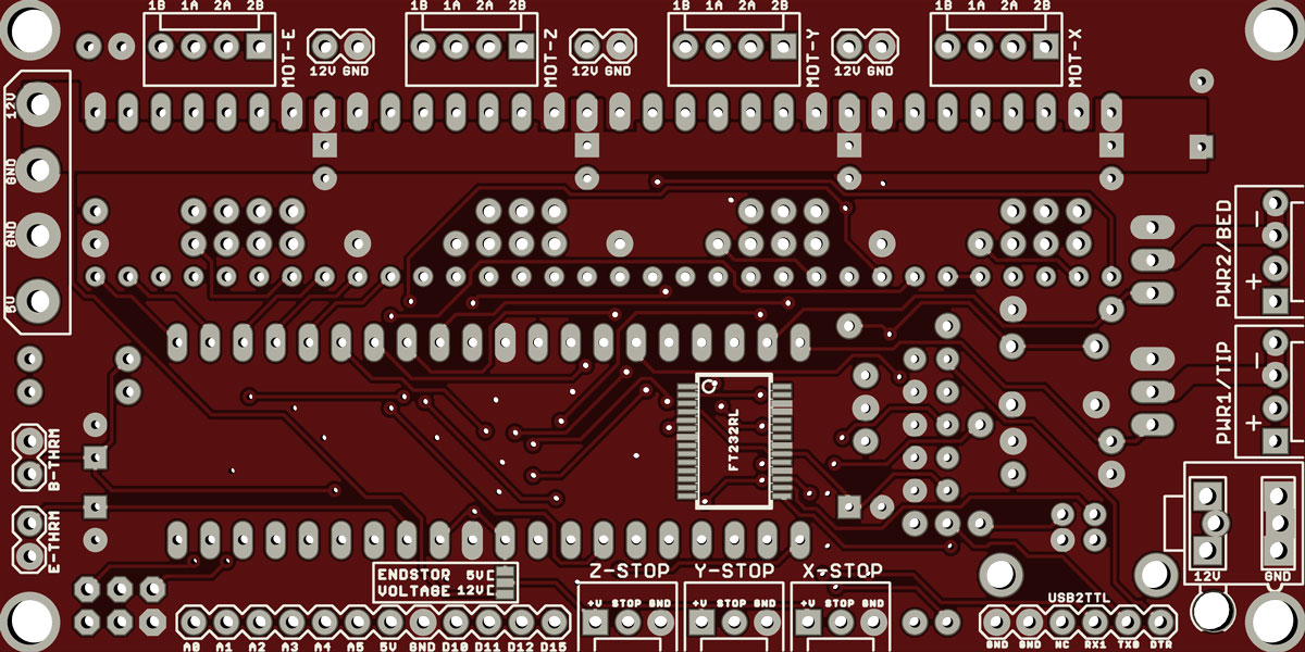
Attached to this post are board and schematic images, or go to [imgur.com]
Here is a project I've been working on. I would like a nice clean board to control my currently un-born Reprap, and due to its cost and simplicity I've chosen to use the Sanguino Arduino compatible board paired with a set of Pololu Allegro A4983 Stepper Motor Driver Carrier boards. In order to keep things tidy, I've mushed all this into one board.
Update!
The revision 0.6 PCBs have been shipped! Now for their trek across the Pacific.... In order to keep prices cheap, there will be a surplus of these boards. hit me up in #reprap if you want a sample. And to source the parts I've created a parts list on [www.mouser.com] - please note that the 0.6 revision does not have pads for the voltage regulator, and in order to be powered by USB bus, a greenwire must be soldered.
Oh, here's a pic of the 0.1 board assembled, the first prototype (they grow up so quickly...):
Two more pics at [imgur.com]
Features:
Please let me know what you think, or if you have any feature ideas, or see any mistakes, or if you're interested in contributing.
Revision history:
Rev 0.7
Added footprints for voltage regulator for those wanting to use laptop power brick, etc. The vreg component footprints are hidden under the ATX power supply for space saving and to prevent both from being in use.
Enabled USB bus power for logic side.
Connected the 5v pin on the USB2TTL header so that either a: ftdi cable can power the board, or b: The board can power a bluetooth serial module (bluesmirf).
Rev 0.6
Made changes suggested regarding putting power pin in the middle of endstop sense connector.
Shrunk board to metric specifications for boardhouse - board size now 100mm x 50mm - just a tad smaller than 4"x2"
Increased spacing between connectors to facilitate polarized or locking connector types / wire headers
Changed orientation of MS1/2/3 jumpers to (hopefully) make it easier to remove / put on, and give more room to the pololu decoup caps
Sent design to boardhouse for prototypes
Rev 0.3
MS1/2/3 for each motor separated. Unfortunately the best place for this to go is under the pololus, needing you to remove the pololu to change it's microstepping settings. Oh well, I'm hoping this is a set-it-and-forget-it type of thing.
Added optional 4-pin atx 12v connector to support large hotbed or extruder loads, up to 20A. 3A if just using the hdd connector
Adjusted schematic to put MOSFETs gates on PWM pins for less software intense temp control.
Moved endstop connectors to other side of board.
Added 12V power connectors in their place, for always on fan, or whatever. Watch out for current rating. Maybe a couple of fuses is in order....
Rev 0.1
First prototype, first design, first PCB ordered, first assembled, etc. Pics: [imgur.com]
Edited 29 time(s). Last edit at 03/04/2011 01:21AM by joe m.
Wiki page: [reprap.org] - Please check here for the latest and greatest info.
Roughly translated: I bleed, pololu.
Current revision: 0.7 Updated March 3, 2011
Attached to this post are board and schematic images, or go to [imgur.com]
Here is a project I've been working on. I would like a nice clean board to control my currently un-born Reprap, and due to its cost and simplicity I've chosen to use the Sanguino Arduino compatible board paired with a set of Pololu Allegro A4983 Stepper Motor Driver Carrier boards. In order to keep things tidy, I've mushed all this into one board.
Update!
The revision 0.6 PCBs have been shipped! Now for their trek across the Pacific.... In order to keep prices cheap, there will be a surplus of these boards. hit me up in #reprap if you want a sample. And to source the parts I've created a parts list on [www.mouser.com] - please note that the 0.6 revision does not have pads for the voltage regulator, and in order to be powered by USB bus, a greenwire must be soldered.
Oh, here's a pic of the 0.1 board assembled, the first prototype (they grow up so quickly...):

Two more pics at [imgur.com]
Features:
- *Small design - board is 100mm x 50mm (4" x 2"), 2 sided, a bunch of vias (DIY routed 1 sided design in the works)
*Sanguino clone, Atmel's ATMEGA644
*Up to 4 Pololu (or Pololu compatible) on-board (X,Y,Z,Extruder) (A4983 without voltage regulator)
*Supports multiple power configurations:
---Logic & Motors supplied by ATX power supply (needs molex harddrive connector, and optional 4pin atx connector for additional 12v)
---Motors supplied by 5mm screw terminal (7v-35v)
---Logic supplied by USB bus (if connector is installed)
---Logic supplied by optional on-board voltage regulator (molex harddrive connector cannot be installed at the same time)
*Supports multiple communication configurations:
---FT232RL on-board for USB connectivity
---USB2TTL header is available for FTDI cable, or BlueSMIRF bluetooth module
*Edge connectors for all wire connections, for vertical jumpers or right-angle tidyness, with or without polarizing tab
*Silkscreen for connectors on both sides of the board, facilitating bottom cable connections for even more tidyness
*Sanguino extra pin header for expansion (6 analog IO and 4 digital IO - two for uart2, and two PWM pins)
*All through-hole components (except FTDI chip) for easy DIY soldering
*2 thermistor connectors with circuitry
*2 N-MOSFETs for extruder/bed, or whatever
*Selectable 12v/5v endstop voltage
Please let me know what you think, or if you have any feature ideas, or see any mistakes, or if you're interested in contributing.
Revision history:
Rev 0.7
Added footprints for voltage regulator for those wanting to use laptop power brick, etc. The vreg component footprints are hidden under the ATX power supply for space saving and to prevent both from being in use.
Enabled USB bus power for logic side.
Connected the 5v pin on the USB2TTL header so that either a: ftdi cable can power the board, or b: The board can power a bluetooth serial module (bluesmirf).
Rev 0.6
Made changes suggested regarding putting power pin in the middle of endstop sense connector.
Shrunk board to metric specifications for boardhouse - board size now 100mm x 50mm - just a tad smaller than 4"x2"
Increased spacing between connectors to facilitate polarized or locking connector types / wire headers
Changed orientation of MS1/2/3 jumpers to (hopefully) make it easier to remove / put on, and give more room to the pololu decoup caps
Sent design to boardhouse for prototypes
Rev 0.3
MS1/2/3 for each motor separated. Unfortunately the best place for this to go is under the pololus, needing you to remove the pololu to change it's microstepping settings. Oh well, I'm hoping this is a set-it-and-forget-it type of thing.
Added optional 4-pin atx 12v connector to support large hotbed or extruder loads, up to 20A. 3A if just using the hdd connector
Adjusted schematic to put MOSFETs gates on PWM pins for less software intense temp control.
Moved endstop connectors to other side of board.
Added 12V power connectors in their place, for always on fan, or whatever. Watch out for current rating. Maybe a couple of fuses is in order....
Rev 0.1
First prototype, first design, first PCB ordered, first assembled, etc. Pics: [imgur.com]
Edited 29 time(s). Last edit at 03/04/2011 01:21AM by joe m.
|
Re: Sanguinololu: Sanguino + Pololu Allegro Stepper Motor Driver February 11, 2011 02:19PM |
Registered: 16 years ago Posts: 438 |
Well, I'm not an electrical guy, but you asked, and there are a couple things I noticed here.
First, your endstop connectors are right next to your motor connectors. This implies that the traces on the board pass near eachother, especially as the processor is on the other side of the board from there - that trace has to pass the pololus.
Driving a stepper is a high-current high-frequency thing, and generates a significant amount of electrical noise. It's recommended to run the motor wires as far from endstop wires as possible to prevent false readings. I think that'll give you trouble with this design, though maybe you have capacitors on them for noise suppression? That may be enough.
The thermistor connectors are at least on the other side of the board though, so that's good.
I made the suggestion elsewhere that since the pololu breakout boards are significantly more expensive than the bare chip and components, it would be cheaper to just mount those on the board. You already have enough space, after all. But then they're hard to replace if the chip gets fried. So put traces on for the chips and mount the chip, but leave a "footprint" with holes for the headers for a pololu brand daughter board. So if a chip gets fried you can unsolder and replace it, or get out a knife and cut the traces on the inside of those holes, solder headers in, and mount a daughter board. I think that'd be cool, but it would add some cost (drilling extra holes that may never be used) so I don't know how practical it'd be.
Looking at the schematic, you have one set of microstep selection jumpers for all controllers. I think most people have a different microstep setting on Z, and maybe on E, b/c they're so different from X and Y, firmware can't send step signals fast enough, noise control, whatever other reasons.
You've included just enough here to run a standard reprap with hotbed. Any expansion would have to be done through jp6 there - How many of those pins are ADC or PWM capable for adding another fan, heater, or temperature sensor? I suppose I could look that up... 6 ADC and 2 PWM. Not bad.
Any expansion would have to be done via a breadboard or something, but it looks very nice overall. I wish I could afford one, but I feel that I have to get things working with what I've got first. I have sufficient for my needs.
--
I'm building it with Baling Wire
|
Re: Sanguinololu: Sanguino + Pololu Allegro Stepper Motor Driver February 11, 2011 03:48PM |
Registered: 13 years ago Posts: 16 |
jgilmore,
Thanks for the awesome analysis!
I hadn't considered the high power switching implications on the signal wires, this will definitely have to be tested, and maybe relocated. They were put on the top of the board for placement, it seemed like a good place to put the pin connectors, as that space really isn't used for anything else.
I did make sure that all the high power lines (12v, motor wires) were short, and that the traces were wide enough to support the max current on that net. Also, the signal wires for the endstops run on the top of the board, while the power and motor connections are on the bottom... Not sure if this would help with crosstalk or not
Regarding the pololu vs bare allegro, I like the A4983 chip because it supports all modes of micro stepping. However it only comes in a QFP package - hard to solder by hand. I like the pololu implementation because it breaks it out into a dip-esque package.
The A4982 is a similar device, in tssop package, but is missing MS3 pin, limiting the number of micro step settings you can chose. Still though, I should look at this as an option.
I hadn't considered that users may want to have different step settings per axis. I agree, the MSx jumpers could be split out into each pololu.. the question is, where to put em.
Thanks for the great feedback. I'll add a page to the Wiki and put the eagle files in source control.
Edited 1 time(s). Last edit at 02/11/2011 03:51PM by joe m.
|
Re: Sanguinololu: Sanguino + Pololu Allegro Stepper Motor Driver February 11, 2011 04:04PM |
Registered: 13 years ago Posts: 26 |
woah, I was going to do this. Looks good, most of the electrical concerns were raised already so I'll just post a feature I'd like to see 
I'd like to change the footprint for the pololu drivers to accomodate both the voltage regulated and non-regulated versions. The regulated version is a bit wider and about half again as long. (I want this because the standard drivers ALWAYS sell out now) This will increase the size of the board a bit but will make it much more versatile. Maybe rotate the heater connectors 90 degrees to allow for edge connectors (IMO vertical connections look tacky on a finished bot and get in the way if you want to mount anything above it like a fan)
I may make the modifications for you once I finish my bot but I can see how they could greatly benefit your original.
Mark
|
Re: Sanguinololu: Sanguino + Pololu Allegro Stepper Motor Driver February 11, 2011 04:42PM |
Registered: 16 years ago Posts: 438 |
I don't think it's at all practical to include footprints for both with and w/o voltage regulators, due to the different widths and the much larger size of the one with the regulator. However...
One feature of the RAMPS board that I thought interesting is the use of pins sticking *up* from the pololus for the stepper motor connections. That way those traces never hit the board at all, and thus don't take up space.
The Adrian's original pololu based electronics used right angle pin connectors to mount the pololus between two pieces of strip boards.
The only connectors on the other side of *both* pololu stepper drivers is the motor, and power both 12V+gnd and 5v+gnd.
Might it be practical to mount them all sideways with the motor connector on top, and simple wires run between them? That'd keep ALL of the 12V power off the main board. Or at least the stepper motor power, anyway.
And you'd be able to use either stepper driver, as the basic pinout on the other side is the same on both. You'd have to arrange them so the longer pololu version didn't hit anything, but there's no need to hook anything up to those extra pins.
Of couse, it would be fragile with only one edge of each board supported... But it'd take up a lot less space!
Oh, and joe? How hard would it be to include the unpopulated traces for the A4983 chips, following the schematic here? I just looked at my carrier boards, and they are a double sided design, which would be inconvenient, but maybe without the sleep/reset pins broken out it wouldn't be needed. Even if you don't want to do that, others might.
Of course, by the same token it might be nice to include pads for the TQFP version of the chip, which isn't something that you care about.
--
I'm building it with Baling Wire
|
Re: Sanguinololu: Sanguino + Pololu Allegro Stepper Motor Driver February 11, 2011 07:49PM |
Registered: 13 years ago Posts: 16 |
The problem with the motor pins sticking out of the pololu is cooling... i'm always afraid that jumper or the wires will get caught on the pololu heatsink and rip it off, or restrict airflow or something.
I also found another issue: the 12v molex connector can only support around 11A (according to wikipedia). With up to 8 of those amps going to the stepper motor, there isn't capacity for a high power hotbed or extruder tip. I need to get more power onto this board, but the ATX20/24 connector is so big and bulky.
I'm considering a 4 pin ATX connector (2x 12v) as that should be easy to put on the board, and supplies quite a bit.
Another option is to send that 12v directly from the power supply to the hotbed, then just using the 4 pin molex connectors two ground wires for return - the two GND wires will support 22A, enough for 8A for motors, and 14 left for hotbed & extruder tip.
Ah, even in that case i could see issues when using a 10A hotbed and a >4A extruder tip...
Ideas?
|
Re: Sanguinololu: Sanguino + Pololu Allegro Stepper Motor Driver February 11, 2011 08:20PM |
Registered: 16 years ago Posts: 438 |
Line voltage for the heated bed has always seemed to me to be the most reasonable solution. Especially with the PC-type power supplies being so slanted toward 5V. They often have a hard time producing enough 12V for just the steppers and extruder. Some people have found that there's more than one 12V rail inside there, and using two molex connectors stops the voltage drop under load problems.
I've even heard people considering using 5V for the heated bed, as so much of the wattage available from PC-type stuff is 5V for the processors and such.
Also given that the heated beds can take *so much* power, 100W or more. That's not a reasonable load to have on a 12V system if there's line voltage available. It does take buying different resistors/heaters to attach to your bed, or maybe it just takes hooking them up differently. 10 resistors intended for 12V, hooked up in series instead, will work just fine for 120V.
It is more dangerous, it's no longer in the "inherently safe" region of <50V. So you'd want to double-insulate everything up to the point of usage. I don't think that anybody would have to much trouble with it though. OTOH, I'm an electrician and deal with that stuff all the time, so maybe I'm underestimating it.
So I'd say use the schematic as planned, and plan on using a 120V solid state relay connected to that 12V output instead of connecting it directly to the bed.
You *can* also use a real relay, but those don't deal with fast switching at all, so you'd have to do something in the firmware to stop it from doing PWM, and maybe switch it once every second or so. 250ms would probably work OK too. But check the switching rating, and see how many times it's rated to switch on and off under load before it gives up the ghost, and calculate the expected lifetime, before commiting to that path.
--
I'm building it with Baling Wire
|
Re: Sanguinololu: Sanguino + Pololu Allegro Stepper Motor Driver February 11, 2011 10:12PM |
Registered: 13 years ago Posts: 16 |
Well after reading all your posts and chatting about it, the following is true:
Changes that must happen, or kittens will cry:
Regarding Gen 7 electronics
I've noticed how close this project is to the Gen 7 electronics - same pololu stepper controllers, same atmega644 chip! I guess great minds think alike
However, there are a few main differences:
Sanguinolo should be small as possible for cheap pcb fab, while Gen 7 is great for @ home PCB routing.
Sanguinolo has an optional on-board ftdi for direct usb access, if this and the usb port are not soldered, access to the usb2ttl / serial port footprints is easy
Gen 7 uses an atx20 connector, i'm going to try to stay away from that, though neither Gen 7 electronics nor Sanguinololu 0.1 utilize power correctly which leads me into:
Power!! or: How I burned my RepRap to the ground!
Since I didn't take into account how much power the hotbed would be eating, Sanguinololu rev0.1 cannot run a hotbed at the same time as the motor side of the stepper controllers.
The datasheet for the stepper controllers says it can draw a maximum of 2A, so we'll assume 8A used for the steppers.
Consider a 100 watt heated bed: at 12V thats drawing 8.3A. Already thats 16A over the rated 11A of the 18AWG wire attached to the molex connector.
At this we are 145% of the rated capacity of the cable. Throw an extruder onto the other mosfet, and now we're melting wires casings, and starting fires!
Unfortunately it looks like Gen 7 electronics suffer from this same problem, maybe even more so, as it has 3 mosfets on board (one for a fan).
Some higher quality, higher end power supplies have larger wires going to their connectors, but we don't want to rely on that. I like being able to use any ol' power supply.
But all is not lost, no our quest is not over. There are a few things we can do.
The Workaround.
The molex connector pin can handle much more amperage than the wire itself. If one were to re-crimp (or even solder) a new pin onto a larger wire, or a second wire (coming from the power supply) you could double the rating to 22A.
Another workaround is to cheat with the higher-voltage configuration, but instead of 24v (or whatever) supply your device with its own 12v lead and just run its negative lead back to Sanguinololu. There are 2 gnd wires carrying current back to the power supply with 22A capacity - 8 of which are used by the steppers, and lets give at least 1A for the logic GND. As long as your mosfet devices don't run over 12A total, this should be a viable workaround.
One could even use a higher volt supply to the device to lower the amperage. Remember, though, the mosfets are connected to 0v, so you can't use the +12v/-12v from a PC power supply to get a 24v signal through these mosfets. Also, if your high voltage line comes from a different source, you'll have to connect it's ground the PC power supply's ground, or to the GND cables going into Sanguinololu
The Workaround 2: The Solution
While workarounds may be good for some, it's not for others, and in my opinion, can be unsafe. Like catch things on fire unsafe. I've seen what you all keep around your RepRaps - open cans of gas... C4 explosives... boxes of kittens.....
The correct solution is to add another power connector to the board. Gen 7 could use the additional 12v lead from the ATX20, but 22A may still not be enough - remember we're at 16A even before the extruder. An ATX 24 pin would add an additional 12V line, which would give the total capacity 33A - this would work!
However, thats a huge connector, and I'm not sure adding it to Sanguinololu is wise considering its goal of small size.
Now what do I do?
Alternatives to that large 24 pin power connector, in order from least awesome to most awesome
Deleted Scenes
Well, the things that didn't make the cut:
Ok, I'm done typing. If TLDR, feel free to smack we with a trout in IRC.
Changes that must happen, or kittens will cry:
- * Break out MS1/2/3 for each stepper motor, so that xy can be set differently from x and from e - not all stepper motors are created equal
* There is not enough 12v to support both a hotbed and extruder tip. Fires can happen. Not good.
* All connectors should be on the edge so that users can mount right-angle connectors or vertical connectors - on the top or the bottom! flip-side support!
* Both the mosfets need to be on PWM pins, to support more than just relays and on/off devices
* Ponder the implications of running the endstop signal wires betwixt the pololus, and make a decision... I think they call this a TODO
Regarding Gen 7 electronics
I've noticed how close this project is to the Gen 7 electronics - same pololu stepper controllers, same atmega644 chip! I guess great minds think alike
However, there are a few main differences:
Sanguinolo should be small as possible for cheap pcb fab, while Gen 7 is great for @ home PCB routing.
Sanguinolo has an optional on-board ftdi for direct usb access, if this and the usb port are not soldered, access to the usb2ttl / serial port footprints is easy
Gen 7 uses an atx20 connector, i'm going to try to stay away from that, though neither Gen 7 electronics nor Sanguinololu 0.1 utilize power correctly which leads me into:
Power!! or: How I burned my RepRap to the ground!
Since I didn't take into account how much power the hotbed would be eating, Sanguinololu rev0.1 cannot run a hotbed at the same time as the motor side of the stepper controllers.
The datasheet for the stepper controllers says it can draw a maximum of 2A, so we'll assume 8A used for the steppers.
Consider a 100 watt heated bed: at 12V thats drawing 8.3A. Already thats 16A over the rated 11A of the 18AWG wire attached to the molex connector.
At this we are 145% of the rated capacity of the cable. Throw an extruder onto the other mosfet, and now we're melting wires casings, and starting fires!
Unfortunately it looks like Gen 7 electronics suffer from this same problem, maybe even more so, as it has 3 mosfets on board (one for a fan).
Some higher quality, higher end power supplies have larger wires going to their connectors, but we don't want to rely on that. I like being able to use any ol' power supply.
But all is not lost, no our quest is not over. There are a few things we can do.
The Workaround.
The molex connector pin can handle much more amperage than the wire itself. If one were to re-crimp (or even solder) a new pin onto a larger wire, or a second wire (coming from the power supply) you could double the rating to 22A.
Another workaround is to cheat with the higher-voltage configuration, but instead of 24v (or whatever) supply your device with its own 12v lead and just run its negative lead back to Sanguinololu. There are 2 gnd wires carrying current back to the power supply with 22A capacity - 8 of which are used by the steppers, and lets give at least 1A for the logic GND. As long as your mosfet devices don't run over 12A total, this should be a viable workaround.
One could even use a higher volt supply to the device to lower the amperage. Remember, though, the mosfets are connected to 0v, so you can't use the +12v/-12v from a PC power supply to get a 24v signal through these mosfets. Also, if your high voltage line comes from a different source, you'll have to connect it's ground the PC power supply's ground, or to the GND cables going into Sanguinololu
The Workaround 2: The Solution
While workarounds may be good for some, it's not for others, and in my opinion, can be unsafe. Like catch things on fire unsafe. I've seen what you all keep around your RepRaps - open cans of gas... C4 explosives... boxes of kittens.....
The correct solution is to add another power connector to the board. Gen 7 could use the additional 12v lead from the ATX20, but 22A may still not be enough - remember we're at 16A even before the extruder. An ATX 24 pin would add an additional 12V line, which would give the total capacity 33A - this would work!
However, thats a huge connector, and I'm not sure adding it to Sanguinololu is wise considering its goal of small size.
Now what do I do?
Alternatives to that large 24 pin power connector, in order from least awesome to most awesome
- * Add a second 4 pin molex power connector - users would have to know to connect this to a different cable coming out of the power supply. And even then, only 22A total capability.
* Add a third 4 pin molex power connector? ok calm down....
* Add an ATX 4 pin connector? Power supplies have had them since ATX revision 2.0, so i hope its common. It carries two GND and two 12v 18-AWG wires, giving Sanguinololu another 22A capacity - this may be the best option.
Deleted Scenes
Well, the things that didn't make the cut:
- * Extended footprints for pololus with vregs - this would make the board super sized. Like super jumbo sized. Like Jenny-Craig-would-run-away-screaming-in-terror sized.
* Footprint for Allegro a4983/2 chips: Good idea, but I'm not sure it could fit within the size restraints using PTH allegro support components.
* Integrated panini sandwich maker... wait who wanted this again?
Ok, I'm done typing. If TLDR, feel free to smack we with a trout in IRC.
|
Re: Sanguinololu: Sanguino + Pololu Allegro Stepper Motor Driver February 12, 2011 12:22AM |
Registered: 16 years ago Posts: 438 |
Concern about the current-carrying capacity of the #18 wires is important. Let's not catch things on fire!
But that wasn't what I was talking about. I meant that a 200W PC power supply typically can't produce even 100W on the +12V rail. It's mostly available on the 5V rail.
There *are* supplies that will handle it, of course. But I'm under the impression that they're the exception rather than the rule.
--
I'm building it with Baling Wire
|
Re: Sanguinololu: Sanguino + Pololu Allegro Stepper Motor Driver February 12, 2011 03:48AM |
Registered: 13 years ago Posts: 119 |
I use a 120W, 19v (6.3A) laptop power supply to run my Huxley, and this performs well with 5 stepper motors, running from 4 pololu chips, and also includes a PCB heated bed.
Do bear in mind that most people's stepper motors aren't rated for 2A (per coil). Also the standard resistor for a reprap extruder nozzle is 6.8Ohms, which gives 1.76A at 12v (22W power). And that's at full power during warm up. So in your calculation of having used up 16A and thinking another 6A for the extruder is not enough, I don't think this is a problem.
22A at 12v gives 264W which is ample to run a Huxley including a heated bed. For larger machines with much bigger power requirements for the heated bed, the recommendation should be for the bed to have it's own power circuit.
I think it's easy at this stage to get carried away and try to cater for everyone's requirements, but I think by setting limits (size, power) to your design, you will have a much more elegant solution (which I think is where you are at the moment).
Add a couple of 12v/GND breakout pins for running always on fans, and I'd buy 10 of these boards tomorrow.
I hope the above makes sense, but it they are only my humble opinion and it is your design after all.

[emaker.io]
[emaker.limited]
Do bear in mind that most people's stepper motors aren't rated for 2A (per coil). Also the standard resistor for a reprap extruder nozzle is 6.8Ohms, which gives 1.76A at 12v (22W power). And that's at full power during warm up. So in your calculation of having used up 16A and thinking another 6A for the extruder is not enough, I don't think this is a problem.
22A at 12v gives 264W which is ample to run a Huxley including a heated bed. For larger machines with much bigger power requirements for the heated bed, the recommendation should be for the bed to have it's own power circuit.
I think it's easy at this stage to get carried away and try to cater for everyone's requirements, but I think by setting limits (size, power) to your design, you will have a much more elegant solution (which I think is where you are at the moment).
Add a couple of 12v/GND breakout pins for running always on fans, and I'd buy 10 of these boards tomorrow.
I hope the above makes sense, but it they are only my humble opinion and it is your design after all.
[emaker.io]
[emaker.limited]
|
Re: Sanguinololu: Sanguino + Pololu Allegro Stepper Motor Driver February 12, 2011 05:48AM |
Registered: 13 years ago Posts: 26 |
jgilmore:
yes extending the board in it's current configuration would make it a beast with the v/r pololu's.
However, changing the orientation of the drivers a bit would cut down a ton on that increase.
Rotate the drivers by 90, add the additional through holes to accommodate the wider driver and increase the width of the board by half a pololu and you now have instant support for v/r drivers. We don't have to include the circuitry to take advantage of the regulation, we can leave those holes out and just let the pololu's have a bit of overhang off the headers.
Standard pololu drivers sell out in about a month and a half from the time they get a new stock. Then there is a 2 month lead time while they get more. Having the additional option to use the v/r ones means more repraps for more people. I disagree that this move is impractical and with a bit of ingenuity we can make it work. I know this feature alone would make it popular if we fix the other electrical concerns that have been raised.
Mark
|
Re: Sanguinololu: Sanguino + Pololu Allegro Stepper Motor Driver February 12, 2011 02:03PM |
Admin Registered: 17 years ago Posts: 7,879 |
Note that the supply current is lower than the motor coil current because the motors should be low voltage motors, not 12V. For example a 3V motor will draw current for roughly 1/3 of the time giving an average supply current 3 times less than the coil current.
[www.hydraraptor.blogspot.com]
[www.hydraraptor.blogspot.com]
|
Re: Sanguinololu: Sanguino + Pololu Allegro Stepper Motor Driver February 12, 2011 05:28PM |
Registered: 13 years ago Posts: 16 |
According to the Allegro datasheet for the stepper controller, the pololus perform current chopping in order to drive the motors at 12V (or whatever) without going over the current rating of the stepper. This allows for microstepping. In fact, when setting up steppers & pololus for the first time, one needs to inline ammeter and adjust the pololu's pot until the reading is 70% of the stepper's current rating.
Anyway,
Here is another revision, Sanguinololu Rev 0.2. It implements the changes talked about above, as well as reducing the board length by 10% (yay!)
It breaks out the rest of the pins, and I've updated the silk screen to reflect if the pins are PWM.
I've added 3 12v always on connectors, well because it was convenient.
Let me know what you think, or if you have any suggestions!
|
Re: Sanguinololu: Sanguino + Pololu Allegro Stepper Motor Driver February 12, 2011 11:29PM |
Registered: 13 years ago Posts: 16 |
Eh, there was an issue with the board house drc on version 0.2.
So here's version 0.3 with fixed spacing issues. I also added additional pins under the 4-pin atx header so that users can instead install a 5mm 2 pin screw terminal. One can also install two 5mm 2pin screw terminals on the molex connector on the other side of the board, so an ATX power supply isn't required.
So here's version 0.3 with fixed spacing issues. I also added additional pins under the 4-pin atx header so that users can instead install a 5mm 2 pin screw terminal. One can also install two 5mm 2pin screw terminals on the molex connector on the other side of the board, so an ATX power supply isn't required.
|
Re: Sanguinololu: Sanguino + Pololu Allegro Stepper Motor Driver February 13, 2011 09:55AM |
Registered: 16 years ago Posts: 438 |
So you have to get shorter pins for the microstep settings, and have to remove the stepper controller to change the setting? Also I see you've set it up for full-stepping by default. I'd rather have a pull-up resistor instead of pull-down on MS1 so the default is at half-step. Most people run at least half-stepping, I think.
Also I notice that you put the signal pin in the center of the endstop connectors. There's been quite a bit of discussion about this on these forums, not all of the electronics version do it that way. At least one version has the 5V on the center pin, with gnd on one side and signal on the other. The thought being that some endstops will fry if you hook the power up backwards. Putting 5V in the center prevents that from happening.
I couldn't find the extra RX and TX pins you brought out to your expansion header on the schematic? I see more pins brought out to the expansion header, where did these come from? Like the labeled PWM stuff.
--
I'm building it with Baling Wire
|
Re: Sanguinololu: Sanguino + Pololu Allegro Stepper Motor Driver February 13, 2011 12:28PM |
Registered: 13 years ago Posts: 16 |
jgilmore,
The microstepping pins don't need to be shorties, full sized pins will fit just fine, they won't hit the bottom of the pololu or anything - the pin strip has the plastic around the base of each pin that acts as a spacer. As for defaulting to half stepping, thats as easy as including a jumper on the ms1 pins.
Unless one were to solder the microstep jumpers on the bottom of the board, yes, you need to pull the pololu in order to change the settings. I figured this wouldn't be too much of an issue, since you'd never change the microstepping settings while in the middle of a print.
As for the 5v pin in the middle, there shouldn't be a problem making this change to the schematic. However, the pads on the board indicate that a polarized connector can be used, and this is what i had in mind regarding ensuring cables are corrected in the proper orientation. That being said, I do like the idea of 5v in the middle so even if a mistake, nothing is fried.
As for the RX2 and TX2 pins, and the extra PWM pins, they are the unused pins on the Sanguino, the first six analog pins, and 4 digital pins from port D (2,3,4,7). You can see this in the schematic in the section Extension Pin Headers, the 2nd block in the 1st column, under the power block.
I was able to free up more ports by re-using the ISP pins for the stepper. It may be smart to remove the pololu Y and pololu Z when bootloading through the ISP. Though when customers receive the product, the chip should already be already bootloaded.
|
Re: Sanguinololu: Sanguino + Pololu Allegro Stepper Motor Driver February 17, 2011 04:37AM |
Registered: 13 years ago Posts: 7,616 |
Quote
Gen 7 uses an atx20 connector, i'm going to try to stay away from that, [...]
Being a bit late in this discussion, Gen7 also works if you run it by just the 4 pin floppy-power type connector, without the ATX20. That's by design. In that case you want to put that single jumper near the ATX20 connector into place. And yes, this is demonstrated to be sufficient for running four steppers plus extruder. As said above the extruder uses 1.8 A max, and experience shows 0.5 A per stepper is sufficient for running a Mendel. Makes 3.8 A total and exceeding that a bit won't burn down your house.
The main reason for using the ATX20 connector is the 5V_SB line in conjunction with PS_ON, wich allows to run the ATmega with a switched "off" PSU and to turn on the PSU programmatically on demand. So, as you start sending G-Code the PSU springs to life and a minute after the build is done the PSU goes back off and everything is quiet.
| Generation 7 Electronics | Teacup Firmware | RepRap DIY |
|
Re: Sanguinololu: Sanguino + Pololus - Rev 0.7 March 04, 2011 01:26AM |
Admin Registered: 17 years ago Posts: 1,791 |
Let me know what you think,
I love the name!!! Sangunlo. Sangin. Bwahahahah!
or if you have any suggestions!
Yup. This chat is development. It should probably go in reprap-dev as opposed to a forum that's a bit ... buried. It's not compulsory, mind, but if you were to talk about the board in reprap-dev I'd be very happy. Since you're a developer and all that ...
-Sebastien, RepRap.org library gnome.
Remember, you're all RepRap developers (once you've joined the super-secret developer mailing list), and the wiki, RepRap.org, [reprap.org] is for everyone and everything!
|
Re: Sanguinololu: Sanguino + Pololus - Rev 0.7 March 04, 2011 02:44AM |
Registered: 13 years ago Posts: 16 |
|
Re: Sanguinololu: Sanguino + Pololus - Rev 0.7 March 04, 2011 03:25AM |
Admin Registered: 17 years ago Posts: 1,791 |
The mailing list:
http://reprap.org/pipermail/reprap-dev/
is currently siloed from the forum, so I can't really move this discussion there.
I'd suggest using your email client to tell folk about your new board.
-Sebastien, RepRap.org library gnome.
Remember, you're all RepRap developers (once you've joined the super-secret developer mailing list), and the wiki, RepRap.org, [reprap.org] is for everyone and everything!
|
Re: Sanguinololu: Sanguino + Pololus - Rev 0.7 March 04, 2011 03:32AM |
Registered: 13 years ago Posts: 119 |
Sebastian,
By that rationale, the teacup topic (for example) should also not be in the forum.
But I disagree, as I think these forum topics are a very good way to communicate to those people interested in a particular topic. People can follow topics which interest them (with email updates), whereas signing up to the reprap-dev list (as far as i can see) will inundate users with all messages.
And I also think a wiki page is required, but I know Joe is working on that too.
[emaker.io]
[emaker.limited]
|
Re: Sanguinololu: Sanguino + Pololus - Rev 0.7 March 04, 2011 01:28PM |
Registered: 13 years ago Posts: 16 |
|
Re: Sanguinololu: Sanguino + Pololu Allegro Stepper Motor Driver March 15, 2011 12:42AM |
Registered: 13 years ago Posts: 1,780 |
jgilmore Wrote:
-------------------------------------------------------
> Concern about the current-carrying capacity of the
> #18 wires is important. Let's not catch things on
> fire!
>
> But that wasn't what I was talking about. I meant
> that a 200W PC power supply typically can't
> produce even 100W on the +12V rail. It's mostly
> available on the 5V rail.
>
> There *are* supplies that will handle it, of
> course. But I'm under the impression that they're
> the exception rather than the rule.
Power on the 12V rail is not really a big deal nowadays. You can buy ATX power supply with 20 Amps or more on the +12V rail for around $20 US. Take a look in Newegg for example. I picked one up at a local Microcenter with 2 x 20A 12V rails for a little over $30.
|
Re: Sanguinololu: Sanguino + Pololu Allegro Stepper Motor Driver March 16, 2011 08:52AM |
Registered: 16 years ago Posts: 438 |
brnrd Wrote:
-------------------------------------------------------
> jgilmore Wrote:
> --------------------------------------------------
> -----
> > Concern about the current-carrying capacity of
> the
> > #18 wires is important. Let's not catch things
> on
> > fire!
> >
> > But that wasn't what I was talking about. I
> meant
> > that a 200W PC power supply typically can't
> > produce even 100W on the +12V rail. It's mostly
> > available on the 5V rail.
> >
> > There *are* supplies that will handle it, of
> > course. But I'm under the impression that
> they're
> > the exception rather than the rule.
>
> Power on the 12V rail is not really a big deal
> nowadays. You can buy ATX power supply with 20
> Amps or more on the +12V rail for around $20 US.
> Take a look in Newegg for example. I picked one up
> at a local Microcenter with 2 x 20A 12V rails for
> a little over $30.
What are the chances that the power supply that I already have from the dead computer sitting in the corner will handle it?
I'm under the impression that a mendel is far more likely to be built by the kind of person who's likely to already have an ATX power supply sitting around.
--
I'm building it with Baling Wire
|
Re: Sanguinololu: Sanguino + Pololu Allegro Stepper Motor Driver March 17, 2011 09:55PM |
Registered: 13 years ago Posts: 1,780 |
jgilmore Wrote:
>
> What are the chances that the power supply that I
> already have from the dead computer sitting in the
> corner will handle it?
>
> I'm under the impression that a mendel is far more
> likely to be built by the kind of person who's
> likely to already have an ATX power supply sitting
> around.
OK. You caught me. I actually have an old Dell lying around with a bad MB. It's about 6-7 yrs old and it wasn't really a high end even when it was bought and it has 12V at 16 A.
Edited 1 time(s). Last edit at 03/17/2011 09:55PM by brnrd.
>
> What are the chances that the power supply that I
> already have from the dead computer sitting in the
> corner will handle it?
>
> I'm under the impression that a mendel is far more
> likely to be built by the kind of person who's
> likely to already have an ATX power supply sitting
> around.
OK. You caught me. I actually have an old Dell lying around with a bad MB.
It's about 6-7 yrs old and it wasn't really a high end even when it was bought and it has 12V at 16 A.Edited 1 time(s). Last edit at 03/17/2011 09:55PM by brnrd.
|
Re: Sanguinololu: Sanguino + Pololu Allegro Stepper Motor Driver March 25, 2011 08:24PM |
|
Re: Sanguinololu: Sanguino + Pololu Allegro Stepper Motor Driver April 03, 2011 09:34PM |
Registered: 13 years ago Posts: 3 |
|
Re: Sanguinololu: Sanguino + Pololu Allegro Stepper Motor Driver April 03, 2011 10:38PM |
Registered: 13 years ago Posts: 1,780 |
I'm very interested in how well the ATMega644 performs. I've been using Pololu's with the Techzone Gen 3 remix motherboard and it seems that it's not fast enough for microstepping. I'm not really sure where the bottleneck is but it seems that the processor can't respond to the commands fast enough while stepping the motors at 8x the usual speed.
|
Re: Sanguinololu: Sanguino + Pololus - Rev 0.7 April 04, 2011 05:13AM |
Registered: 13 years ago Posts: 7,616 |
Almost all electronics use an ATmega, and almost all ATmegas run at 16MHz (Gen7 being the exemption), so it's well proven an ATmega is capable of microstepping.
| Generation 7 Electronics | Teacup Firmware | RepRap DIY |
|
Re: Sanguinololu: Sanguino + Pololus - Rev 0.7 April 04, 2011 08:30AM |
Registered: 13 years ago Posts: 1,780 |
Hmm. So, the difference between them are mainly the number of IO lines and packaging? I don't understand why when I measured the x and y speed on my Mendel (Techzone Gen3 remix, reprap firmware 20100719, Pololu) at 16x, I can't get past 52 mm/s. I have to run the Pololu's at 1/8 or larger steps to get 100 mm/s on x and y.
Edited 1 time(s). Last edit at 04/04/2011 11:20AM by brnrd.
Edited 1 time(s). Last edit at 04/04/2011 11:20AM by brnrd.

Sorry, only registered users may post in this forum.