Problems with high precision prints..
Posted by Andke
|
Problems with high precision prints.. December 20, 2011 02:47AM |
Registered: 12 years ago Posts: 102 |
Fine tuned Prusa Mendel (described below) , Daily SFACT with a extrusion width of 0.6, height 0.4mm, (0.5mm nozzle) - builds perfect 0.5mm walls, bridge test and so on. Extrusion/thin wall test is mostly 0.6, some places only 0.58x - so the additional width should not be caused by it.
My problem is; the objects are not absolutely right size especially holes.
Please see the attached test file, it's small, 33x33x4mm Dimension-testmy.stl . so If you would print and test it..
All round shapes in the file are 100 vertexes around.
These are the dimensions expected, error in % and error in mm: (measured not using bottom layer in case it was a bit flatter.)
The outer size of the print is a bit smaller, but how can we explain that all the internal objects, that are smaller, have bigger errors, than the "big" one ? Extrusion can't be "smaller than expected" when printing outer perimeter, and "fatter" on all the internal objects.
--------
Before you ask: my Prusa Mendel is firmware calibrated to "perfection", by taping a ruler to the hotplate, and adding a needle to the X-carriage beside the extruder so it "points" at the ruler. It's tuned by moving in X,Y axis 20cm, and needle points exactly at the right spot both on move and return, calibrated in Z axis too, with 15cm movement.
My problem is; the objects are not absolutely right size especially holes.
Please see the attached test file, it's small, 33x33x4mm Dimension-testmy.stl . so If you would print and test it..
All round shapes in the file are 100 vertexes around.
These are the dimensions expected, error in % and error in mm: (measured not using bottom layer in case it was a bit flatter.)

The outer size of the print is a bit smaller, but how can we explain that all the internal objects, that are smaller, have bigger errors, than the "big" one ? Extrusion can't be "smaller than expected" when printing outer perimeter, and "fatter" on all the internal objects.
--------
Before you ask: my Prusa Mendel is firmware calibrated to "perfection", by taping a ruler to the hotplate, and adding a needle to the X-carriage beside the extruder so it "points" at the ruler. It's tuned by moving in X,Y axis 20cm, and needle points exactly at the right spot both on move and return, calibrated in Z axis too, with 15cm movement.
|
Re: Problems with high precision prints.. December 20, 2011 11:07AM |
Registered: 13 years ago Posts: 601 |
In the past i've had issues with small holes having too many vertexes, causing many small moves in too short a time and overloading the processor. I think it ends up dropping some of the moves altogether. I've fixed this on my machine by using simpler holes with fewer vertexes. The idea is it's better to have a hole of fewer known vertexes than one of many random vertexes.
Check out this chart i made up to use as a guide when i'm designing:
Also check out the "circles not coming out circles" thread
Edited 1 time(s). Last edit at 12/20/2011 11:09AM by Buback.
Check out this chart i made up to use as a guide when i'm designing:

Also check out the "circles not coming out circles" thread
Edited 1 time(s). Last edit at 12/20/2011 11:09AM by Buback.
|
Re: Problems with high precision prints.. December 20, 2011 04:42PM |
Registered: 12 years ago Posts: 102 |
Buback: Thank you
Printed "before" (100 vertex per cylinder) and "after" version (using your findings, and bigger diameter) , stretch plugin enabled both times. - default settings - cool plugin NOT enabled , as SFACT author warned against it.
I may say the holes made your way are a bit more drillbit-friendly (insertion test), maybe a little bit bigger.
Still - the mystery remains: why is the [forums.reprap.org] 0.3 mm smaller () than it should (33mm) in both X and Y axis, when the machine if perfectly calibrated and hits the mark (needle to a ruler) on both axis each time.
Also: both the square holes are about 0.3mm too *narrow* - this does not make sense.
I don't want to insult anybody, but it seems that SFACT (daily build downloaded few days back or skeinforge) may have a bug that somehow causes this. I cannot think of any misalignment that would cause it.
If software for example "thought" the extruded filament was 1mm thick (instead og 0.5)- the object's outer walls would have been smaller, but then, the holes (an the 1cm big square) inside it would be bigger too.
Attached the less-vertex version too.
in case somebody would like to try.
|
Re: Problems with high precision prints.. December 21, 2011 03:27AM |
Registered: 13 years ago Posts: 202 |
Would you please also post the penultimate-gcode for checking the coordinates.
This way I can see what you have produced..
We need to amke sure that the path calculated is wrong.
Manufacturer of low tolerance Filaments PLA, ABS, ASA, PETG, TPU, PA, PVA,
[www.miafilament.com]
[github.com]
This way I can see what you have produced..
We need to amke sure that the path calculated is wrong.
Manufacturer of low tolerance Filaments PLA, ABS, ASA, PETG, TPU, PA, PVA,
[www.miafilament.com]
[github.com]
|
Re: Problems with high precision prints.. December 21, 2011 03:42AM |
Registered: 12 years ago Posts: 102 |
Thank you for looking into this.
I did not find a way to visualize gcode with measurements myself, but maybe you read it fluently
Attaching the first (100-vertexes) version, the newest with less vertexes is not available to me right now. (will find it later)
(very small difference anyway)
- but you please check the 10mm and 5mm square holes, they should be fine anyway.
|
Re: Problems with high precision prints.. December 21, 2011 06:50AM |
Admin Registered: 17 years ago Posts: 7,879 |
The g-code looks correct to me. Certainly the outside perimeter and square holes are offset by 0.3mm for 0.6mm filament width.
The thermal expansion coefficient of ABS varies according to the type but is typically about 70 × 10−6/K. Assuming it solidifies at about 90C and then cools to 20C that would give a contraction of 0.5%. On a dimension of 33mm that will be 0.16mm, so that will be some of your error.
[www.hydraraptor.blogspot.com]
|
Re: Problems with high precision prints.. December 21, 2011 07:04AM |
Registered: 12 years ago Posts: 102 |
Nophead - thanks for looking into it- I am printing on PLA.
I would gladly accept the contraction - and compensate for it using scaling - but:
my print (single wall) - when cooled, is correct 0.6mm max , some places down to 0.58 or 59 - the "measured width" of 0.6 is entered, and the print settings are also 0.6 x 0.4 (height).
IF the filament shrinked, causing the wall to be less than 0.6 wide, then I would assume the hole inside (1x1cm) would expand ?
I've also tried to print once with a X+Y scale of 1.035 (based on all my calculations of inside & outside error) - and I got a little too big outer diameter, and even then, the 1cm square hole were too small.
BTW: is your nick based on assembly language knowledge ? It's extra funny to me ... 0x90 .
|
Re: Problems with high precision prints.. December 21, 2011 09:09AM |
Admin Registered: 17 years ago Posts: 7,879 |
Andke Wrote:
-------------------------------------------------------
> Nophead - thanks for looking into it- I am
> printing on PLA.
PLA has a much lower contraction but I can't find a figure for it.
> I would gladly accept the contraction - and
> compensate for it using scaling - but:
> my print (single wall) - when cooled, is correct
> 0.6mm max , some places down to 0.58 or 59 - the
> "measured width" of 0.6 is entered, and the print
> settings are also 0.6 x 0.4 (height).
If you make a single walled box the wall thickness will reduce by the same percentage as the wall length. Since the length is more than 60 times bigger it is far more noticeable. For example with ABS the wall will shrink to 0.597, which is hardly measurable, but the length will shrink to 32.836mm, which is measurable.
>
> IF the filament shrinked, causing the wall to be
> less than 0.6 wide, then I would assume the hole
> inside (1x1cm) would expand ?
No the whole object shrinks so holes get smaller as well. The outline of the hole might expand by 0.003mm due to the filament width contracting but that is swamped by the length of the hole contracting by the same percentage.
>
> I've also tried to print once with a X+Y scale of
> 1.035 (based on all my calculations of inside &
> outside error) - and I got a little too big outer
> diameter, and even then, the 1cm square hole were
> too small.
I don't know why that would be as the g-code for the square holes is correct position wise. Maybe the flow rate is different. I don't use E codes so I wouldn't know if there was a bug there.
>
> BTW: is your nick based on assembly language
> knowledge ? It's extra funny to me ... 0x90 .
Yes it is No Operation Head. It used to be a common term of abuse at the beginning of my career as we all wrote 6800 assembly language. It is lost on the current generation I think.
[www.hydraraptor.blogspot.com]
|
Re: Problems with high precision prints.. December 21, 2011 09:19AM |
Registered: 12 years ago Posts: 102 |
|
Re: Problems with high precision prints.. December 21, 2011 09:22AM |
Registered: 13 years ago Posts: 202 |
Nophead, no E codes as in DC extruder or custom fw that calculates steps on the fly?
Manufacturer of low tolerance Filaments PLA, ABS, ASA, PETG, TPU, PA, PVA,
[www.miafilament.com]
[github.com]
Manufacturer of low tolerance Filaments PLA, ABS, ASA, PETG, TPU, PA, PVA,
[www.miafilament.com]
[github.com]
|
Re: Problems with high precision prints.. December 21, 2011 11:28AM |
Admin Registered: 17 years ago Posts: 7,879 |
I use custom firmware and software. Although my extruder is stepper based I simply turn it on at the speed calculated by the host at the start of a filament run and turn it off at the end (with reversal and fast forward of course). I don't synchronise it with the axes.
I only use SF to calculate the tool path, nothing else, so when I slice a file the g-code is machine independent. As I only use the path information in it I can print it on different machines and with different plastic. I am curious why the nozzle size has appeared in SFACT and Slic3r as it doesn't appear in any of my calculations. What do they do with it?
[www.hydraraptor.blogspot.com]
|
Re: Problems with high precision prints.. December 21, 2011 03:20PM |
Registered: 12 years ago Posts: 102 |
|
Re: Problems with high precision prints.. December 21, 2011 04:14PM |
Admin Registered: 17 years ago Posts: 7,879 |
I have a scale factor per material in my own software. It scales X & Y but not Z.
[www.hydraraptor.blogspot.com]
[www.hydraraptor.blogspot.com]
|
Re: Problems with high precision prints.. December 21, 2011 05:20PM |
Registered: 12 years ago Posts: 102 |
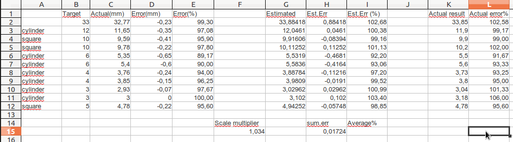
Well, regarding scaling;
(see attachment)
Column:
A = expected sizes of the test piece, and it's holes
B =measured the printed results
C =error in mm
E =error in %
F - I tweaked a multiplier so that estimate looked good. giving lowest possible sum of over & undershoot (H15)
G shows estimated sizes (column C * F15)
H estimated error in mm
I estimated error in % over expected size
printed with scale 1.034 for X&Y axis
K shows measured size
L is error % over expected size.
---------This proves to me that a simple linear scaling is not a proper way of handling this.
|
Re: Problems with high precision prints.. December 21, 2011 07:53PM |
Admin Registered: 17 years ago Posts: 7,879 |
I think the errors are too big to be due to shrinkage. Your scale factor is an order of magnitude more than the one I use for ABS and PLA shrinks less. Perhaps you have some backlash in your axes. That would subtract a constant from the linear dimensions.
Circles shrink more for the reasons I have blogged.
[www.hydraraptor.blogspot.com]
Circles shrink more for the reasons I have blogged.
[www.hydraraptor.blogspot.com]
|
Re: Problems with high precision prints.. December 22, 2011 02:47AM |
Registered: 12 years ago Posts: 102 |
Yes, I've excluded circles as a problem.
regarding backlash - I were not sure how to test it, but while the needle pointed at a ruler, I could "walk" back and forth 1mm and 10mm and it pointed at the same place (I checked it in order to know if the calibration needed to be done while moving in one direction, like from left->right or if there were some slack.) The geared pulleys are printed, and one of them, when rotated, one of them were a *little* skew, I trimmed it with an xacto knife. all the random tests like walking 1mm at a time, and printing the "0.5mm test square" suggests that it's ok - I can print two squares, and stack them perfectly on each other, top to to, then rotate one, and they are still a perfect fit.
It needs to be said, that the numbers I posted are "average" or "min-max" of the measured errors.
Could it be some "bad" PLA ? (it's a new reel) , no "puffs" or bubbles, - and It's mounted in a clear bag with a big, baked, silica gel pack and a paper moisture indicator. It's not pink at the 5% mark yet.
|
Re: Problems with high precision prints.. December 22, 2011 03:22AM |
Registered: 12 years ago Posts: 102 |
Btw: one issue I suspected, was that when an "hole" is made, it makes (extrudes) a square, then another one outside the square, then jams in a fill between those two. - I reduced the number of walls without success, printing a solid (100%fill) cube does not result in a blob
- so I assume that even the three lines outside - while appearing as one level, wider area after the third line is put inbetween, is not overfilled.
the only way I can verify that - is the stop the machine after drawing the inner and outer line, and stop it when 50% of the center lane is extruded ? - so I can measure if the width changes as the middle line is made ?
Os is there some setting that adjusts just that, density of solid areas ?
|
Re: Problems with high precision prints.. December 22, 2011 11:22AM |
Registered: 13 years ago Posts: 581 |
Through a ton of trial and error I've found you want a constant road width, which is slightly wider than the nozzle diameter, regardless of layer height.
Makes sense to calculate width/thickness based on the nozzle diameter and layer height, then.
I'm just assuming that is what they are doing, since I have not used the more recent versions of slic3r and sfact.
nophead Wrote:
-------------------------------------------------------
> I use custom firmware and software. Although my
> extruder is stepper based I simply turn it on at
> the speed calculated by the host at the start of a
> filament run and turn it off at the end (with
> reversal and fast forward of course). I don't
> synchronise it with the axes.
>
> I only use SF to calculate the tool path, nothing
> else, so when I slice a file the g-code is machine
> independent. As I only use the path information in
> it I can print it on different machines and with
> different plastic. I am curious why the nozzle
> size has appeared in SFACT and Slic3r as it
> doesn't appear in any of my calculations. What do
> they do with it?
www.Fablicator.com
|
Re: Problems with high precision prints.. December 22, 2011 12:35PM |
Admin Registered: 17 years ago Posts: 7,879 |
Yes the nozzle dictates the range of widths that will work, but both SFACT and Slic3r also specify thickness and width, so I can't see what the nozzle setting can do unless it warns you when the width is out of range, but that is plastic dependent.
The critical figure is actually the die swell diameter, not the nozzle aperture. That sets the maximum filament cross section.
[www.hydraraptor.blogspot.com]
The critical figure is actually the die swell diameter, not the nozzle aperture. That sets the maximum filament cross section.
[www.hydraraptor.blogspot.com]
|
Re: Problems with high precision prints.. December 23, 2011 11:32AM |
Registered: 12 years ago Posts: 102 |
I have 0.5mm nozzle, but measured extrusion width is 0.6, based on actual measuring of the 0.5mm test print width. - not extrusion width,
this question remains: "Or is there some setting that adjusts just that, density of solid areas ?"
Because- if I reduce the extrusion ratio, single wall test suffers as well, it's no longer 0.6 mm wide then.
this question remains: "Or is there some setting that adjusts just that, density of solid areas ?"
Because- if I reduce the extrusion ratio, single wall test suffers as well, it's no longer 0.6 mm wide then.
|
Re: Problems with high precision prints.. December 24, 2011 01:15PM |
Registered: 13 years ago Posts: 202 |
nophead Wrote:
-------------------------------------------------------
> Yes the nozzle dictates the range of widths that
> will work, but both SFACT and Slic3r also specify
> thickness and width, so I can't see what the
> nozzle setting can do unless it warns you when the
> width is out of range, but that is plastic
> dependent.
The nozzle size in SFACT is for calculating "native flow". As you can basically specify extrusion width and layer height freely, I need the nozzle diameter to find a sweet spot for the supports (is like single wall printing) and for extrusion of bridges... As the layer height during the print is given flow is adjusted to flow at the sweet spot.
Slic3r uses nozzle diameter to calculate extrusion width at the sweet spot when the layer height is entered. The additional extrusion width is an "advanced feature" that you can play with if you feel confident enough to mess up with the settings..
Manufacturer of low tolerance Filaments PLA, ABS, ASA, PETG, TPU, PA, PVA,
[www.miafilament.com]
[github.com]
|
Re: Problems with high precision prints.. December 25, 2011 06:42AM |
Registered: 13 years ago Posts: 228 |
nophead Wrote:
-------------------------------------------------------
> Yes the nozzle dictates the range of widths that
> will work, but both SFACT and Slic3r also specify
> thickness and width, so I can't see what the
> nozzle setting can do unless it warns you when the
> width is out of range, but that is plastic
> dependent.
>
> The critical figure is actually the die swell
> diameter, not the nozzle aperture. That sets the
> maximum filament cross section.
Hello, I'm the Slic3r author. Ahmet pointed me to this thread.
The nozzle diameter is used in Slic3r for several purposes:
* to calculate the extrusion width for bridges, since layer height is not enforced in open air and threads come out as cylinders having the same diameter as the nozzle;
* to choose a good physical model for the extruded threads, since the relationship between the (desired) extrusion width and the nozzle diameter changes the cross-sectional shape of the threads (rectangle with semicircles, rectangle with shrunk arcs, "tear" etc.)
* to compute an optimal extrusion width (resulting from matching the feed rate and the flow speed rate at the nozzle) so that the user doesn't even have to set a custom extrusion width
Die swell is handled in Slic3r by a generic "extrusion multiplier" option which changes the extruded volume proportionally, since the die swell is, AFAIK, just a matter of different density.
The design difference between SF and Sfact/Slic3r is that SF doesn't include any physical model. It exposes every option to the user: flow rate, spacing, overlapping, bridge settings etc. Sfact and Slic3r try to provide a physical model of the extrusion process, by using relations between these settings. For example, if your equations only consider the balance between incoming and extruded plastic volume, you could say that by increasing the flow rate you could reach any extrusion width, even a very large one. We know from experience that this is not true: with a given combination of factors (including nozzle diameter) you can only get a range of extrusion widths. This is because the physical behavior of extrusion is more complex than just a volume balance.
|
Re: Problems with high precision prints.. December 25, 2011 04:53PM |
Admin Registered: 17 years ago Posts: 7,879 |
No they don't they come out as a cylinder defined by the flow rate and the feed rate. The nozzle does not appear in the equation, it only sets the limits of what is possible but that is also plastic dependent.Quote
* to calculate the extrusion width for bridges, since layer height is not enforced in open air and threads come out as cylinders having the same diameter as the nozzle;
I use the maths here: [hydraraptor.blogspot.com] and nozzle diameter does not come into it.Quote
* to choose a good physical model for the extruded threads, since the relationship between the (desired) extrusion width and the nozzle diameter changes the cross-sectional shape of the threads (rectangle with semicircles, rectangle with shrunk arcs, "tear" etc.)
Quote
* to compute an optimal extrusion width (resulting from matching the feed rate and the flow speed rate at the nozzle) so that the user doesn't even have to set a custom extrusion width
Not sure what you mean by "optimal". A W/T of 1.5 is about the best for horizontal resolution and build speed, higher values are better for vertical resolution and overhangs. Again nothing to do with the nozzle diameter.
Quote
For example, if your equations only consider the balance between incoming and extruded plastic volume, you could say that by increasing the flow rate you could reach any extrusion width, even a very large one. We know from experience that this is not true: with a given combination of factors (including nozzle diameter) you can only get a range of extrusion widths. This is because the physical behavior of extrusion is more complex than just a volume balance.
All the maths can be done with volume balance. The nozzle diameter simply sets the minimum and maximum filament cross sections that you can extrude, but it is also plastic dependent, so the nozzle size alone is not enough information. The biggest cross section you can build with is the die swell size and that depends on the nozzle, the plastic, the temperature and the flow rate. The only practical way to find it is to extrude into mid air and measure it.
The smallest cross section is when the plastic is stretched so far it snaps. Again that depends on nozzle, plastic and temperature.
The way I view it is that for a given nozzle size and plastic there is a minimum and maximum usable filament cross section. Within those limits you can use any W/T from 1.5 upwards and any flow rate from 0 to the limit the extruder can deliver. T can be set to any value respecting these limits.
Edited 1 time(s). Last edit at 12/25/2011 05:58PM by nophead.
[www.hydraraptor.blogspot.com]
|
Re: Problems with high precision prints.. December 26, 2011 07:28AM |
Registered: 12 years ago Posts: 102 |
Sorry, only registered users may post in this forum.